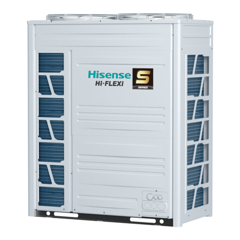
DC-InverterAir Conditioner Technical & Service Manual
Table of Contents
1. General ..................................................................................................................................................1
1.1 Features........................................................................................................................................1
1.2 Product lineup...............................................................................................................................5
1.3 Nomenclature ...............................................................................................................................5
1.4 Unit installation .............................................................................................................................6
1.5 Working range...............................................................................................................................6
1.6 Product appearance .....................................................................................................................7
2. Specifications.......................................................................................................................................14
2.1 Duct type.....................................................................................................................................14
2.2 Cassette type..............................................................................................................................18
2.3 Ceiling & Floor type ....................................................................................................................22
2.4 Console type...............................................................................................................................26
3. Outlines and dimensions......................................................................................................................28
3.1 Indoor units .................................................................................................................................28
3.2 Outdoor units ..............................................................................................................................35
4. Electrical data .....................................................................................................................................41
5. Capacities and selection data..............................................................................................................42
5.1 Capacity characteristic charts.....................................................................................................36
5.2 Piping length correction factor ....................................................................................................61
5.3 Correction factors according to defrosting operation..................................................................63
6. Sound pressure data ...........................................................................................................................64
7. Air flow distribution...............................................................................................................................75
7.1 Cassette type..............................................................................................................................75
7.2 Ceiling & Floor type ....................................................................................................................84
8. ESP (External static pressure) chart (Duct type).................................................................................98
9. Refrigerant cycle ................................................................................................................................107
10. Fresh air intake function...................................................................................................................113
11. Wiring diagram.................................................................................................................................115
11.1 Electrical wiring diagrams .......................................................................................................115
11.2 Control board picture ..............................................................................................................125
11.3 Common wiring.......................................................................................................................130
12. Field setting.....................................................................................................................................132
12.1 Indoor unit air flow DIP switch ................................................................................................132
12.2 Outdoor unit DIP switch ..........................................................................................................133
12.3 ESP setting .............................................................................................................................134
12.4 Indoor unit parameter revision ................................................................................................135
12.5 Running parameter query.......................................................................................................137
12.6 Instructions for the function setting of access control, fire protection .....................................140
13. Piping work and refrigerant charge ..................................................................................................142
13.1 MAX. length allowed ...............................................................................................................142
13.2 Oil trap ....................................................................................................................................142
13.3 Air tight test.............................................................................................................................143
13.4 Additional refrigerant charge...................................................................................................144
14. Control mode ...................................................................................................................................145
14.1 Indoor unit mode control ........................................................................................................145
14.2 Outdoor unit mode control ......................................................................................................148
15. Sensor parameter ............................................................................................................................149
16. Troubleshooting................................................................................................................................155
16.1 Trouble guide ..........................................................................................................................155
16.2 Fault codes .............................................................................................................................161
17. Checking components ....................................................................................................................170
17.1 Check refrigerant system........................................................................................................170
17.2 Check parts unit .....................................................................................................................172
18. Disassembly and assembly for compressor and motor ...................................................................177
19. Control logic description...................................................................................................................194
