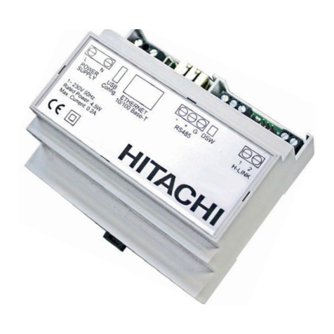
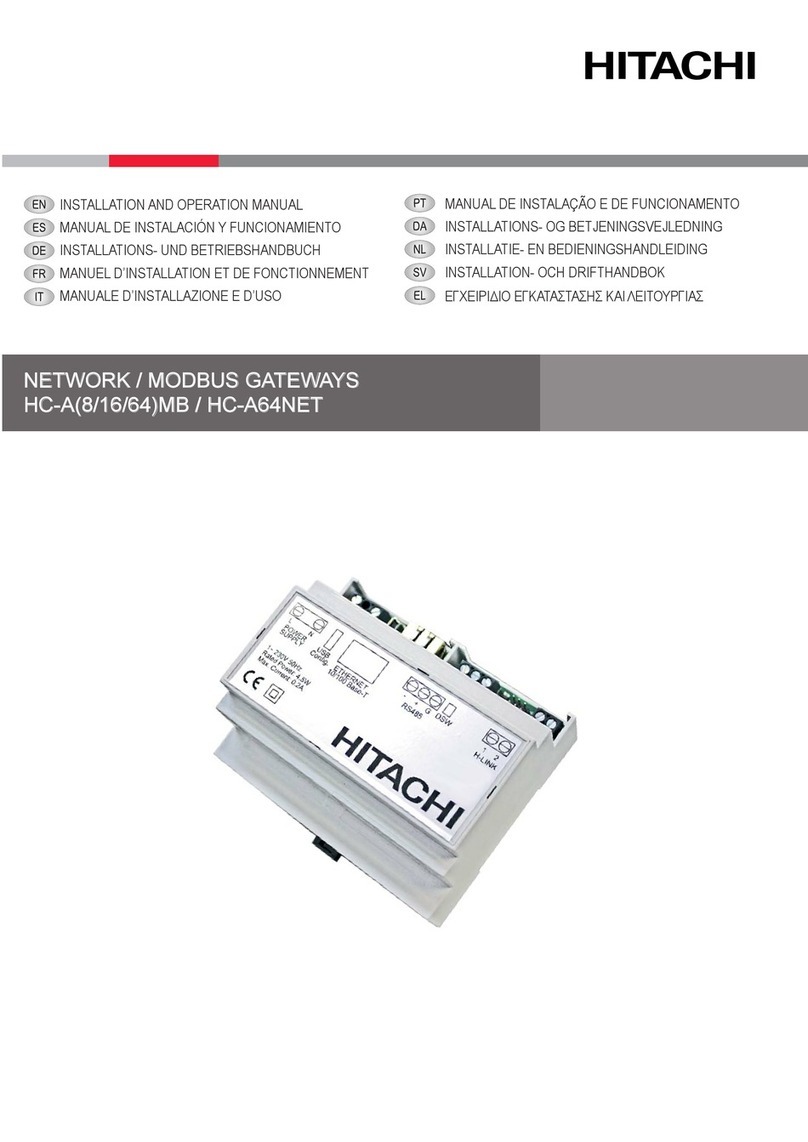
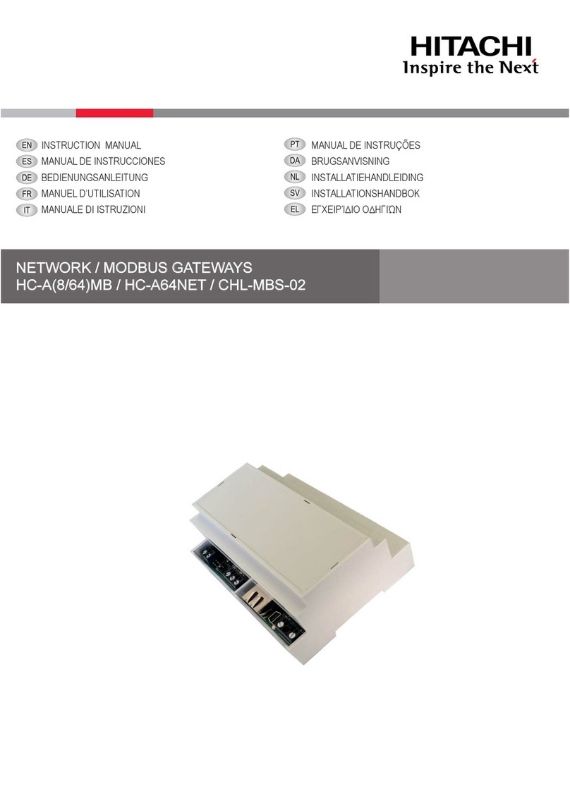
Hitachi HC-A8MB User manual

NETWORK / MODBUS GATEWAYS
HC-A(8/16/64)MB / HC-A64NET
INSTALLATION AND OPERATION MANUAL INSTALLATIONS- OG BETJENINGSVEJLEDNING I


English
Specifications in this manual are subject to change without notice in order that Hitachi may bring the latest innovations to
their customers.
Whilst every effort is made to ensure that all specifications are correct, printing errors are beyond Hitachi’s control;
Hitachi cannot be held responsible for these errors.
Dansk
Specifikationerne i denne vejledning kan ændres uden varsel, for at Hitachi kan bringe de nyeste innovationer ud til
kunderne.
På trods af alle anstrengelser for at sikre at alle specifikationerne er korrekte, har Hitachi ikke kontrol over trykfejl, og
Hitachi kan ikke holdes ansvarlig herfor.

!CAUTION
This product shall not be mixed with general house waste at the end of its life and it shall be retired according to the
appropriated local or national regulations in a environmentally correct way.
Due to the refrigerant, oil and other components contained in Air Conditioner, its dismantling must be done by a professio-
nal installer according to the applicable regulations. Contact to the corresponding authorities for more information.
!ADVARSEL!
At produktet ikke må smides ud sammen med almindeligt husholdningsaffald, men skal bortskaffes i overensstemmelse med de
gældende lokale eller nationale regler på en miljømæssig korrekt måde.
Da klimaanlægget indeholder kølemiddel, olie samt andre komponenter, skal afmontering foretages af en fagmand i overenss-
temmelse med de gældende bestemmelser.
Kontakt de pågældende myndigheder for at få yderligere oplysninger.

!
DANGER – Hazards or unsafe practices which COULD result in severe personal injuries or death.
FARE – Farer eller farlig brug, som KAN resultere i alvorlig personskade eller dødsfald.
!
CAUTION – Hazards or unsafe practices which COULD result in minor personal injury or product or property damage.
FORSIGTIG – Farer eller farlig brug, som KAN resultere i mindre skade på personer, produkt eller ejendom.
?
NOTE – The text following this symbol contains information or instructions that may be of use or that require a more thorough explanation.
BEMÆRK – Den tekst, der følger efter dette symbol, indeholder oplysninger eller anvisninger, der kan være til nytte, eller som kræver en
mere grundig forklaring.

1 PRODUCT GUIDE
1.1 CLASSIFICATION OF THE UNITS
Interface Controller Control
Dash separation
H-LINK II Compatible
Maxim Number of Controllable Units (8/16/64)
MB: Modbus gateway
NET: Gateway for CSNET Manager
HC - A X X
1.2 MODELS
DESCRIPTION
HC-A8MB
HC-A16MB
HC-A64MB
HC-A64NET
1.3 ACCESSORY LIST
DESCRIPTION
Net conguration kit
ENGLISH
PRODUCT GUIDE
PMML0351A rev.4 - 04/2020
1

2 NEW PRODUCT GENERAL DATA
2.3.1 Hardware specications
Item Specications
Power supply 1~ 230 V ±10% 50 Hz
Consumption 4.5W (maximum)
Outer dimensions Width: 106 mm, Depth: 90 mm, Height: 58 mm
Weight 165 g
Assembling conditions Indoors (installation inside an enclosure with restricted access by a tool)
Ambient temperature 0~60 ºC
Humidity 20~85% (Without condensation)
2.3.2 Communication
RS485
Item Specications
Type Modbus RTU for HC-A(8/16/64)MB
Not available for HC-A64NET
Connector Serial Port RS485 (3 screw terminals)
Communication line Shielded twisted pair cable, with third wire (for the common), with polarity.
Communication system Half-duplex, multipoint serial connection
Communication method Non parity or odd/even parity selection. Data length: 8 bits – 1 stop bit
Baud rate transmission 19200/9600 Baud
Length Max. 1200 m according EIA-485
Ethernet
Item Specications
Type Modbus TCP for HC-A(8/16/64)MB
TCP/IP communication for HC-A64NET
Connector Ethernet (RJ45)
Communication line Two twisted pair cable CAT5 or better (T-568A/T-568B)
Communication system Full-duplex
Length Max. 100 m according IEEE 802.3
H-LINK
Item Specications
Communication with HC-A(16/64)MB: SET FREE, UTOPIA, CENTRIFUGAL and HEATING systems
HC-A8MB and HC-A64NET: SET FREE, UTOPIA and CENTRIFUGAL systems
Communication line Twisted pair shielded cable, non-polarity
Communication system Half-duplex
Communication method Asynchronous
Speed of transmission 9600 Bauds
Length of wiring 1000 m maximum (total length of H-LINK I/O bus)
Maximum number of gateways 1 Gateway (HC-A(8/16/64)MB) / H-LINK SYSTEM
Maximum number of IU
HC-A64MB → up to 64 * Indoor Units
HC-A16MB → up to 16 * Indoor Units
HC-A8MB → up to 8 * Indoor Units
HC-A64NET → up to 64* Indoor Units
NEW PRODUCT GENERAL DATA
PMML0351A rev.4 - 04/2020
2
3 INSTALLATION
3.1 SAFETY SUMMARY
!DANGER
• Readcarefullythismanualbeforeperformingtheinstallationwork.
• Donotinstallthisdeviceinplacesaccessibletothegeneralpublic.Installitinelectricalenclosures,whichareonlyaccessiblebythe
usageofatoolandalsoprovideprotectiontoeventualelectromagneticdisturbances.
• Donotconnectpowersupplybeforethedeviceinstallationiscorrectlydone.Alwaysdisconnectpowersupplyfromthedevicebefore
anymaintenanceorservicingaction.
!CAUTION
• Thisappliancemustbeusedonlybyadultandcapablepeople,havingreceivedthetechnicalinformationorinstructionstohandleproperlyand
safelythisappliance.
• ThisisaClassAproduct.Inadomesticenvironmentthisproductmaycauseradiointerferencesinwhichcasetheusermayberequiredtotake
adequatemeasures.
• Childrenshouldbesupervisedtoensurethattheydonotplaywiththeappliance.
• Checktoensurethattheeldsuppliedelectricalcomponents(mainspowerswitches,circuitbreakers,wires,connectorsandwireterminals)have
beenproperlyselectedaccordingtotheelectricaldataindicatedonthisdocumentandtheycomplywithnationalandlocalcodes.Ifitisnecessary,
contactwithyourlocalauthorityinregardstostandards,rules,regulations,etc.
• DonotinstallNetwork/Modbusgatewaysinplaces:
- whereanyvapor,oilorotherdispersedliquidscouldaffectthedevice.
- whereaccumulation,generationorleaksofinammablegaseshasbeendetected.
- neartoanyheatsourcesorelectromagneticnoisesources.
- thattheyareneartothesea,insaline,acidoralkalinesurroundings.
3.2 FACTORY-SUPPLIED COMPONENTS
Gateway device Instruction manual USB Pen Drive Memory
1x 1x 1x
3.3 DIMENSIONAL DATA
Rail DIN 35 mm
ENGLISH
INSTALLATION
PMML0351A rev.4 - 04/2020
3

3.4 DESCRIPTION OF THE PARTS
(mm)
No. Description
External power supply
USB cable at conguration time only
RJ45 Ethernet
HC-A(8/16/64)MB: Modbus TCP
HC-A64NET : TCP/IP
RS485
Modbus RTU for HC-A(8/16/64)MB
Not available for HC-A64NET
H-LINK Communication bus with Hitachi
units
Operation led indicator
Rail DIN 35 mm for assembly inside the
electrical box
3.5 INSTALLATION SPACE
Keep free the grey area for the correct operation of the device.
(mm)
INSTALLATION
PMML0351A rev.4 - 04/2020
4

3.6 INSTALLATION PROCEDURE
!DANGER
• Donotinstallthisdeviceinplacesaccessibletothegeneralpub-
lic.Installitinenclosuresorotherplaceswhichareaccessible
onlybytheusageofatool.
• Do not connect power supply before the device installation is
correctlydone.Alwaysdisconnectpowersupplyfromthedevice
beforeanymaintenanceorservicingaction
!CAUTION
• Checktoensurethattheeldsuppliedelectricalcomponents(mains
powerswitches, circuit breakers,wires, connectorsandwire termi-
nals)havebeenproperlyselectedaccordingtotheelectricaldataindi-
catedonthisdocumentandtheycomplywithnationalandlocalcodes
• Anyunitthatisnotconnectedorisnotunderpowerwhenturningon
Network/Modbusgateways,willnotberecognizedandwillhaveto
beconguredlater.
-BeforepowersupplyandturningontheNetwork/Modbus
gateways,youmustensurethat:
¡1.Allcircuitstobeconnectedarecorrectlyapplied.
¡2.AllH-Linkconnectionshavebeensetup.
¡3.Modbusconnectionhasbeenproperlydone.
• Thesignals’cablesshouldbeasshortaspossible.Keepadistanceof
morethan150mmfromotherpowercables.Donotwirethemtogether
(althoughtheymayintersect).Iftheymustnecessarilybeinstalledto-
gether,takethefollowingmeasurestoavoidnoisedisturbances:
-Forcommunications,useshieldedwirewhichisearthedatone
side.
3.7 NETWORK CONFIGURATION
It is supplied a computer software tool, Net conguration Tool, inside the USB stick memory for an easy and friendly conguration.
3.7.1 Computer requirements.
It is required to use a personal computer with Microsoft Windows
7 or higher, a free USB port and Java.
3.7.2 Parameters under conguration:
-Parity:Odd/Even/Disabled
-Communicationspeed:9600/19200Bps
-Modbusaddress
-ModbusTCPIP
3.7.3 Conguration procedure
Conguration through USB port
This method is required when the device IP is unknown.
1 Connect the network device to a computer by a USB cable
(eld supplied or available with the Net Conguration Kit)
2 Select the communication port of the computer.
3 Press the button at screen
ENGLISH
INSTALLATION
PMML0351A rev.4 - 04/2020
5

Conguration through Ethernet port
1 Connect the Network device to a computer by a ethernet cable (eld supplied or available with either the Net Conguration Kit or
the CSNET MANAGER)
2 Input the following parameters:
• IP Address: 192.168.0.4
• Port: Modbus Gateway/ HC-A64NET
3 Press the button at screen
Conguration of device and communication
HC-A(8/16/64)MB HC-A64NET
“Device information”
Check that the network device is correctly displayed at the “Device information” table. Press refresh button if necessary.
INSTALLATION
PMML0351A rev.4 - 04/2020
6

“Network information”
When the network device is integrated to the LAN / Modbus net by Ethernet, congure the following parameters:
• IP Address: Allow to modify the IP of the Network device port (“192.168.0.4” by default).
• Mask: Ask to your IT technician for the proper value (“255.255.255.0” by default).
• Gateway: LAN gateway address (“192.168.0.1” by default).
“Serial Information”
When the network device is integrated to the Modbus net by serial port RS485, congure the following parameters:
• RS485: 9600 / 19200 Bps (“19200” Bps by default)
• RS485: None / Odd / Even parity (“Even” by default)
• Modbus Id: 1~128 (“1” by default)
• Polarization: Communication polarization (“Disabled” by default)
?NOTE
ThispartisnotavailablefortheHC-A64NET
“Units Id Conguration”
• Automatic address can be done by pushing
• Manual address conguration can be done by the assignation of each Id to a specic H-LINK addresss
-Outdoorunitaddress(Ou)andIndoorunitaddress(Iu)
• Conrm the conguration by pressing
• Refresh button shall be pressed when modiy the units conneced to the net
?NOTE
ThispartisnotavailablefortheHC-A64NET
ENGLISH
INSTALLATION
PMML0351A rev.4 - 04/2020
7

4 ELECTRICAL WIRING
Name Connection Cable specication
X1 Power supply (1) Use 0.75 mm2 wires which are not lighter than the polychloroprene sheathed
exible cord (code designation 60245 IEC 57)
X3 Ethernet (1)
Category 5 or higher LAN cables
PC connection: Use a crossed cable (1 cable set available in Net conguration
Kit) for direct connection.
LAN connection: Use a direct cable (eld-supplied) for connection to a commercial
distributor (Hub).
X4 H-LINK (1) Twisted pair shielded cable 0.75 mm².
Shield must be grounded in one side only.
X5 RS485 (1) 3 cores cable harness 0.75 mm² grounded in one side only. Use different colour
for each cable.
X6 USB (1) USB Mini-B plug cable (1 cable set available in Net conguration Kit)
?NOTE
(1)Thesecablesmustbeeldsupplied.
4.1 DSW CONFIGURATION
Name Function Factory
setting Description
SW1 Conguration
SW1-1: Modbus end
resistance (*).
SW1-2: Not used (keep
always “ON”)
?NOTE
(*)NoapplicabletoHC-A64NET.
5 OPERATION
5.1 COMPATIBILITY
These devices are not compatible with any of the following Hitachi controllers:
-Centralisedremotecontrols
-Buildingairconditioningcontrols(*)
-OtherHitachiBMSGateways(LONWORKS,BACNET,KNX,FIDELIO)
-OtherHitachiMODBUSGateways
-Otherunitsofthesamemodel
?NOTE
(*)HC-A64NETiscompatiblewithCSNETManager.
ELECTRICAL WIRING
PMML0351A rev.4 - 04/2020
8

5.2 INDOOR UNITS
5.2.1 Available data for HC-A(8/16/64)MB
Offset (1) Description Values Read/Write
0 Exist 0: No exist
1: Exist Read
1 System address 0~63 Read
2 Unit address
3 On/Off setting order 0: Stop
1: Run Read/Write
4 Mode setting order
0: Cool
1: Dry
2: Fan
3: Heat
4: Auto
Read/Write
5 Fan setting order
0: Low
1: Medium
2: High
3: High2
4: Auto
Read/Write
6 Setting temperature ºC (set according to the unit working range) Read/Write
7 Louver setting 0 ~ 7 (7 is Auto) Read/Write
8 Central setting (3)
Bit 0: On/Off (always can be stopped)
Bit 1: Mode
Bit 2: Setting Temp
Bit 3: Fan
Bit 4: Louver
Read/Write
9 On/Off status 0: Off
1: On Read
10 Mode status
0: Cool
1: Dry
2: Fan
3: Heat
4: Auto
Read
11 Fan status
0: Low
1: Medium
2: High
3: High2
4: Auto
Read
12 Setting temperature status ºC (set according to the unit working range) Read
13 Louver status 0 ~ 7 (7 is Auto) Read
14 (Not used) (Not used) (Not used)
15 Inlet temperature reading (2) -63ºC ~ 63ºC Read
16 Outlet temperature reading (2) -63ºC ~ 63ºC Read
17 Gas pipe temperature reading (2) -63ºC ~ 63ºC Read
18 Liquid pipe temperature reading (2) -63ºC ~ 63ºC Read
19 Alarm code Alarm unit from 7-segment Read
20 Compressor stop cause (Read unit service manual) Read
21 Indoor unit expansion valve opening 0~100 Read
ENGLISH
OPERATION
PMML0351A rev.4 - 04/2020
9

Offset (1) Description Values Read/Write
22 Unit operation condition
0: OFF
1: Thermo OFF
2: Thermo ON
3: Alarm
Read
23 (Not used) (Not used) (Not used)
24 Ambient temperature (2) -63ºC ~ 63ºC Read
25 Remote control switch temperature
(only when available in the unit) (2) -63ºC ~ 63ºC Read
26 Remote control switch conguration b0: 0 Master/1Slave
b1: 0 wih RCS/1 Without RCS Read/Write
27 Remote control switch group 0: No group
1~255 Read/Write
28~30 (Not used) (Not used) (Not used)
31 Remote sensor temperature (2) -63ºC ~ 63ºC Read
?NOTE
• (1)Registeraddressiscalculatedas:“N+(Address*32)+Offset”where:
• N:Datatablepositionis2000,position20000isalsoavailabletomaintaincompatibilitywitholdModbusgateway.
• Address:Indoorunitaddressasconguredbycongurationsoftware.
• (2)Thesenumbersrefertosigned16-bitvalueusing2-complementformatfornegativevalues
• (3)Bit0(ON/OFF)andBit4(Louver)selectableonlywhenallcentralsareactived.
• InordertofulllocksettingfromRCS(CentralshowninRCS)setthisregisterto31.
OPERATION
PMML0351A rev.4 - 04/2020
10

5.2.2 Available Data for HC-A(16/64)MB
Offset Description Values Read/Write Availability
VRF RAC ATW
0 Exist 0: No exist Read O O
1: Exist
1 System address H-LINK 1: 0~15 Read O O
2 Unit address H-LINK 2: 0~63 O O
3 Type 0: Indoor Unit Read O O
4 On/Off setting order 0: Stop Read/Write O O
1: Run
5 Mode setting order
0: Cool
Read/Write O O
1: Dry
2: Fan
3: Heat
4: Auto
6 Fan setting order
0: Low
Read/Write O O
1: Medium
2: High
3: High2
4: Auto
7 Setting temperature ºC (set according to the
unit working range) Read/Write O O
8Temperature setting with 0.5°C inter-
vals
ºC x 10 (19.5ºC read
as 195) Read/Write O
9Heating temperature setting for AUTO
Cool/Heat ºC Read/Write O
10 Heating Temperature setting for AUTO
Cool/heat with 0.5°C intervals
ºC x 10 (19.5ºC read
as 195) Read/Write O
11 Cooling Temperature setting for AUTO
Cool/heat ºC Read/Write O
12 Cooling Temperature setting for AUTO
Cool/heat with 0.5°C intervals
ºC x 10 (19.5ºC read
as 195) Read/Write O
13 Louver setting 0 ~ 7 (7 is Auto) Read/Write O
14 Central setting (2)
Bit 0: On/Off (always
can be stopped)
Read/Write O O
Bit 1: Mode
Bit 2: Setting Temp
Bit 3: Fan
Bit4: Louver
15 On/Off status 0: Off Read O O
1: On
16 Mode status
0: Cool
Read O O
1: Dry
2: Fan
3: Heat
4: Auto
17 Fan status
0: Low
Read O O
1: Medium
2: High
3: High2
4: Auto
18 Setting temperature status ºC (set according to the
unit working range) Read O O
ENGLISH
OPERATION
PMML0351A rev.4 - 04/2020
11

Offset Description Values Read/Write Availability
VRF RAC ATW
19 Temperature setting with 0.5°C inter-
vals status
ºC x10 (19.5ºC read as
195) Read O
20 Heating temperature setting for AUTO
Cool/Heat status ºC Read O
21 Heating Temperature setting for AUTO
Cool/heat with 0.5°C intervals status
ºC x 10 (19.5ºC read
as 195) Read O
22 Cooling Temperature setting for AUTO
Cool/heat status ºC Read O
23 Cooling Temperature setting for AUTO
Cool/heat with 0.5°C intervals status
ºC x 10 (19.5ºC read
as 195) Read O
24 Louver status 0 ~ 7 (7 is Auto) Read O
25 Air inlet temperature reading -63ºC ~ 63ºC Read O
26 Air outlet temperature reading -63ºC ~ 63ºC Read O
27 Gas pipe temperature reading -63ºC ~ 63ºC Read O
28 Liquid pipe temperature reading -63ºC ~ 63ºC Read O
29 Alarm code Alarm unit from 7-seg-
ment Read O O(1)
30 Compressor stop cause (Read unit service ma-
nual) Read O
31 Indoor unit expansion valve opening 0~100 Read O
32 Unit operation condition
0: OFF
Read O O
1: Thermo OFF
2: Thermo ON
3: Alarm
33 Remote temperature sensor (THM4)
value -63ºC ~ 63ºC Read O
34 Remote control switch temperature
(only when available in the unit) -63ºC ~ 63ºC Read O O
35 Remote control switch conguration
b0: 0 Master/1Slave
Read/Write O
b1: 0 wih RCS/1 Without
RCS
36 Remote control switch group 0: No group Read/Write O
1~255
37 CN3 Conguration status
b0: Input 1 open/close
Read O
b1: Input 2 open/close
b2: Enabled/Disabled
(Indicates if the unit has
CN3 enabled with any
function)
38~49 Reserved
50 Control Unit Run/Stop 0: Stop Read/Write O
1: Run
51 Control Unit Mode 0: Cool Read/Write O
1: Heat
52 Control Circuit 1 Run/Stop 0: Stop Read/Write O
1: Run
53 Control Heat. OTC Zone 1
0: No
Read/Write O
1: Points
2: Gradient
3: Fix
54 Control Cool. OTC 1
0: No
Read/Write O1: Points
2: Fix
OPERATION
PMML0351A rev.4 - 04/2020
12

Offset Description Values Read/Write Availability
VRF RAC ATW
55 Control Circuit 1: Water heating Fix
Setting Temp 0~80 Read/Write O
56 Control Circuit 1: Water cooling Fix
Setting Temp 0~80 Read/Write O
57 Control Circuit 1: Eco mode 0: ECO Read/Write O
1: Comfort
58 Control Circuit 1: Heat ECO Offset
Temperature 1~10 Read/Write O
59 Control Circuit 1: Cool ECO Offset
Temperature 1~10 Read/Write O
60 Control Circuit 1: External MBS/KNX
Thermostat Available
0: Not Available Read/Write O
1: Available
61 Control Zone 1: Thermostat Setting 0~65535 Read/Write O
62 Control Zone 1: Room Ambient Tem-
perature -32667~32667 Read/Write O
63 Control Circuit 2 Run/Stop 0: Stop Read/Write O
1: Run
64 Control Heat. OTC Zone 2
0: No
Read/Write O
1: Points
2: Gradient
3: Fix
65 Control Cool. OTC Zone 2
0: No
Read/Write O1: Points
2: Fix
66 Control Circuit 2: Water heating Fix
Setting Temp 0~80 Read/Write O
67 Control Circuit 2: Water cooling Fix
Setting Temp 0~80 Read/Write O
68 Control Circuit 2: Eco mode 0: ECO Read/Write O
1: Comfort
69 Control Circuit 2: Heat ECO Offset
Temperature 1~10 Read/Write O
70 Control Circuit 2: Cool ECO Offset
Temperature 1~10 Read/Write O
71 Control Circuit 2: External MBS/KNX
Thermostat Available
0: Not Available Read/Write O
1: Available
72 Control Zone 2: Thermostat Setting 0~65535 Read/Write O
73 Control Zone 2: Room Ambient Tem-
perature -32667~32667 Read/Write O
74 Control DHWT Run/Stop 0: Stop Read/Write O
1: Run
75 Control DHWT Setting Temperature 0~80 Read/Write O
76 Control DHW Boost 0: No request Read/Write O
1: Request
77 Reserved
78 Control DHW Demand Mode 0: Standard Read/Write O
1: High demand
79 Control Swiming Pool Run/Stop 0: Stop Read/Write O
1: Run
80 Control Swiming Pool Setting Tempe-
rature 0~80 Read/Write O
81 Control AntiLegionella Run/Stop 0: Stop Read/Write O
1: Run
ENGLISH
OPERATION
PMML0351A rev.4 - 04/2020
13

Offset Description Values Read/Write Availability
VRF RAC ATW
82 Control AntiLegionella Setting Tem-
perature 0~80 Read/Write O
83 Control Block menu
0: No
Read/Write O
1: Block (user cannot
access the menu)
84 Control Yutaki Forced OFF 0: Normal Operation Read/Write O
1: Forced OFF
85 Space Heating Heater Forced OFF 0: Normal Operation Read/Write O
1: Heater Forced OFF
86 Control Communication Alarm bit 0: No Read/Write O
1: Alarm
87~99 Reserved
100 Status Unit Run/Stop 0: Stop Read O
1: Run
101 Status Mode B0: 0: Cool / 1: Heat Read O
B1: 0: Normal / 1: Auto
102 Status Circuit 1 Run/Stop 0: Stop Read O
1: Run
103 Status Heat. OTC 1
0: No
Read O
1: Points
2: Gradient
3: Fix
104 Status Cool. OTC 1
0: No
Read O1: Points
2: Fix
105 Status Circuit 1: Water heating Fix
Setting Temp 0~80 Read O
106 Status Circuit 1: Water cooling Fix
Setting Temp 0~80 Read O
107 Status Circuit 1: Eco mode 0: ECO Read O
1: Comfort
108 Status Circuit 1: Heat ECO Offset
Temperature 1~10 Read O
109 Status Circuit 1: Cool ECO Offset
Temperature 1~10 Read O
110 Status Circuit 1: Thermostat Setting
Temperature 50~350 (5,0~35,0) Read O
111 Status Circuit 1: Thermostat Room
Temperature 0~1000 (0,0~100,0) Read O
112 Status Circuit 1: Wireless Setting
Temperature 50~350 (5,0~35,0) Read O
113 Status Circuit 1: Wireless Room Tem-
perature 0~1000 (0,0~100,0) Read O
114 Status Circuit 2 Run/Stop 0: Stop Read O
1: Run
115 Status Heating OTC 2
0: No
Read O
1: Points
2: Gradient
3: Fix
116 Status Cooling OTC 2
0: No
Read O1: Points
2: Fix
OPERATION
PMML0351A rev.4 - 04/2020
14
Other manuals for HC-A8MB
2
This manual suits for next models
3
Table of contents
Languages:
Other Hitachi Gateway manuals

Hitachi
Hitachi CHL-MBS-02 User manual

Hitachi
Hitachi ATW-IOT-01 User manual

Hitachi
Hitachi ATW-MBS-02 User manual

Hitachi
Hitachi HC-A8MB User manual

Hitachi
Hitachi airCloud HC-IOTGW Instruction Manual

Hitachi
Hitachi CHL-BAC-01 User manual

Hitachi
Hitachi HC-A8MB User manual

Hitachi
Hitachi ATW-MBS-02 User manual

Hitachi
Hitachi ATW-TAG-01 User manual

Hitachi
Hitachi HC-A MB Series User manual