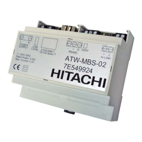
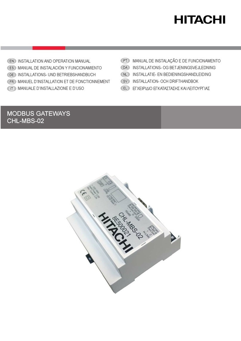
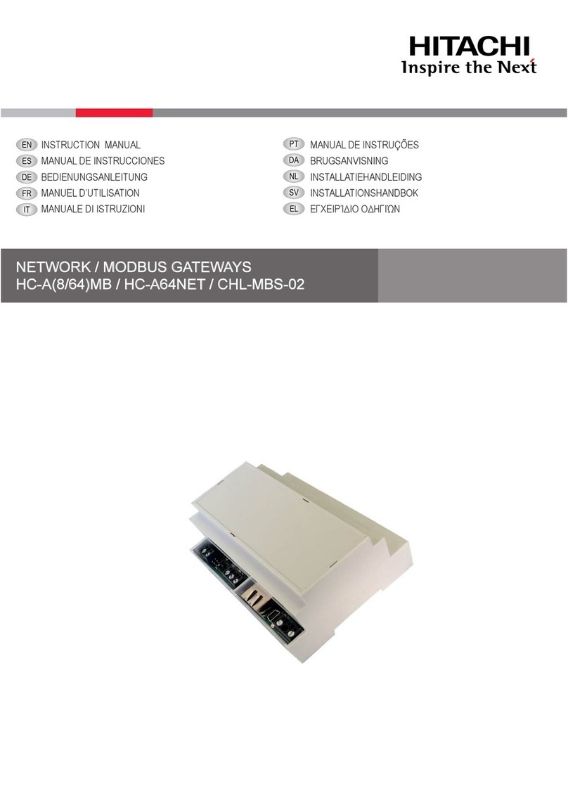
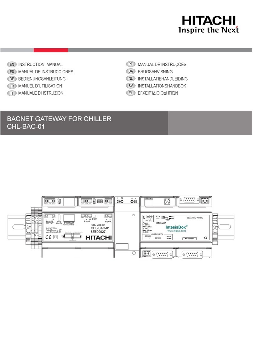
Hitachi HC-A8MB User manual

NETWORK / MODBUS GATEWAYS
HC-A(8/16/64)MB / HC-A64NET
INSTALLATION AND OPERATION MANUAL
MANUAL DE INSTALACIÓN Y FUNCIONAMIENTO
INSTALLATIONS- UND BETRIEBSHANDBUCH
MANUEL D’INSTALLATION ET DE FONCTIONNEMENT
MANUALE D’INSTALLAZIONE E D’USO
MANUAL DE INSTALAÇÃO E DE FUNCIONAMENTO
INSTALLATIONS- OG BETJENINGSVEJLEDNING
INSTALLATIE- EN BEDIENINGSHANDLEIDING
INSTALLATION- OCH DRIFTHANDBOK
ΕΓΧΕΙΡΙΔΙΟ ΕΓΚΑΤΑΣΤΑΣΗΣ ΚΑΙ ΛΕΙΤΟΥΡΓΙΑΣ


English
Specications in this manual are subject to change without notice in order that Hitachi may bring the latest innovations to
their customers.
Whilst every effort is made to ensure that all specications are correct, printing errors are beyond Hitachi’s control;
Hitachi cannot be held responsible for these errors.
Español
Las especicaciones de este manual están sujetas a cambios sin previo aviso a n de que Hitachi pueda ofrecer las
últimas innovaciones a sus clientes.
A pesar de que se hacen todos los esfuerzos posibles para asegurarse de que las especicaciones sean correctas, los
errores de impresión están fuera del control de Hitachi, a quien no se hará responsable de ellos.
Deutsch
Bei den technischen Angaben in diesem Handbuch sind Änderungen vorbehalten, damit Hitachi seinen Kunden die
jeweils neuesten Innovationen präsentieren kann.
Sämtliche Anstrengungen wurden unternommen, um sicherzustellen, dass alle technischen Informationen ohne Fehler
veröffentlicht worden sind. Für Druckfehler kann Hitachi jedoch keine Verantwortung übernehmen, da sie außerhalb ihrer
Kontrolle liegen.
Français
Les caractéristiques publiées dans ce manuel peuvent être modiées sans préavis, Hitachi souhaitant pouvoir toujours
offrir à ses clients les dernières innovations.
Bien que tous les efforts sont faits pour assurer l’exactitude des caractéristiques, les erreurs d’impression sont hors du
contrôle de Hitachi qui ne pourrait en être tenu responsable.
Italiano
Le speciche di questo manuale sono soggette a modica senza preavviso afnché Hitachi possa offrire ai propri clienti
le ultime novità.
Sebbene sia stata posta la massima cura nel garantire la correttezza dei dati, Hitachi non è responsabile per eventuali
errori di stampa che esulano dal proprio controllo.
Português
As especicações apresentadas neste manual estão sujeitas a alterações sem aviso prévio, de modo a que a Hitachi
possa oferecer aos seus clientes, da forma mais expedita possível, as inovações mais recentes.
Apesar de serem feitos todos os esforços para assegurar que todas as especicações apresentadas são correctas,
quaisquer erros de impressão estão fora do controlo da Hitachi, que não pode ser responsabilizada por estes erros
eventuais.
Dansk
Specikationerne i denne vejledning kan ændres uden varsel, for at Hitachi kan bringe de nyeste innovationer ud til
kunderne.
På trods af alle anstrengelser for at sikre at alle specikationerne er korrekte, har Hitachi ikke kontrol over trykfejl, og
Hitachi kan ikke holdes ansvarlig herfor.
Nederlands
De specicaties in deze handleiding kunnen worden gewijzigd zonder verdere kennisgeving zodat Hitachi zijn klanten
kan voorzien van de nieuwste innovaties.
Iedere poging wordt ondernomen om te zorgen dat alle specicaties juist zijn. Voorkomende drukfouten kunnen echter
niet door Hitachi worden gecontroleerd, waardoor Hitachi niet aansprakelijk kan worden gesteld voor deze fouten.
Svenska
Specikationerna i den här handboken kan ändras utan föregående meddelande för att Hitachi ska kunna leverera de
senaste innovationerna till kunderna.
Vi på Hitachi gör allt vi kan för att se till att alla specikationer stämmer, men vi har ingen kontroll över tryckfel och kan
därför inte hållas ansvariga för den typen av fel.
Eλλhnika
Οι προδιαγραφές του εγχειριδίου μπορούν να αλλάξουν χωρίς προειδοποίηση, προκειμένου η Hitachi να παρέχει τις
τελευταίες καινοτομίες στους πελάτες της.
Αν και έχει γίνει κάθε προσπάθεια προκειμένου να εξασφαλιστεί ότι οι προδιαγραφές είναι σωστές, η Hitachi δεν μπορεί
να ελέγξει τα τυπογραφικά λάθη και, ως εκ τούτου, δεν φέρει καμία ευθύνη για αυτά τα λάθη.

!CAUTION
This product shall not be mixed with general house waste at the end of its life and it shall be retired according to the
appropriated local or national regulations in a environmentally correct way.
Due to the refrigerant, oil and other components contained in Air Conditioner, its dismantling must be done by a professio-
nal installer according to the applicable regulations. Contact to the corresponding authorities for more information.
!PRECAUCIÓN
Éste producto no se debe eliminar con la basura doméstica al nal de su vida útil y se debe desechar de manera respetuosa con el
medio ambiente de acuerdo con los reglamentos locales o nacionales aplicables.
Debido al refrigerante, el aceite y otros componentes contenidos en el sistema de aire acondicionado, su desmontaje debe realizarlo un
instalador profesional de acuerdo con la normativa aplicable. Para obtener más información, póngase en contacto con las autoridades
competentes.
!VORSICHT
Dass Ihr Produkt am Ende seiner Betriebsdauer nicht in den allgemeinen Hausmüll geworfen werden darf, sondern entsprechend den
geltenden örtlichen und nationalen Bestimmungen auf umweltfreundliche Weise entsorgt werden muss.
Aufgrund des Kältemittels, des Öls und anderer in der Klimaanlage enthaltener Komponenten muss die Demontage von einem
Fachmann entsprechend den geltenden Vorschriften durchgeführt werden. Für weitere Informationen setzen Sie sich bitte mit den
entsprechenden Behörden in Verbindung.
!ADVERTISSEMENT
Ne doit pas être mélangé aux ordures ménagères ordinaires à la n de sa vie utile et qu’il doit être éliminé conformément à la réglemen-
tation locale ou nationale, dans le plus strict respect de l’environnement.
En raison du frigorigène, de l’huile et des autres composants que le climatiseur contient, son démontage doit être réalisé par un installa-
teur professionnel conformément aux réglementations en vigueur.
!AVVERTENZE
Indicazioni per il corretto smaltimento del prodotto ai sensi della Direttiva Europea 2011/65/EU e D.Lgs 4 marzo 2014 n.27.
Il simbolo del cassonetto barrato riportato sull’ apparecchiatura indica che il prodotto alla ne della propria vita utile deve essere raccolto
separatamente dagli altri riuti.
L’utente dovrà, pertanto, conferire l’apparecchiatura giunta a ne vita agli idonei centri di raccolta differenziata dei riuti elettronici ed
elettrotecnici, oppure riconsegnarla al rivenditore al momento dell’ acquisto di una nuova apparecchiatura di tipo equivalente.
L’adeguata raccolta differenziata delle apparecchiature dismesse, per il loro avvio al riciclaggio, al trattamento ed allo smaltimento
ambientalmente compatibile, contribuisce ad evitare possibili effetti negativi sull’ ambiente e sulla salute e favorisce il riciclo dei materiali
di cui è composta l’ apparecchiatura. Non tentate di smontare il sistema o l’unità da soli poichè ciò potrebbe causare effetti dannosi sulla
vostra salute o sull’ ambiente. Vogliate contattare l’ installatore, il rivenditore, o le autorità locali per ulteriori informazioni.
Lo smaltimento abusivo del prodotto da parte dell’utente può comportare l’applicazione delle sanzioni amministrative di cui all’articolo 50
e seguenti del D.Lgs. n. 22/1997.
!CUIDADO
O seu produto não deve ser misturado com os desperdícios domésticos de carácter geral no nal da sua duração e que deve ser elimi-
nado de acordo com os regulamentos locais ou nacionais adequados de uma forma correcta para o meio ambiente.
Devido ao refrigerante, ao óleo e a outros componentes contidos no Ar condicionado, a desmontagem deve ser realizada por um insta-
lador prossional de acordo com os regulamentos aplicáveis. Contacte as autoridades correspondentes para obter mais informações.
!ADVASEL!
At produktet ikke må smides ud sammen med almindeligt husholdningsaffald, men skal bortskaffes i overensstemmelse med de
gældende lokale eller nationale regler på en miljømæssig korrekt måde.
Da klimaanlægget indeholder kølemiddel, olie samt andre komponenter, skal afmontering foretages af en fagmand i overenss-
temmelse med de gældende bestemmelser.
Kontakt de pågældende myndigheder for at få yderligere oplysninger.
!VOORZICHTIG
Dit houdt in dat uw product niet wordt gemengd met gewoon huisvuil wanneer u het weg doet en dat het wordt gescheiden op een
milieuvriendelijke manier volgens de geldige plaatselijke en landelijke reguleringen.
Vanwege het koelmiddel, de olie en andere onderdelen in de airconditioner moet het apparaat volgens de geldige regulering door een
professionele installateur uit elkaar gehaald worden. Neem contact op met de betreffende overheidsdienst voor meer informatie.
!FÖRSIKTIGHET
Det innebär att produkten inte ska slängas tillsammans med vanligt hushållsavfall utan kasseras på ett miljövänligt sätt i enlighet med
gällande lokal eller nationell lagstiftning.
Luftkonditioneringsaggregatet innehåller kylmedium, olja och andra komponenter, vilket gör att det måste demonteras av en fackman i
enlighet med tillämpliga regelverk.
Ta kontakt med ansvarig myndighet om du vill ha mer information.
!ΠΡΟΣΟΧΗ
Σημαίνει ότι το προϊόν δεν θα πρέπει να αναμιχθεί με τα διάφορα οικιακά απορρίμματα στο τέλος του κύκλου ζωής του και θα πρέπει να
αποσυρθεί σύμφωνα με τους κατάλληλους τοπικούς ή εθνικούς κανονισμούς και με τρόπο φιλικό προς το περιβάλλον.
Λόγω του ψυκτικού, του λαδιού και άλλων στοιχείων που περιέχονται στο κλιματιστικό, η αποσυναρμολόγησή του πρέπει να γίνει από
επαγγελματία τεχνικό και σύμφωνα με τους ισχύοντες κανονισμούς.
Για περισσότερες λεπτομέρειες, επικοινωνήστε με τις αντίστοιχες αρχές.
!
DANGER – Hazards or unsafe practices which COULD result in severe personal injuries or death.
PELIGRO – Riesgos o prácticas poco seguras que PODRÍAN producir lesiones personales e incluso la muerte.
GEFAHR – Gefährliche oder unsichere Anwendung, die zu schweren Körperverletzungen oder zum Tod führen kann.
DANGER – Utilisation dangereuse ou sans garantie de sécurité qui PEUT provoquer de sévères blessures personnelles ou la mort.
PERICOLO – Pericoli o azioni pericolose che POTREBBERO avere come esito lesioni siche gravi o il decesso.
PERIGO – Riesgos o prácticas poco seguras que PUEDEN producir lesiones personales e incluso la muerte
FARE – Farer eller farlig brug, som KAN resultere i alvorlig personskade eller dødsfald.
GEVAAR – Gevaren of onveilige praktijken die ernstig persoonlijk letsel of de dood tot gevolg KUNNEN hebben.
FARA – Risker eller osäkra tillvägagångssätt som KAN leda till svåra personskador eller dödsfall.
KINAYNO – Κίνδυνοι ή επικίνδυνες πρακτικές, οι οποίες ΜΠΟΡΕΙ να έχουν ως αποτέλεσµα σοβαρές σωµατικές βλάβες ή θάνατο.
!
CAUTION – Hazards or unsafe practices which COULD result in minor personal injury or product or property damage.
PRECAUCIÓN – Riesgos o prácticas poco seguras que PODRÍAN provocar lesiones personales de menor importancia o daños en el
producto u otros bienes.
VORSICHT – Gefährliche oder unsichere Anwendung, die geringfügigen Personen-, Produkt- oder Sachschaden verursachen kann.
ATTENTION – Utilisation dangereuse ou sans garantie de sécurité qui PEUT provoquer des blessures mineures ou des dommages au
produit ou aux biens.
AVVERTENZA – Pericoli o azioni pericolose che POTREBBERO avere come esito lesioni siche minori o danni al prodotto o ad altri beni.
CUIDADO – Perigos e procedimentos perigosos que PODERÃO PROVOCAR danos pessoais ligeiros ou danos em produtos e bens.
FORSIGTIG – Farer eller farlig brug, som KAN resultere i mindre skade på personer, produkt eller ejendom.
LET OP – Gevaren of onveilige praktijken die licht persoonlijk letsel of beschadiging van het product of eigendommen tot gevolg KUN-
NEN hebben.
VARNING – Risker eller farliga tillvägagångssätt som KAN leda till mindre personskador eller skador på produkten eller på egendom.
ΠΡΟΣΟΧΗ – Κίνδυνοι ή επικίνδυνες πρακτικές, οι οποίες ΜΠΟΡΕΙ να έχουν ως αποτέλεσµα την πρόκληση ελαφρών σωµατικών βλαβών
ή καταστροφή περιουσίας.
?
NOTE – The text following this symbol contains information or instructions that may be of use or that require a more thorough explanation.
NOTA – El texto que sigue a este símbolo contiene información o instrucciones que pueden ser de utilidad o requeridas para ampliar una
explicación.
HINWEIS – Der diesem Symbol folgende Text enthält konkrete Informationen und Anleitungen, die nützlich sein können oder eine tiefer-
gehende Erklärung benötigen.
REMARQUE – Les textes précédés de ce symbole contiennent des informations ou des indications qui peuvent être utiles, ou qui méritent
une explication plus étendue.
NOTA – I testi preceduti da questo simbolo contengono informazioni o indicazioni che possono risultare utili o che meritano una spiegazi-
one più estesa.
NOTA – Os textos precedidos deste símbolo contêm informações ou indicações que podem ser úteis, ou que merecem uma explicação
mais detalhada.
BEMÆRK – Den tekst, der følger efter dette symbol, indeholder oplysninger eller anvisninger, der kan være til nytte, eller som kræver en
mere grundig forklaring.
OPMERKING – De teksten waar dit symbool voorstaat bevatten nuttige informatie en aanwijzingen, of informatie en aanwijzingen meer
uitleg behoeven.
OBS! – Texten efter denna symbol innehåller information och anvisningar som kan vara användbara eller som kräver en noggrannare
förklaring.
ΣΗΜΕΙΩΣΗ – Το κείμενο που ακολουθεί αυτό το σύμβολο περιέχει πληροφορίες ή οδηγίες που μπορεί να φανούν χρήσιμες ή που
απαιτούν μια πιο ενδελεχή εξήγηση.

EN English Original version
ES Español Versión traducida
DE Deutsch Übersetzte Version
FR Français Version traduite
IT Italiano Versione tradotta
PT Português Versão traduzidal
DA Dansk Oversat version
NL Nederlands Vertaalde versie
SV Svenska Översatt version
EL ΕΛΛΗΝιΚΑ Μεταφρασμένη έκδοση
INDEX
1 PRODUCT GUIDE
2 NEW PRODUCT GENERAL DATA
3 INSTALLATION
4 ELECTRICAL WIRING
5 OPERATION
6 NET CONFIGURATION KIT
ÍNDICE
1 GUÍA DEL PRODUCTO
2 DATOS GENERALES DEL NUEVO PRODUCTO
3 INSTALACIÓN
4 CABLEADO ELÉCTRICO
5 FUNCIONAMIENTO
6 KIT DE CONFIGURACIÓN DE LA RED
INHALT
1 PRODUKTÜBERSICHT
2 ALLGEMEINE DATEN DES NEUEN PRODUKTS
3 INSTALLATION
4 KABELANSCHLUSS
5 BETRIEB
6 NETZKONFIGURATIONSSET
INDEX
1 GUIDE DU PRODUIT
2 CARACTÉRISTIQUES GÉNÉRALES DE NOUVEAU PRODUIT
3 INSTALLATION
4 CÂBLAGE ÉLECTRIQUE
5 FONCTIONNEMENT
6 KIT DE CONFIGURATION RÉSEAU
INDICE
1 GUIDA DEI PRODOTTI
2 SPECIFICHE GENERALI DEL NUOVO PRODOTTO
3 INSTALLAZIONE
4 COLLEGAMENTO DELLO SCHEMA ELETTRICO
5 FUNZIONAMENTO
6 KIT CONFIGURAZIONE RETE
ÍNDICE
1 GUIA DO PRODUTO
2 DADOS GERAIS DO PRODUTO NOVO
3 INSTALAÇÃO
4 LIGAÇÕES ELÉTRICAS
5 FUNCIONAMENTO
6 JOGO DE CONFIGURAÇÃO DA REDE
INDEKS
1 PRODUKTVEJLEDNING
2 GENERELLE DATA OM DET NYE PRODUKT
3 MONTERING
4 ELEKTRISK LEDNINGSFØRING
5 DRIFT
6 NETKONFIGURATIONSSÆT
INHOUDSOPGAVE
1 PRODUCTGIDS
2 ALGEMENE GEGEVENS NIEUW PRODUCT
3 INSTALLATIE
4 ELEKTRISCHE BEDRADING
5 BEDRIJF
6 NETCONFIGURATIEKIT
INDEX
1 PRODUKTGUIDE
2 ALLMÄN DATA FÖR NY PRODUKT
3 INSTALLATION
4 ELEKTRISKA LEDNINGAR
5 DRIFT
6 KIT FÖR NÄTKONFIGURERING
ΕΥΡΕΤΗΡΙΟ
1 ΟΔΗΓΟΣ ΠΡΟΪΟΝΤΟΣ
2 ΓΕΝΙΚΑ ΔΕΔΟΜΕΝΑ ΝΕΟΥ ΠΡΟΪΟΝΤΟΣ
3 ΕΓΚΑΤΑΣΤΑΣΗ
4 ΗΛΕΚΤΡΙΚΗ ΚΑΛΩΔΙΩΣΗ
5 ΛΕΙΤΟΥΡΓΙΑ
6 ΚΙΤ ΔΙΑΜΟΡΦΩΣΗΣ ΔΙΚΤΥΟΥ

1 PRODUCT GUIDE
1.1 CLASSIFICATION OF THE UNITS
Interface Controller Control
Dash separation
H-LINK II Compatible
Maxim Number of Controllable Units (8/16/64)
MB: Modbus gateway
NET: Gateway for CSNET Manager
HC - A X X
1.2 MODELS
DESCRIPTION
HC-A8MB
HC-A16MB
HC-A64MB
HC-A64NET
1.3 ACCESSORY LIST
DESCRIPTION
Net conguration kit
ENGLISH
PRODUCT GUIDE
PMML0351A rev.4 - 04/2020
1

2 NEW PRODUCT GENERAL DATA
2.3.1 Hardware specications
Item Specications
Power supply 1~ 230 V ±10% 50 Hz
Consumption 4.5W (maximum)
Outer dimensions Width: 106 mm, Depth: 90 mm, Height: 58 mm
Weight 165 g
Assembling conditions Indoors (installation inside an enclosure with restricted access by a tool)
Ambient temperature 0~60 ºC
Humidity 20~85% (Without condensation)
2.3.2 Communication
RS485
Item Specications
Type Modbus RTU for HC-A(8/16/64)MB
Not available for HC-A64NET
Connector Serial Port RS485 (3 screw terminals)
Communication line Shielded twisted pair cable, with third wire (for the common), with polarity.
Communication system Half-duplex, multipoint serial connection
Communication method Non parity or odd/even parity selection. Data length: 8 bits – 1 stop bit
Baud rate transmission 19200/9600 Baud
Length Max. 1200 m according EIA-485
Ethernet
Item Specications
Type Modbus TCP for HC-A(8/16/64)MB
TCP/IP communication for HC-A64NET
Connector Ethernet (RJ45)
Communication line Two twisted pair cable CAT5 or better (T-568A/T-568B)
Communication system Full-duplex
Length Max. 100 m according IEEE 802.3
H-LINK
Item Specications
Communication with HC-A(16/64)MB: SET FREE, UTOPIA, CENTRIFUGAL and HEATING systems
HC-A8MB and HC-A64NET: SET FREE, UTOPIA and CENTRIFUGAL systems
Communication line Twisted pair shielded cable, non-polarity
Communication system Half-duplex
Communication method Asynchronous
Speed of transmission 9600 Bauds
Length of wiring 1000 m maximum (total length of H-LINK I/O bus)
Maximum number of gateways 1 Gateway (HC-A(8/16/64)MB) / H-LINK SYSTEM
Maximum number of IU
HC-A64MB → up to 64 * Indoor Units
HC-A16MB → up to 16 * Indoor Units
HC-A8MB → up to 8 * Indoor Units
HC-A64NET → up to 64* Indoor Units
NEW PRODUCT GENERAL DATA
PMML0351A rev.4 - 04/2020
2

3 INSTALLATION
3.1 SAFETY SUMMARY
!DANGER
• Readcarefullythismanualbeforeperformingtheinstallationwork.
• Donotinstallthisdeviceinplacesaccessibletothegeneralpublic.Installitinelectricalenclosures,whichareonlyaccessiblebythe
usageofatoolandalsoprovideprotectiontoeventualelectromagneticdisturbances.
• Donotconnectpowersupplybeforethedeviceinstallationiscorrectlydone.Alwaysdisconnectpowersupplyfromthedevicebefore
anymaintenanceorservicingaction.
!CAUTION
• Thisappliancemustbeusedonlybyadultandcapablepeople,havingreceivedthetechnicalinformationorinstructionstohandleproperlyand
safelythisappliance.
• ThisisaClassAproduct.Inadomesticenvironmentthisproductmaycauseradiointerferencesinwhichcasetheusermayberequiredtotake
adequatemeasures.
• Childrenshouldbesupervisedtoensurethattheydonotplaywiththeappliance.
• Checktoensurethattheeldsuppliedelectricalcomponents(mainspowerswitches,circuitbreakers,wires,connectorsandwireterminals)have
beenproperlyselectedaccordingtotheelectricaldataindicatedonthisdocumentandtheycomplywithnationalandlocalcodes.Ifitisnecessary,
contactwithyourlocalauthorityinregardstostandards,rules,regulations,etc.
• DonotinstallNetwork/Modbusgatewaysinplaces:
- whereanyvapor,oilorotherdispersedliquidscouldaffectthedevice.
- whereaccumulation,generationorleaksofinammablegaseshasbeendetected.
- neartoanyheatsourcesorelectromagneticnoisesources.
- thattheyareneartothesea,insaline,acidoralkalinesurroundings.
3.2 FACTORY-SUPPLIED COMPONENTS
Gateway device Instruction manual USB Pen Drive Memory
1x
1x
1x
3.3 DIMENSIONAL DATA
Rail DIN 35 mm
ENGLISH
INSTALLATION
PMML0351A rev.4 - 04/2020
3

3.4 DESCRIPTION OF THE PARTS
(mm)
No. Description
External power supply
USB cable at conguration time only
RJ45 Ethernet
HC-A(8/16/64)MB: Modbus TCP
HC-A64NET : TCP/IP
RS485
Modbus RTU for HC-A(8/16/64)MB
Not available for HC-A64NET
H-LINK Communication bus with Hitachi
units
Operation led indicator
Rail DIN 35 mm for assembly inside the
electrical box
3.5 INSTALLATION SPACE
Keep free the grey area for the correct operation of the device.
(mm)
INSTALLATION
PMML0351A rev.4 - 04/2020
4

3.6 INSTALLATION PROCEDURE
!DANGER
• Donotinstallthisdeviceinplacesaccessibletothegeneralpub-
lic.Installitinenclosuresorotherplaceswhichareaccessible
onlybytheusageofatool.
• Do not connect power supply before the device installation is
correctlydone.Alwaysdisconnectpowersupplyfromthedevice
beforeanymaintenanceorservicingaction
!CAUTION
• Checktoensurethattheeldsuppliedelectricalcomponents(mains
powerswitches,circuitbreakers,wires,connectors andwire termi-
nals)havebeenproperlyselectedaccordingtotheelectricaldataindi-
catedonthisdocumentandtheycomplywithnationalandlocalcodes
• Anyunitthatisnotconnectedorisnotunderpowerwhenturningon
Network/Modbusgateways,willnotberecognizedandwillhaveto
beconguredlater.
-BeforepowersupplyandturningontheNetwork/Modbus
gateways,youmustensurethat:
¡1.Allcircuitstobeconnectedarecorrectlyapplied.
¡2.AllH-Linkconnectionshavebeensetup.
¡3.Modbusconnectionhasbeenproperlydone.
• Thesignals’cablesshouldbeasshortaspossible.Keepadistanceof
morethan150mmfromotherpowercables.Donotwirethemtogether
(althoughtheymayintersect).Iftheymustnecessarilybeinstalledto-
gether,takethefollowingmeasurestoavoidnoisedisturbances:
-Forcommunications,useshieldedwirewhichisearthedatone
side.
3.7 NETWORK CONFIGURATION
It is supplied a computer software tool, Net conguration Tool, inside the USB stick memory for an easy and friendly conguration.
3.7.1 Computer requirements.
It is required to use a personal computer with Microsoft Windows
7 or higher, a free USB port and Java.
3.7.2 Parameters under conguration:
-Parity:Odd/Even/Disabled
-Communicationspeed:9600/19200Bps
-Modbusaddress
-ModbusTCPIP
3.7.3 Conguration procedure
Conguration through USB port
This method is required when the device IP is unknown.
1 Connect the network device to a computer by a USB cable
(eld supplied or available with the Net Conguration Kit)
2 Select the communication port of the computer.
3 Press the button at screen
ENGLISH
INSTALLATION
PMML0351A rev.4 - 04/2020
5

Conguration through Ethernet port
1 Connect the Network device to a computer by a ethernet cable (eld supplied or available with either the Net Conguration Kit or
the CSNET MANAGER)
2 Input the following parameters:
• IP Address: 192.168.0.4
• Port: Modbus Gateway/ HC-A64NET
3 Press the button at screen
Conguration of device and communication
HC-A(8/16/64)MB HC-A64NET
“Device information”
Check that the network device is correctly displayed at the “Device information” table. Press refresh button if necessary.
INSTALLATION
PMML0351A rev.4 - 04/2020
6

“Network information”
When the network device is integrated to the LAN / Modbus net by Ethernet, congure the following parameters:
• IP Address: Allow to modify the IP of the Network device port (“192.168.0.4” by default).
• Mask: Ask to your IT technician for the proper value (“255.255.255.0” by default).
• Gateway: LAN gateway address (“192.168.0.1” by default).
“Serial Information”
When the network device is integrated to the Modbus net by serial port RS485, congure the following parameters:
• RS485: 9600 / 19200 Bps (“19200” Bps by default)
• RS485: None / Odd / Even parity (“Even” by default)
• Modbus Id: 1~128 (“1” by default)
• Polarization: Communication polarization (“Disabled” by default)
?NOTE
ThispartisnotavailablefortheHC-A64NET
“Units Id Conguration”
• Automatic address can be done by pushing
• Manual address conguration can be done by the assignation of each Id to a specic H-LINK addresss
-Outdoorunitaddress(Ou)andIndoorunitaddress(Iu)
• Conrm the conguration by pressing
• Refresh button shall be pressed when modiy the units conneced to the net
?NOTE
ThispartisnotavailablefortheHC-A64NET
ENGLISH
INSTALLATION
PMML0351A rev.4 - 04/2020
7

4 ELECTRICAL WIRING
Name Connection Cable specication
X1 Power supply (1) Use 0.75 mm2 wires which are not lighter than the polychloroprene sheathed
exible cord (code designation 60245 IEC 57)
X3 Ethernet (1)
Category 5 or higher LAN cables
PC connection: Use a crossed cable (1 cable set available in Net conguration
Kit) for direct connection.
LAN connection: Use a direct cable (eld-supplied) for connection to a commercial
distributor (Hub).
X4 H-LINK (1) Twisted pair shielded cable 0.75 mm².
Shield must be grounded in one side only.
X5 RS485 (1) 3 cores cable harness 0.75 mm² grounded in one side only. Use different colour
for each cable.
X6 USB (1) USB Mini-B plug cable (1 cable set available in Net conguration Kit)
?NOTE
(1)Thesecablesmustbeeldsupplied.
4.1 DSW CONFIGURATION
Name Function Factory
setting Description
SW1 Conguration
SW1-1: Modbus end
resistance (*).
SW1-2: Not used (keep
always “ON”)
?NOTE
(*)NoapplicabletoHC-A64NET.
5 OPERATION
5.1 COMPATIBILITY
These devices are not compatible with any of the following Hitachi controllers:
-Centralisedremotecontrols
-Buildingairconditioningcontrols(*)
-OtherHitachiBMSGateways(LONWORKS,BACNET,KNX,FIDELIO)
-OtherHitachiMODBUSGateways
-Otherunitsofthesamemodel
?NOTE
(*)HC-A64NETiscompatiblewithCSNETManager.
ELECTRICAL WIRING
PMML0351A rev.4 - 04/2020
8

5.2 INDOOR UNITS
5.2.1 Available data for HC-A(8/16/64)MB
Offset (1) Description Values Read/Write
0 Exist 0: No exist
1: Exist Read
1 System address 0~63 Read
2 Unit address
3 On/Off setting order 0: Stop
1: Run Read/Write
4 Mode setting order
0: Cool
1: Dry
2: Fan
3: Heat
4: Auto
Read/Write
5 Fan setting order
0: Low
1: Medium
2: High
3: High2
4: Auto
Read/Write
6 Setting temperature ºC (set according to the unit working range) Read/Write
7 Louver setting 0 ~ 7 (7 is Auto) Read/Write
8 Central setting (3)
Bit 0: On/Off (always can be stopped)
Bit 1: Mode
Bit 2: Setting Temp
Bit 3: Fan
Bit 4: Louver
Read/Write
9 On/Off status 0: Off
1: On Read
10 Mode status
0: Cool
1: Dry
2: Fan
3: Heat
4: Auto
Read
11 Fan status
0: Low
1: Medium
2: High
3: High2
4: Auto
Read
12 Setting temperature status ºC (set according to the unit working range) Read
13 Louver status 0 ~ 7 (7 is Auto) Read
14 (Not used) (Not used) (Not used)
15 Inlet temperature reading (2) -63ºC ~ 63ºC Read
16 Outlet temperature reading (2) -63ºC ~ 63ºC Read
17 Gas pipe temperature reading (2) -63ºC ~ 63ºC Read
18 Liquid pipe temperature reading (2) -63ºC ~ 63ºC Read
19 Alarm code Alarm unit from 7-segment Read
20 Compressor stop cause (Read unit service manual) Read
21 Indoor unit expansion valve opening 0~100 Read
ENGLISH
OPERATION
PMML0351A rev.4 - 04/2020
9

Offset (1) Description Values Read/Write
22 Unit operation condition
0: OFF
1: Thermo OFF
2: Thermo ON
3: Alarm
Read
23 (Not used) (Not used) (Not used)
24 Ambient temperature (2) -63ºC ~ 63ºC Read
25 Remote control switch temperature
(only when available in the unit) (2) -63ºC ~ 63ºC Read
26 Remote control switch conguration b0: 0 Master/1Slave
b1: 0 wih RCS/1 Without RCS Read/Write
27 Remote control switch group 0: No group
1~255 Read/Write
28~30 (Not used) (Not used) (Not used)
31 Remote sensor temperature (2) -63ºC ~ 63ºC Read
?NOTE
• (1)Registeraddressiscalculatedas:“N+(Address*32)+Offset”where:
• N:Datatablepositionis2000,position20000isalsoavailabletomaintaincompatibilitywitholdModbusgateway.
• Address:Indoorunitaddressasconguredbycongurationsoftware.
• (2)Thesenumbersrefertosigned16-bitvalueusing2-complementformatfornegativevalues
• (3)Bit0(ON/OFF)andBit4(Louver)selectableonlywhenallcentralsareactived.
• InordertofulllocksettingfromRCS(CentralshowninRCS)setthisregisterto31.
OPERATION
PMML0351A rev.4 - 04/2020
10

5.2.2 Available Data for HC-A(16/64)MB
Offset Description Values Read/Write Availability
VRF RAC ATW
0 Exist 0: No exist Read O O
1: Exist
1 System address H-LINK 1: 0~15 Read O O
2 Unit address H-LINK 2: 0~63 O O
3 Type 0: Indoor Unit Read O O
4 On/Off setting order 0: Stop Read/Write O O
1: Run
5 Mode setting order
0: Cool
Read/Write O O
1: Dry
2: Fan
3: Heat
4: Auto
6 Fan setting order
0: Low
Read/Write O O
1: Medium
2: High
3: High2
4: Auto
7 Setting temperature ºC (set according to the
unit working range) Read/Write O O
8Temperature setting with 0.5°C inter-
vals
ºC x 10 (19.5ºC read
as 195) Read/Write O
9Heating temperature setting for AUTO
Cool/Heat ºC Read/Write O
10 Heating Temperature setting for AUTO
Cool/heat with 0.5°C intervals
ºC x 10 (19.5ºC read
as 195) Read/Write O
11 Cooling Temperature setting for AUTO
Cool/heat ºC Read/Write O
12 Cooling Temperature setting for AUTO
Cool/heat with 0.5°C intervals
ºC x 10 (19.5ºC read
as 195) Read/Write O
13 Louver setting 0 ~ 7 (7 is Auto) Read/Write O
14 Central setting (2)
Bit 0: On/Off (always
can be stopped)
Read/Write O O
Bit 1: Mode
Bit 2: Setting Temp
Bit 3: Fan
Bit4: Louver
15 On/Off status 0: Off Read O O
1: On
16 Mode status
0: Cool
Read O O
1: Dry
2: Fan
3: Heat
4: Auto
17 Fan status
0: Low
Read O O
1: Medium
2: High
3: High2
4: Auto
18 Setting temperature status ºC (set according to the
unit working range) Read O O
ENGLISH
OPERATION
PMML0351A rev.4 - 04/2020
11

Offset Description Values Read/Write Availability
VRF RAC ATW
19 Temperature setting with 0.5°C inter-
vals status
ºC x10 (19.5ºC read as
195) Read O
20 Heating temperature setting for AUTO
Cool/Heat status ºC Read O
21 Heating Temperature setting for AUTO
Cool/heat with 0.5°C intervals status
ºC x 10 (19.5ºC read
as 195) Read O
22 Cooling Temperature setting for AUTO
Cool/heat status ºC Read O
23 Cooling Temperature setting for AUTO
Cool/heat with 0.5°C intervals status
ºC x 10 (19.5ºC read
as 195) Read O
24 Louver status 0 ~ 7 (7 is Auto) Read O
25 Air inlet temperature reading -63ºC ~ 63ºC Read O
26 Air outlet temperature reading -63ºC ~ 63ºC Read O
27 Gas pipe temperature reading -63ºC ~ 63ºC Read O
28 Liquid pipe temperature reading -63ºC ~ 63ºC Read O
29 Alarm code Alarm unit from 7-seg-
ment Read O O(1)
30 Compressor stop cause (Read unit service ma-
nual) Read O
31 Indoor unit expansion valve opening 0~100 Read O
32 Unit operation condition
0: OFF
Read O O
1: Thermo OFF
2: Thermo ON
3: Alarm
33 Remote temperature sensor (THM4)
value -63ºC ~ 63ºC Read O
34 Remote control switch temperature
(only when available in the unit) -63ºC ~ 63ºC Read O O
35 Remote control switch conguration
b0: 0 Master/1Slave
Read/Write O
b1: 0 wih RCS/1 Without
RCS
36 Remote control switch group 0: No group Read/Write O
1~255
37 CN3 Conguration status
b0: Input 1 open/close
Read O
b1: Input 2 open/close
b2: Enabled/Disabled
(Indicates if the unit has
CN3 enabled with any
function)
38~49 Reserved
50 Control Unit Run/Stop 0: Stop Read/Write O
1: Run
51 Control Unit Mode 0: Cool Read/Write O
1: Heat
52 Control Circuit 1 Run/Stop 0: Stop Read/Write O
1: Run
53 Control Heat. OTC Zone 1
0: No
Read/Write O
1: Points
2: Gradient
3: Fix
54 Control Cool. OTC 1
0: No
Read/Write O1: Points
2: Fix
OPERATION
PMML0351A rev.4 - 04/2020
12

Offset Description Values Read/Write Availability
VRF RAC ATW
55 Control Circuit 1: Water heating Fix
Setting Temp 0~80 Read/Write O
56 Control Circuit 1: Water cooling Fix
Setting Temp 0~80 Read/Write O
57 Control Circuit 1: Eco mode 0: ECO Read/Write O
1: Comfort
58 Control Circuit 1: Heat ECO Offset
Temperature 1~10 Read/Write O
59 Control Circuit 1: Cool ECO Offset
Temperature 1~10 Read/Write O
60 Control Circuit 1: External MBS/KNX
Thermostat Available
0: Not Available Read/Write O
1: Available
61 Control Zone 1: Thermostat Setting 0~65535 Read/Write O
62 Control Zone 1: Room Ambient Tem-
perature -32667~32667 Read/Write O
63 Control Circuit 2 Run/Stop 0: Stop Read/Write O
1: Run
64 Control Heat. OTC Zone 2
0: No
Read/Write O
1: Points
2: Gradient
3: Fix
65 Control Cool. OTC Zone 2
0: No
Read/Write O1: Points
2: Fix
66 Control Circuit 2: Water heating Fix
Setting Temp 0~80 Read/Write O
67 Control Circuit 2: Water cooling Fix
Setting Temp 0~80 Read/Write O
68 Control Circuit 2: Eco mode 0: ECO Read/Write O
1: Comfort
69 Control Circuit 2: Heat ECO Offset
Temperature 1~10 Read/Write O
70 Control Circuit 2: Cool ECO Offset
Temperature 1~10 Read/Write O
71 Control Circuit 2: External MBS/KNX
Thermostat Available
0: Not Available Read/Write O
1: Available
72 Control Zone 2: Thermostat Setting 0~65535 Read/Write O
73 Control Zone 2: Room Ambient Tem-
perature -32667~32667 Read/Write O
74 Control DHWT Run/Stop 0: Stop Read/Write O
1: Run
75 Control DHWT Setting Temperature 0~80 Read/Write O
76 Control DHW Boost 0: No request Read/Write O
1: Request
77 Reserved
78 Control DHW Demand Mode 0: Standard Read/Write O
1: High demand
79 Control Swiming Pool Run/Stop 0: Stop Read/Write O
1: Run
80 Control Swiming Pool Setting Tempe-
rature 0~80 Read/Write O
81 Control AntiLegionella Run/Stop 0: Stop Read/Write O
1: Run
ENGLISH
OPERATION
PMML0351A rev.4 - 04/2020
13

Offset Description Values Read/Write Availability
VRF RAC ATW
82 Control AntiLegionella Setting Tem-
perature 0~80 Read/Write O
83 Control Block menu
0: No
Read/Write O
1: Block (user cannot
access the menu)
84 Control Yutaki Forced OFF 0: Normal Operation Read/Write O
1: Forced OFF
85 Space Heating Heater Forced OFF 0: Normal Operation Read/Write O
1: Heater Forced OFF
86 Control Communication Alarm bit 0: No Read/Write O
1: Alarm
87~99 Reserved
100 Status Unit Run/Stop 0: Stop Read O
1: Run
101 Status Mode B0: 0: Cool / 1: Heat Read O
B1: 0: Normal / 1: Auto
102 Status Circuit 1 Run/Stop 0: Stop Read O
1: Run
103 Status Heat. OTC 1
0: No
Read O
1: Points
2: Gradient
3: Fix
104 Status Cool. OTC 1
0: No
Read O1: Points
2: Fix
105 Status Circuit 1: Water heating Fix
Setting Temp 0~80 Read O
106 Status Circuit 1: Water cooling Fix
Setting Temp 0~80 Read O
107 Status Circuit 1: Eco mode 0: ECO Read O
1: Comfort
108 Status Circuit 1: Heat ECO Offset
Temperature 1~10 Read O
109 Status Circuit 1: Cool ECO Offset
Temperature 1~10 Read O
110 Status Circuit 1: Thermostat Setting
Temperature 50~350 (5,0~35,0) Read O
111 Status Circuit 1: Thermostat Room
Temperature 0~1000 (0,0~100,0) Read O
112 Status Circuit 1: Wireless Setting
Temperature 50~350 (5,0~35,0) Read O
113 Status Circuit 1: Wireless Room Tem-
perature 0~1000 (0,0~100,0) Read O
114 Status Circuit 2 Run/Stop 0: Stop Read O
1: Run
115 Status Heating OTC 2
0: No
Read O
1: Points
2: Gradient
3: Fix
116 Status Cooling OTC 2
0: No
Read O1: Points
2: Fix
OPERATION
PMML0351A rev.4 - 04/2020
14
Other manuals for HC-A8MB
2
This manual suits for next models
3
Table of contents
Languages:
Other Hitachi Gateway manuals

Hitachi
Hitachi CHL-MBS-02 User manual

Hitachi
Hitachi EM-G21 User manual

Hitachi
Hitachi CHL-BAC-01 User manual

Hitachi
Hitachi HC-A8MB User manual

Hitachi
Hitachi ATW-TAG-01 User manual

Hitachi
Hitachi airCloud HC-IOTGW Instruction Manual

Hitachi
Hitachi HC-A MB Series User manual

Hitachi
Hitachi HC-A8MB User manual

Hitachi
Hitachi ATW-IOT-01 User manual

Hitachi
Hitachi TaHoma System ATW-TAG-02 User manual