hitin RTT8 User manual
HiTiN
Sp. z o. o.
40 – 432 Katowice,
ul. Szopienicka 62 C
Tel/fax.: +48 (32) 353 41 31,
+48 (32) 601 20 60
www.hitin.pl
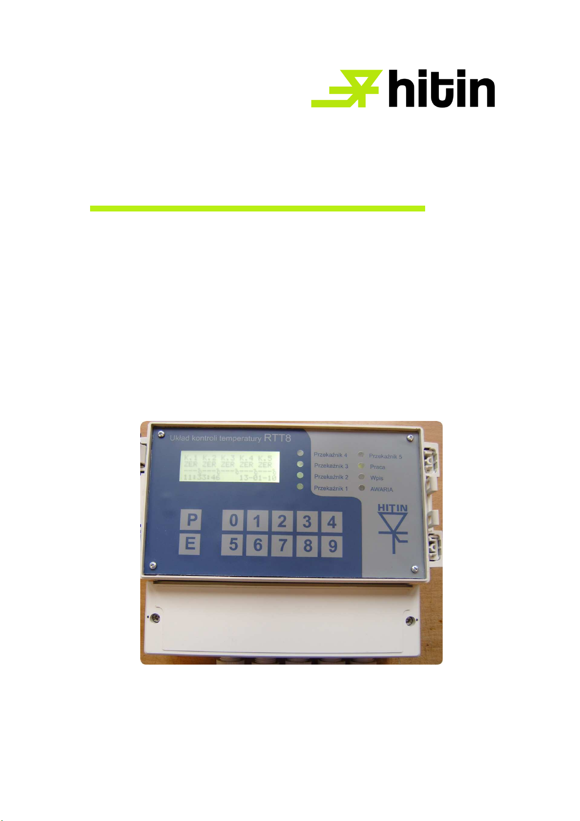
Temperature control relay
RTT8
DTR
Katowice, 2003r.
V27.04.2012

1. Introduction
Electronic device RTT 8 is meant to find out excess temperature of transformers equipped
with PT100 sensors.
2. Use
RTT 8 is dedicated to monitor temperature of both dry and resinblock transformers equipped
with PT100 sensors. It is able to control temperature of up to 5 sensors. The relay with switching
contacts is applied as the device outputs for each temperature threshold.
3. Technical data
Nominal Voltage: 42 – 240 V AC or 42 – 240 V DC without switchings
Maximum absorbed power: 10VA
Number of inputs 5 sensors PT100
Isolation:
Power supply to housing 2,5 kV
Inputs to housing 2,5 kV
Output to housing 2,5 kV
Power supply to output 2,5 kV
Power supply to input 2,5 kV
Input to output 2,5 kV
Protection IP 65
Dimensions 212x216x120 (see dwg.2)
Position of operation any
Weight 1,5 kg
Temperature scale 70°C – 220°C with 1°C resolution
Time relay delay 70s – 220s or 70min. – 220 min.
Operating temperature 0 – 45°C
Storage temperature -25C – 85C
Diameter of linking cables max 2,5 mm
2
Maximum switch current: 8A / 250VAC/24VDC
Maximum switch power: 2kVA / 192W
Maximum switch voltage: 400V AC / 150V DC
Operation in environment free from any inflammable or chemically active dusts and gases is essential.
4. Installation
Fasten the device with three M5 screws through the holes in the bottom part of the housing.
RTT8 ought to be used and kept away from water, conducting or not conducting dusts, explosive,
inflammable and chemically active gases, dusts and vapours. Connect protective earth, power supply,
and the sensors. Connect output contacts as desired. Connect data transfer cables (option).
5. Functioning of the operating programme
After switching on power supply initiation of the display is carried out. Then the internal
system is tested. At the next step the programme is proceeding to verification of the user’s password.
If the password is entered, no changes to the original settings will be possible. After 30 days of
operation all functions of the device will be blocked unless the password is re-entered.
If the password is not entered the programme will start to work with original settings after it has been
switch on for the first time.
If any faults occur (i.e. heavy interference or lack of power supply) the device can return to its
initial settings.

6. Operation
Up to 5 sensors can be connected to the input contacts (always one sensor to one contact!).
The device can be connected with a computer equipped with serial interface RS232. Maximum 255
devices can be connected to one interface.
RTT 8 is equipped with 5 outgoing relays with switching contacts connected to the output
connectors.
At picture 1. the switching connectors have been shown in the power-off position. The condition of the
first three relays (P1, P2, P3) depends on the temperature of the sensors (K1, K2, K3, respectively).
The threshold temperatures TxH and TxL for each relay can be adjusted from the keyboard or an out-
side computer.
If sensor temperature exceeds TxH, relay will be automatically switched off. After the temperature has
dropped below TxL, relay will be switched on again. If the input sensor is short connected or has been
torn out, RTT8 reacts as if the temperature has been exceeded and switches the relay off.
Relay 4.
Functioning of the relay 4 depends on the operating mode set.
In the temperature control mode the relay operates identically to the first three ones (P1,P2,P3,). It
controls sensor K4.
In the maximum temperature control mode the device compares the highest value measured on the
sensors K1, K2 and K3 to the threshold temperatures T4H and T4L, switching relay 4 on or off
respectively.
In the timing mode the relay will be switched on after a desired period. The previously set time
interval is counted down after the testing procedures, initialised when power is on, have been
completed.
Relay 5.
Functioning of the relay 5 depends on the operating mode set.
In the temperature control mode the relay operates identically to the first three ones (P1,P2,P3,). It
controls sensor K5.
In the timing mode relay 5 is being switched off simultaneously with relay 3. Relay 5 will be switched
on after time delay set, counted down from the moment of switching on relay 3.
In the parallel mode relay 5 operates identically to relay 2.
Operation of the relays 4 and 5 is steered by the programme code, which can be modified from the
keyboard or an outside computer.
Relay 5
Relay 4
Display
X.7
X.6
X.5
X.4
X.3
X.2
X.1
X.0
K45=>00000000
X
.7 – not used
X.6 – switches relay 5 to parallel mode
X.5 – switches relay 5 to timing mode (time in min.)
X.4 - switches relay 5 to temperature control mode
X.3 – not used
X.2 – switches relay 4 to maximum temperature control mode
X.1 – switches relay 4 to timing mode (time in sec.)
X.0 – switches relay 4 to temperature control mode
Values X.7 – X.1 can be entered only as 0 or 1. Value 0 switches the respective mode off, whereas
value 1 switches it on.
Programming of the operating mode is being carried out by entering value 0 or 1 in the consecutive
fields. A blinking cursor will be visible on the display under the first digit possible to alter. (K45=> _ -
------ )
“_” indicates current position of the cursor
Any improper values of the programming code K45 will be automatically deleted.

If fields X.7 and X.3 have been filled out with digit 1, both relays (4 and 5) are inactive.
Original configuration of code K45 is set as 0010 0010.
7. Short operation manual.
After power supply has been switched on info about the company is displayed, followed by
the test of the system (after 2 sec.). If no problems are detected the password will be verified. Every
RTT has its own separate password consisting of 4 digits.
The built-in display has 4 lines, 20 digits each.
When the device is working normally, abbreviated information about its operation is being displayed.
Sensor and relay numbers are displayed in the first line.
Information about the condition of the relay and sensor is shown in an abbreviated form in the second
line.
Explanation of the abbreviations used are displayed after entering the key No. 8.
ERR –missing data or error
ZER – sensor has been torn out
ZW – sensor is short connected
WŁ – relay is on
WYŁ – relay is off
TW – time relay is on
TWY – time relay is off
MWŁ – maximum temperature control mode is on
MWY - maximum temperature control mode is off
MER - maximum temperature control mode is malfunctioning
3WŁ – time relay 3 is on
3WY – time relay 3 is off
2WŁ – parallel mode is on
2WY – parallel mode is off
Explanation of the abbreviations not displayed:
TxL – threshold temperature when relay is on
TxH - threshold temperature when relay is off
For relays 4 and 5 following abbreviations are used:
T4L – determined delay for time relay (in sec.)
T5L – determined time relay (in min.)
In the third line current temperature or time (given in sec. or min.) is displayed. If any faults occur
three strokes will be displayed instead of the temperature.
Current time and date is displayed in the fourth line.
After pressing any key MENU is activated. It allows for:
1. Setting the clock
a) press 1
b) when appears menu with on figure blinking grid (1) press (E) to setup a new time and dates or
(P) return to main purpose menu..
Exemplary appearance of display with main menu.

K
. 1 K . 2 K . 3 K . 4 K . 5
W
ł W ł W ł M W ł W y ł
2 4
°
c 2 2
°
c 2 9
°
c 2 9
°
c - 2 4
°
c
1
2 : 3 7 : 5 7 3 1 - 1 1 - 0 5
c) after pressing (E) the field appears there you should set a new time from keyboard. After setup a
new time press (E) to setup a new date.
d) after setup a new date press (E) to save data to memory. Device will inform about saving a date
and it will return to main menu.
2. Changing factory setup.
Change is possible if identify code isn't inscribed.
a) press (2)
b) when appears menu with on figure blinking grid (2) press (E) to setup a new setup or (P) to
return to main menu.
c) after pressing (E) appears the field with factory set data or set from keyboard.
Exemplary appearance of display with factory setup.
K
. 1 K . 2 K . 3 K . 4 K . 5
- - - 1 4 0 1 4 0 1 3 0 1 4 0
1
3 5 1 3 5 1 3 5 1 2 5 1 2 5
K
L U C Z K 4 5 = > 0 1 0 0 0 0 0 1
Blinking cursor (---) define place of inscription a new data. When you finish inscribing a new data and
code will appear question about registration a new data to memory. When you press (E) data will be
save and return to main menu. When you press (P) you return to inscribing a new data.
Appearance of display:
C z y p o d a n e d a n e
Z
a p i s a ćd o p a m i ęc i ?
E - T A K , P - N I E
ATTENTION:
Pressing (E) forces set ALL data with code define in point 4 this instruction.
3. Channel data inspection .
a) press (3)
b) when appears menu with on figure blinking grid (3) press (E) to inspect channel data or (P) to
return main menu.
c) after pressing (E) appears following menu:
k
a n a ł - > 1 s . - > Z E R
t e m
p e r . w y ł . - > 1 4 0
t e m
p e r . w ł . - > 1 3 5
c
. p . 9 9 - 0 9 - 0 1 0 8 : 1 6
Inspection next channel is possible after next pressing (E). The sixth pressing (E) causes automatic
return to main menu.
Displayed date and time at the bottom define last switching of device.
Several control lamps on the front panel inform about operation of the whole system.
5 control lamps for the relays – light indicates that the respective relay is on

green lamp – normal operation
yellow lamp – indicates data transfer to an outside computer
red lamp - error
Dwg. 1. Arrangement of basic elements on the pcb

Dwg.2. Housing dimensions.
7 0
1 2 0
1 8 4
6 0
2 1 2
2 1 6
11

Dwg.3. Typical RTT8 connection by Pt100 sensors

Dwg.4. Position of the mounting holes
197
139
5
Table of contents
Popular Relay manuals by other brands

CleaverBrooks
CleaverBrooks CB780 installation instructions

BIG TREE TECH
BIG TREE TECH Relay V1.2 Operating instruction

Kyongbo Electronics
Kyongbo Electronics GDR-JD01 user manual

PSP
PSP SAK-60 Programming guide

Kyongbo Electric
Kyongbo Electric GDR-M02 user manual

SafeTrust
SafeTrust SABRE INLINE installation guide


