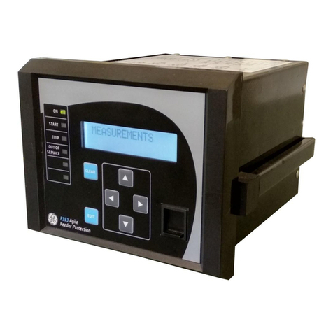
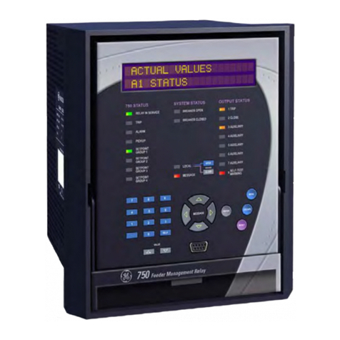
GE ML Series 350 Use and care manual

Communications Guide
3 Series revision: 2.3x
Manual P/N: 1601-0246-A2
GE publication code: GEK-130922A
*1601-0246-A2*
GE
Grid Solutions
3 Series
Protective Relay Platform
350 - 345 - 339
LISTED
52TL
IND.CONT. EQ.
E83849

1-ii SR3 SERIES PROTECTIVE RELAY PLATFORM – COMMUNICATIONS GUIDE
© 2017 GE Multilin Inc. All rights reserved.
GE Grid Solutions 3 Series Protective Relay Platform Communications Guide for revision
2.3x.
3 Series Protective Relay Platform, EnerVista, EnerVista Launchpad, and EnerVista 3 Series
Setup, are trademarks or registered trademarks of GE Multilin Inc.
The contents of this manual are the property of GE Multilin Inc. This documentation is
furnished on license and may not be reproduced in whole or in part without the permission
of GE Multilin. The content of this manual is for informational use only and is subject to
change without notice.
Part number: 1601-0246-A2 (March 2017)
For further assistance
For product support, contact the information and call center as follows:
GE Grid Solutions
650 Markland Street
Markham, Ontario
Canada L6C 0M1
Worldwide telephone: +1 905 927 7070
Europe/Middle East/Africa telephone: +34 94 485 88 54
North America toll-free: 1 800 547 8629
Fax: +1 905 927 5098
Website: http://www.gegridsolutions.com/multilin

SR3 SERIES PROTECTIVE RELAY PLATFORM – COMMUNICATIONS GUIDE 1-iii
Safety words and definitions
The following symbols used in this document indicate the following conditions:
Note Indicates a hazardous situation which, if not avoided, will result in death or serious
injury.
Note Indicates a hazardous situation which, if not avoided, could result in death or serious
injury.
Note Indicates a hazardous situation which, if not avoided, could result in minor or
moderate injury.
Note Indicates practices not related to personal injury.
NOTE
Indicates general information and practices, including operational information and
practices, that are not related to personal injury.

1-iv SR3 SERIES PROTECTIVE RELAY PLATFORM – COMMUNICATIONS GUIDE

SR3 SERIES PROTECTIVE RELAY PLATFORM – COMMUNICATIONS GUIDE v
Table of Contents
1. INTRODUCTION Communications interfaces..........................................................................................1 - 1
2. RS485 INTERFACE Electrical Interface.............................................................................................................2 - 1
MODBUS Protocol ..............................................................................................................2 - 2
Data Frame Format and Data Rate.................................................................................2 - 2
Data Packet Format................................................................................................................2 - 2
Error Checking ...........................................................................................................................2 - 3
CRC-16 Algorithm.....................................................................................................................2 - 3
Timing ............................................................................................................................................2 - 4
3 Series supported functions ..............................................................................................2 - 4
DNP protocol settings......................................................................................................2 - 5
DNP communication...............................................................................................................2 - 5
DNP device profile....................................................................................................................2 - 6
DNP implementation ..............................................................................................................2 - 8
DNP serial EnerVista Setup ..................................................................................................2 - 12
DNP general................................................................................................................................2 - 14
IEC 60870-5-103 serial communication .................................................................2 - 16
Interoperability..........................................................................................................................2 - 16
Physical layer ...........................................................................................................................2 - 16
Link layer ....................................................................................................................................2 - 17
Application layer .....................................................................................................................2 - 17
Application level........................................................................................................................2 - 21
Application functions ............................................................................................................2 - 21
Type identification..................................................................................................................2 - 21
Function type............................................................................................................................2 - 22
Information number..............................................................................................................2 - 22
Data management ..................................................................................................................2 - 23
Digital states .............................................................................................................................2 - 23
Measurands...............................................................................................................................2 - 23
Commands ................................................................................................................................2 - 25
103 general settings ...............................................................................................................2 - 25
3. ETHERNET
INTERFACE
350 Redundancy Options ..............................................................................................3 - 1
350 Parallel Redundancy Protocol (PRP) .......................................................................3 - 3
350 High-availability Seamless Redundancy (HSR).................................................3 - 4
350 Daisy Chain........................................................................................................................3 - 5
350 LLA (Link Loss Alert) ........................................................................................................3 - 6
SNTP .........................................................................................................................................3 - 7
SNTP settings..............................................................................................................................3 - 7
SNTP modes................................................................................................................................3 - 7
MODBUS TCP/IP ..................................................................................................................3 - 8
Data and control functions..................................................................................................3 - 8
Exception and error responses..........................................................................................3 - 9
Request response sequence...............................................................................................3 - 9
DNP Ethernet protocol settings...................................................................................3 - 10
DNP communication...............................................................................................................3 - 10
DNP device profile....................................................................................................................3 - 11
DNP port allocation .................................................................................................................3 - 13
DNP implementation ..............................................................................................................3 - 14

vi SR3 SERIES PROTECTIVE RELAY PLATFORM – COMMUNICATIONS GUIDE
DNP Ethernet EnerVista Setup...........................................................................................3 - 17
DNP general................................................................................................................................3 - 19
IEC60870-5-104 protocol...............................................................................................3 - 22
IEC 60870-5-104 interoperability.....................................................................................3 - 22
IEC 60870-5-104 protocol settings..................................................................................3 - 30
IEC 60870-5-104 point lists .................................................................................................3 - 31
Summary of Ethernet client connections ..............................................................3 - 34
4. 3 SERIES IEC61850
GOOSE
GOOSE configuration via the 3 Series menus ......................................................4 - 2
EnerVista 3 Series Setup software structure...............................................................4 - 3
GOOSE transmission...............................................................................................................4 - 5
GOOSE Rx.....................................................................................................................................4 - 6
GOOSE Rx status ......................................................................................................................4 - 7
GOOSE Rx headers ..................................................................................................................4 - 9
GOOSE receive dataset structure.....................................................................................4 - 10
GOOSE remote inputs ............................................................................................................ 4 - 11
Using the Simplified GOOSE Configurator..............................................................4 - 13
Setting up the GOOSE Configurator................................................................................4 - 14
Connection..................................................................................................................................4 - 16
Configuration.............................................................................................................................4 - 16
Using the IEC 61850 configurator..............................................................................4 - 27
Introduction to the 3 Series IEC61850 Device Configurator ...............................4 - 27
3 Series GOOSE configuration - Lab................................................................................4 - 31
Configuration lab steps........................................................................................................4 - 33
IEC61850 Server.................................................................................................................4 - 46
Functionality .............................................................................................................................. 4 - 48
IEC61850 Configurator....................................................................................................4 - 49
Online and offline setup........................................................................................................4 - 49
IEC 61850 Configurator Details.........................................................................................4 - 51
ICD/CID.........................................................................................................................................4 - 51
Settings........................................................................................................................................4 - 52
Reports.........................................................................................................................................4 - 55
GOOSE reception and GOOSE transmission...............................................................4 - 56
5. 350 OPC–UA
COMMUNICATION
STANDARD
Definitions and Acronyms.............................................................................................5 - 1
OPC–UA Architecture.......................................................................................................5 - 2
OPC-UA Settings.................................................................................................................5 - 2
OPC–UA Server Configuration Data..........................................................................5 - 2
OPC–UA Point Lists............................................................................................................5 - 3
6. USB INTERFACE MODBUS Protocol..............................................................................................................6 - 1
Data Frame Format and Data Rate ................................................................................6 - 1
Data Packet Format................................................................................................................6 - 2
Error Checking...........................................................................................................................6 - 2
CRC-16 Algorithm ....................................................................................................................6 - 2
Timing............................................................................................................................................6 - 3
3 Series supported functions..............................................................................................6 - 4
7. 350 TIME
PROTOCOLS
350 IEC 1588 Precision Time Protocol (PTP) ..........................................................7 - 1
350 Real Time Clock................................................................................................................ 7 - 2

SR3 SERIES PROTECTIVE RELAY PLATFORM – COMMUNICATIONS GUIDE vii
8. MODBUS
FUNCTIONS
Function Code 03H............................................................................................................8 - 1
Function Code 04H............................................................................................................8 - 3
Function Code 05H............................................................................................................8 - 4
Function Code 06H............................................................................................................8 - 9
Function Code 07H............................................................................................................8 - 10
Function Code 08H............................................................................................................8 - 11
Function Code 10H............................................................................................................8 - 11
Performing Commands Using Function Code 10H ..................................................8 - 13
Function Code 42H............................................................................................................8 - 14
Function Code 43H............................................................................................................8 - 14
Error Responses..................................................................................................................8 - 15
9. USING THE
MODBUS USER MAP
MODBUS User Map............................................................................................................9 - 2
10. 339 MODBUS
MEMORY MAP AND
FORMAT CODES
339 MODBUS memory map..........................................................................................10 - 1
339 Format Codes.............................................................................................................10 - 88
11. 345 MODBUS
MEMORY MAP AND
FORMAT CODES
345 MODBUS memory map..........................................................................................11 - 1
345 Format Codes.............................................................................................................11 - 77
12. 350 MODBUS
MEMORY MAP AND
FORMAT CODES
350 MODBUS memory map..........................................................................................12 - 1
350 Format Codes.............................................................................................................12 - 87
A. IEC 61850
IMPLEMENTATION
DETAILS
MICS..........................................................................................................................................A - 1
1 INTRODUCTION......................................................................................................................A - 1
1.1 Logical Nodes List ...........................................................................................................A - 1
2 LOGICAL NODES ....................................................................................................................A - 4
2.1 System Logical Nodes. LN Group: L........................................................................A - 4
2.2 Logical Nodes for protection functions. LN Group:P.......................................A - 5
2.3 Logical Nodes for protection related functions. LN Group: R.....................A - 19
2.4 Logical Nodes for generic references. LN Group: G........................................A - 24
2.5 Logical Nodes for metering and measurement. LN Group: M...................A - 27
2.6 Logical Nodes for switchgear. LN Group: X.........................................................A - 31
3 COMMON DATA CLASS.......................................................................................................A - 32
3.1 Common data class specifications for status information .........................A - 32
3.2 Common data class specifications for measurand information..............A - 37
3.3 Common data class specifications for controllable status informationA - 45
3.4 Common data class specifications for description information...............A - 47
TICS...........................................................................................................................................A - 48
1 Introduction.............................................................................................................................A - 48
2 Implemented IntOp TISSUES ...........................................................................................A - 48
Mandatory Edition 1 Tissues .............................................................................................A - 48
3 Other Implemented TISSUES...........................................................................................A - 50

viii SR3 SERIES PROTECTIVE RELAY PLATFORM – COMMUNICATIONS GUIDE
PICS ..........................................................................................................................................A - 51
1 General......................................................................................................................................A - 51
2 ASCI basic conformance statement............................................................................ A - 52
3 ACSI models conformance statement .......................................................................A - 53
4 ACSI service conformance statement........................................................................A - 55
PIXIT..........................................................................................................................................A - 58
Introduction................................................................................................................................A - 58
PIXIT for Association model................................................................................................. A - 58
PIXIT for Server model............................................................................................................A - 59
PIXIT for Data set model ....................................................................................................... A - 60
PIXIT for Substitution model................................................................................................A - 60
PIXIT for Setting group control model ............................................................................A - 60
PIXIT for Reporting model ....................................................................................................A - 61
PIXIT for Logging model........................................................................................................ A - 61
PIXIT for GOOSE publish model.......................................................................................... A - 62
PIXIT for GOOSE subscribe model ....................................................................................A - 63
PIXIT for GOOSE performance............................................................................................A - 63
PIXIT for Control model..........................................................................................................A - 64
PIXIT for Time synchronisation model ...........................................................................A - 66
PIXIT for File transfer model................................................................................................A - 66
PIXIT for Service tracking model ......................................................................................A - 66
B. WARRANTY AND
REVISION HISTORY
Warranty ...............................................................................................................................B - 1
Change notes ......................................................................................................................B - 1
Manual Revision history........................................................................................................ B - 1

SR3 SERIES PROTECTIVE RELAY PLATFORM – COMMUNICATIONS GUIDE 1-1
SR3 Series Protective Relay Platform
Chapter 1: Introduction
GE
Grid Solutions
Introduction
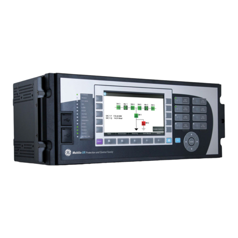
The Multilin 3 Series protective relay platform includes three different relays, the 350, 345,
and 339. Information in this manual applies to all 3 Series relays unless otherwise
indicated.
The 350 is a microprocessor-based relay for primary and backup overcurrent protection of
medium and low voltage distribution feeders. The relay is also suitable for providing
overcurrent and backup protection for small and medium size motors, transformers,
generators, and distribution bus-bars.
The 345 is a microprocessor-based relay for primary and backup protection of small to
medium size distribution transformers. The relay provides advanced algorithms for
automatic magnitude and phase compensation for more than twenty types of two-
winding transformers, good sensitivity for the detection of winding ground faults, and the
flexibility to set any of the phase, ground, neutral and negative sequence currents
overcurrent elements.
The 339 Motor Protection System is a microprocessor based relay providing suitable
protection of medium voltage motors. The basic protection functions of this relay include
motor thermal model, time-delayed and instantaneous overcurrent, ground overcurrent
and sensitive ground overcurrent protection. Additional control features such as logic
control are available for applications that require additional motor control functionality.
Communications interfaces
Each 3 Series relay has three communications interfaces. These can be used
simultaneously:
• RS485
•USB
•Ethernet

1-2 SR3 SERIES PROTECTIVE RELAY PLATFORM – COMMUNICATIONS GUIDE
COMMUNICATIONS INTERFACES CHAPTER 1: INTRODUCTION

SR3 SERIES PROTECTIVE RELAY PLATFORM – COMMUNICATIONS GUIDE 2-1
SR3 Series Protective Relay Platform
Chapter 2: RS485 interface
GE
Grid Solutions
RS485 interface
The hardware or electrical interface in the 3 Series relay is two-wire RS485. In a two-wire
link, data is transmitted and received over the same two wires. Although RS485 two wire
communication is bi-directional, the data is never transmitted and received at the same
time. This means that the data flow is half duplex.
NOTE
NOTE: Polarity is important in RS485 communications. The '+' (positive) terminals of every device
must be connected together.
Electrical Interface
RS485 lines should be connected in a daisy chain configuration with terminating networks
installed at each end of the link (i.e. at the master end and at the slave farthest from the
master). The terminating network should consist of a 120 W resistor in series with a 1 nF
ceramic capacitor when used with Belden 9841 RS485 wire. Shielded wire should always
be used to minimize noise. The shield should be connected to all of the 3 Series relay s as
well as the master, then grounded at one location only. This keeps the ground potential at
the same level for all of the devices on the serial link.

2-2 SR3 SERIES PROTECTIVE RELAY PLATFORM – COMMUNICATIONS GUIDE
MODBUS PROTOCOL CHAPTER 2: RS485 INTERFACE
MODBUS Protocol
The 3 Series relay implements a subset of the Modicon Modbus RTU serial communication
standard. The Modbus protocol is hardware-independent. That is, the physical layer can be
any of a variety of standard hardware configurations. This includes USB, RS485, fibre
optics, etc. Modbus is a single master / multiple slave type of protocol suitable for a multi-
drop configuration.
The 3 Series relay is always a Modbus slave. It can not be programmed as a Modbus
master. Computers or PLCs are commonly programmed as masters.
Both monitoring and control are possible using read and write register commands. Other
commands are supported to provide additional functions.
The Modbus protocol has the following characteristics.
•Address:1to254
• Supported Modbus function codes: 1H, 2H, 3H, 4H, 5H, 6H, 7H, 8H, 10H, 42H, 43H
For details see MODBUS Functions.
Data Frame Format and Data Rate
One data frame of an asynchronous transmission to or from a 3 Series relay typically
consists of 1 start bit, 8 data bits, and 1 stop bit. This produces a 10 bit data frame. This is
important for transmission through modems at high bit rates.
Modbus protocol can be implemented at any standard communication speed. The 3 Series
relay supports operation at 9600, 19200, 38400, 57600, and 115200 baud.
NOTE
NOTE: The USB interface will support only 115200 baud.
Data Packet Format
A complete request/response sequence consists of the following bytes (transmitted as
separate data frames):
Master Request Transmission:
SLAVE ADDRESS: 1 byte
FUNCTION CODE: 1 byte
DATA: variable number of bytes depending on FUNCTION CODE
CRC: 2 bytes
Slave Response Transmission:
SLAVE ADDRESS: 1 byte
FUNCTION CODE: 1 byte
DATA: variable number of bytes depending on FUNCTION CODE
CRC: 2 bytes
SLAVE ADDRESS: This is the first byte of every transmission. This byte represents the user-
assigned address of the slave device that is to receive the message sent by the master.
Each slave device must be assigned a unique address and only the addressed slave will
respond to a transmission that starts with its address. In a master request transmission the
SLAVE ADDRESS represents the address of the slave to which the request is being sent. In a
slave response transmission the SLAVE ADDRESS represents the address of the slave that is
sending the response.
FUNCTION CODE: This is the second byte of every transmission. Modbus defines function
codes of 1 to 127.

CHAPTER 2: RS485 INTERFACE MODBUS PROTOCOL
SR3 SERIES PROTECTIVE RELAY PLATFORM – COMMUNICATIONS GUIDE 2-3
DATA: This will be a variable number of bytes depending on the FUNCTION CODE. This may
be Actual Values, Setpoints, or addresses sent by the master to the slave or by the slave to
the master.
CRC: This is a two byte error checking code.
Error Checking
The RTU version of Modbus includes a two byte CRC-16 (16 bit cyclic redundancy check)
with every transmission. The CRC-16 algorithm essentially treats the entire data stream
(data bits only; start, stop and parity ignored) as one continuous binary number. This
number is first shifted left 16 bits and then divided by a characteristic polynomial
(11000000000000101B). The 16 bit remainder of the division is appended to the end of the
transmission, MSByte first. The resulting message including CRC, when divided by the
same polynomial at the receiver will give a zero remainder if no transmission errors have
occurred.
If a 3 Series relay Modbus slave device receives a transmission in which an error is
indicated by the CRC-16 calculation, the slave device will not respond to the transmission.
A CRC-16 error indicates than one or more bytes of the transmission were received
incorrectly and thus the entire transmission should be ignored in order to avoid the 3
Series relay performing any incorrect operation.
The CRC-16 calculation is an industry standard method used for error detection. An
algorithm is included here to assist programmers in situations where no standard CRC-16
calculation routines are available.
CRC-16 Algorithm
Once the following algorithm is complete, the working register “A” will contain the CRC
value to be transmitted. Note that this algorithm requires the characteristic polynomial to
be reverse bit ordered. The MSBit of the characteristic polynomial is dropped since it does
not affect the value of the remainder. The following symbols are used in the algorithm:
—>: data transfer
A: 16 bit working register
AL: low order byte of A
AH: high order byte of A
CRC: 16 bit CRC-16 value
i, j: loop counters
(+): logical exclusive or operator
Di: i-th data byte (i = 0 to N-1)
G: 16 bit characteristic polynomial = 1010000000000001 with MSbit dropped and bit order
reversed
shr(x): shift right (the LSbit of the low order byte of x shifts into a carry flag, a '0' is shifted
into the MSbit of the high order byte of x, all other bits shift right one location
The algorithm is:
1. FFFF hex —> A
2. 0 —> i
3. 0 —> j

2-4 SR3 SERIES PROTECTIVE RELAY PLATFORM – COMMUNICATIONS GUIDE
MODBUS PROTOCOL CHAPTER 2: RS485 INTERFACE
4. Di (+) AL —> AL
5. j+1 —> j
6. shr(A)
7. is there a carry? No: go to 8. Yes: G (+) A —> A
8. is j = 8? No: go to 5. Yes: go to 9.
9. i+1 —> i
10. is i = N? No: go to 3. Yes: go to 11.
11. A —> CRC
Timing
Data packet synchronization is maintained by timing constraints. The receiving device
must measure the time between the reception of characters. If 3.5 character times elapse
without a new character or completion of the packet, then the communication link must
be reset (i.e. all slaves start listening for a new transmission from the master). Thus at
115200 baud a delay of greater than 3.5 x 1 / 115200 x 10 x = 0.3 ms will cause the
communication link to be reset.
3 Series supported functions
The following functions are supported by the 3 Series relay :
• FUNCTION CODE 03H - Read Setpoints
• FUNCTION CODE 04H - Read Actual Values
• FUNCTION CODE 05H - Execute Operation
• FUNCTION CODE 06H - Store Single Setpoint
• FUNCTION CODE 07H - Read Device Status
• FUNCTION CODE 08H - Loopback Test
• FUNCTION CODE 10H - Store Multiple Setpoints
Refer to section 6 of this guide for more details on MODBUS function codes.

CHAPTER 2: RS485 INTERFACE DNP PROTOCOL SETTINGS
SR3 SERIES PROTECTIVE RELAY PLATFORM – COMMUNICATIONS GUIDE 2-5
DNP protocol settings
DNP communication
The menu structure for the DNP protocol is shown below.
Figure 2-1: DNP communication menu
The following path is available using the keypad.
PATH: SETPOINTS > S1 RELAY SETUP > COMMUNICATIONS > DNP PROTOCOL > DNP GENERAL
S1 DNP GENERAL
DNP ADDRESS
DNP TCP/UDP PORT
CHANNEL 1 PORT
CHANNEL 2 PORT
TME SYNC IIN PER.
DNP MSG FRAG SIZE
DNP TCP CONN. T/O
FAULT REP MAPPING
ٕ
S1 DNP
DNP GENERAL
DNP UNSOL RESPONSE*
DEFAULT VARIATION
DNP CLIENT ADDRESS*
DNP POINTS LIST
ٕ
898769A2.cdr
DNP CLIENT ADDRESS*
CLIENT ADDRESS 1
ٕ
CLIENT ADDRESS 2
CLIENT ADDRESS 3
CLIENT ADDRESS 4
CLIENT ADDRESS 5
POINT 0
...
ٕ
POINT 1
POINT 2
POINT 63
S1 DNP POINTS LIST
BINARY INPUTS
BINARY OUTPUTS
ANALOG INPUTS
POINT 0 ENTRY
POINT 1
POINT 2
...
POINT 31
ٕ
ENTRY
ENTRY
ENTRY
POINT 0 ON
POINT 0 OFF
POINT 1 ON
POINT 1 OFF
...
POINT 15 ON
POINT 15 OFF
ٕ
DEFAULT VARIATION
DNP OBJECT 1
ٕ
DNP OBJECT 2
DNP OBJECT 20
DNP OBJECT 21
DNP OBJECT 22
DNP OBJECT 23
DNP OBJECT 30
DNP OBJECT 32
DNP UNSOL RESPONSE*
FUNCTION
ٕ
TIMEOUT
MAX RETRIES
DEST ADDRESS
* Ethernet only

2-6 SR3 SERIES PROTECTIVE RELAY PLATFORM – COMMUNICATIONS GUIDE
DNP PROTOCOL SETTINGS CHAPTER 2: RS485 INTERFACE
To view the list of DNP Binary Inputs please refer to the Format Codes section - FC134B - of
this Guide.
DNP device profile
DNP 3.0 Device Profile
(Also see the IMPLEMENTATION TABLE in the following section)
Vendor Name: General Electric Multilin
Device Name: 3 Series relay
Highest DNP Level Supported:
For Requests: Level 2
For Responses: Level 2
Device Function:
□Master
⊠Slave
Notable objects, functions, and/or qualifiers supported in addition to the Highest DNP Levels
Supported (the complete list is described in the attached table):
Binary Inputs (Object 1)
Binary Input Changes (Object 2)
Binary Outputs (Object 10)
Control Relay Output Block (Object 12)
Binary Counters (Object 20)
Frozen Counters (Object 21)
Counter Change Event (Object 22)
Frozen Counter Event (Object 23)
Analog Inputs (Object 30)
Analog Input Changes (Object 32)
Analog Deadbands (Object 34)
Time and Date (Object 50)
Internal Indications (Object 80)
Maximum Data Link Frame Size (octets): Maximum Application Fragment Size (octets):
Transmitted: 292 Transmitted: configurable up to 2048
Received: 292 Received: 2048
Maximum Data Link Re-tries: Maximum Application Layer Re-tries:
⊠None ⊠None
□Fixed at 3 □Configurable
□Configurable
Requires Data Link Layer Confirmation:
⊠Never
□Always
□Sometimes

CHAPTER 2: RS485 INTERFACE DNP PROTOCOL SETTINGS
SR3 SERIES PROTECTIVE RELAY PLATFORM – COMMUNICATIONS GUIDE 2-7
□Configurable
Requires Application Layer Confirmation:
□Never
□Always
⊠When reporting Event Data
⊠When sending multi-fragment responses
□Sometimes
□Configurable
Timeouts while waiting for:
Data Link Confirm: ⊠None □Fixed □Variable □Configurable
Complete Appl. Fragment: ⊠None □Fixed □Variable □Configurable
Application Confirm: □None ⊠Fixed at 10 s □Variable □Configurable
Complete Appl. Response: ⊠None □Fixed at ___ □Variable □Configurable
Others:
Transmission Delay: No intentional delay
Need Time Interval: Configurable (default = 24 hrs.)
Select/Operate Arm Timeout: 10 s
Binary input change scanning period: 8 times per power system cycle
Analog input change scanning period: 500 ms
Counter change scanning period: 500 ms
Frozen counter event scanning period: 500 ms
Sends/Executes Control Operations:
WRITE Binary Outputs ⊠Never □Always □Sometimes □Configurable
SELECT/OPERATE □Never ⊠Always □Sometimes □Configurable
DIRECT OPERATE □Never ⊠Always □Sometimes □Configurable
DIRECT OPERATE – NO ACK □Never ⊠Always □Sometimes □Configurable
Count > 1 ⊠Never □Always □Sometimes □Configurable
Pulse On □Never □Always ⊠Sometimes □Configurable
Pulse Off □Never □Always ⊠Sometimes □Configurable
Latch On □Never □Always ⊠Sometimes □Configurable
Latch Off □Never □Always ⊠Sometimes □Configurable
Queue ⊠Never □Always □Sometimes □Configurable
Clear Queue ⊠Never □Always □Sometimes □Configurable
Explanation of ‘Sometimes’: Object 12 points are mapped to Virtual Inputs and Commands (Force
Coils). Both “Pulse On” and “Latch On” operations perform the same function in the 3 Series relay ;
that is, the appropriate Virtual Input or Coil is put into the “On” state. The On/Off times and Count
value are ignored. “Pulse Off” and “Latch Off” operations put the appropriate Virtual Input or Coil into
the “Off” state. “Trip” and “Close” operations both put the appropriate Virtual Input or coil into the
“On” state if a paired mapping is set, otherwise “Trip” will put into “Off” and “Close” will put into “On”.
Reports Binary Input Change Events when no
specific variation requested:
Reports time-tagged Binary Input Change
Events when no specific variation
requested:
□Never □Never
⊠Only time-tagged ⊠Binary Input Change With Time
□Only non-time-tagged □Binary Input Change With Relative Time
□Configurable □Configurable (attach explanation)
Sends Unsolicited Responses: Sends Static Data in Unsolicited Responses:
□Never ⊠Never
□Configurable □When Device Restarts
DNP 3.0 Device Profile

2-8 SR3 SERIES PROTECTIVE RELAY PLATFORM – COMMUNICATIONS GUIDE
DNP PROTOCOL SETTINGS CHAPTER 2: RS485 INTERFACE
DNP implementation
□Only certain objects □When Status Flags Change
⊠Sometimes No other options are permitted.
⊠ENABLE/DISABLE unsolicited Function codes
supported
Explanation of ‘Sometimes’: It will be disabled for
RS-485 applications, since there is no collision
avoidance mechanism. For Ethernet communication
it will be available and it can be disabled or enabled
with the proper function code.
Default Counter Object/Variation: Counters Roll Over at:
□No Counters Reported □No Counters Reported
□Configurable (attach explanation) □Configurable (attach explanation)
⊠Default Object: 20 ⊠16 Bits
Default Variation: 1
⊠Point-by-point list attached □Other Value: _____
⊠Point-by-point list attached
Sends Multi-Fragment Responses:
⊠Yes
□No
DNP 3.0 Device Profile
OBJECT REQUEST RESPONSE
OBJECT
NO.
VARIATION
NO.
DESCRIPTION FUNCTION
CODES (DEC)
QUALIFIER CODES
(HEX)
FUNCTION
CODES (DEC)
QUALIFIER CODES
(HEX)
1 0 Binary Input (Variation 0 is
used to request default
variation)
1 (read) 22
(assign class) 00, 01 (start-stop) 06
(no range, or all) 07,
08 (limited quantity)
17, 28 (index)
--- ---
1 Binary Input 1 (read) 22
(assign class) 00, 01 (start-stop) 06
(no range, or all) 07,
08 (limited quantity)
17, 28 (index)
129 (response) 00, 01 (start-stop)
17, 28 (index) (see
Note 2)
2 Binary Input with Status 1 (read) 22
(assign class) 00, 01 (start-stop) 06
(no range, or all) 07,
08 (limited quantity)
17, 28 (index)
129 (response) 00, 01 (start-stop)
17, 28 (index) (see
Note 2)
2 0 Binary Input Change
(Variation 0 is used to
request default variation)
1 (read) 06 (no range, or all)
07, 08 (limited
quantity)
--- ---
1 Binary Input Change
without Time 1 (read) 06 (no range, or all)
07, 08 (limited
quantity)
129 (response)
130 (unsol.
resp.)
17, 28 (index)
2 Binary Input Change with
Time 1 (read) 06 (no range, or all)
07, 08 (limited
quantity)
129 (response)
130 (unsol.
resp.)
17, 28 (index)
3 Binary Input Change with
Relative Time 1 (read) 06 (no range, or all)
07, 08 (limited
quantity)
--- ---
10 0 Binary Output Status
(Variation 0 is used to
request default variation)
1 (read) 00, 01(start-stop) 06
(no range, or all) 07,
08 (limited quantity)
17, 28 (index)
--- ---
2 Binary Output Status 1 (read) 00, 01 (start-stop) 06
(no range, or all) 07,
08 (limited quantity)
17, 28 (index)
129 (response) 00, 01 (start-stop)
17, 28 (index) (see
Note 2)

CHAPTER 2: RS485 INTERFACE DNP PROTOCOL SETTINGS
SR3 SERIES PROTECTIVE RELAY PLATFORM – COMMUNICATIONS GUIDE 2-9
12 1 Control Relay Output Block 3 (select)4
(operate) 5 (direct
op) 6 (dir. op,
noack)
00, 01 (start-stop)
07, 08 (limited
quantity) 17, 28
(index)
129 (response) echo of request
20 0 Binary Counter (Variation 0
is used to request default
variation)
1 (read) 7 (freeze)
8 (freeze noack) 9
(freeze clear) 10
(frz. cl. noack) 22
(assign class)
00, 01 (start-stop) 06
(no range, or all) 07,
08 (limited quantity)
17, 28 (index)
--- ---
1 32-Bit Binary Counter 1 (read)7 (freeze)
8 (freeze noack) 9
(freeze clear) 10
(frz. cl. noack) 22
(assign class)
00, 01 (start-stop) 06
(no range, or all) 07,
08 (limited quantity)
17, 28 (index)
129 (response) 00, 01 (start-stop)
17, 28 (index) (see
Note 2)
2 16-Bit Binary Counter 1 (read) 7 (freeze)
8 (freeze noack) 9
(freeze clear) 10
(frz. cl. noack) 22
(assign class)
00, 01 (start-stop) 06
(no range, or all) 07,
08 (limited quantity)
17, 28 (index)
129 (response) 00, 01 (start-stop)
17, 28 (index) (see
Note 2)
5 32-Bit Binary Counter
without Flag 1 (read) 7 (freeze)
8 (freeze noack) 9
(freeze clear) 10
(frz. cl. noack) 22
(assign class)
00, 01 (start-stop) 06
(no range, or all) 07,
08 (limited quantity)
17, 28 (index)
129 (response) 00, 01 (start-stop)
17, 28 (index) (see
Note 2)
6 16-Bit Binary Counter
without Flag 1 (read) 7 (freeze)
8 (freeze noack) 9
(freeze clear) 10
(frz. cl. noack) 22
(assign class)
00, 01 (start-stop) 06
(no range, or all) 07,
08 (limited quantity)
17, 28 (index)
129 (response) 00, 01 (start-stop)
17, 28 (index) (see
Note 2)
21 0 Frozen Counter(Variation 0
is used to request
defaultvariation)
1 (read) 22
(assign class) 00, 01 (start-stop) 06
(no range, or all) 07,
08 (limited quantity)
17, 28 (index)
--- ---
1 32-Bit Frozen Counter 1 (read) 22
(assign class) 00, 01 (start-stop) 06
(no range, or all) 07,
08 (limited quantity)
17, 28 (index)
129 (response) 00, 01 (start-stop)
17, 28 (index) (see
Note 2)
2 16-Bit Frozen Counter 1 (read) 22
(assign class) 00, 01 (start-stop) 06
(no range, or all) 07,
08 (limited quantity)
17, 28 (index)
129 (response) 00, 01 (start-stop)
17, 28 (index) (see
Note 2)
9 32-Bit Frozen Counter
without Flag 1 (read) 22
(assign class) 00, 01 (start-stop) 06
(no range, or all) 07,
08 (limited quantity)
17, 28 (index)
129 (response) 00, 01 (start-stop)
17, 28 (index) (see
Note 2)
10 16-Bit Frozen Counter
without Flag 1 (read) 22
(assign class) 00, 01 (start-stop) 06
(no range, or all) 07,
08 (limited quantity)
17, 28 (index)
129 (response) 00, 01 (start-stop)
17, 28 (index) (see
Note 2)
22 0 Counter Change Event
(Variation 0 is used to
request default variation)
1 (read) 06 (no range, or all)
07, 08 (limited
quantity)
--- ---
1 32-Bit Counter Change
Event 1 (read) 06 (no range, or all)
07, 08 (limited
quantity)
129 (response)
130 (unsol.
resp.)
17, 28 (index)
2 16-Bit Counter Change
Event 1 (read) 06 (no range, or all)
07, 08 (limited
quantity)
129 (response)
130 (unsol.
resp.)
17, 28 (index)
5 32-Bit Counter Change
Event with Time 1 (read) 06 (no range, or all)
07, 08 (limited
quantity)
129 (response)
130 (unsol.
resp.)
17, 28 (index)
OBJECT REQUEST RESPONSE
OBJECT
NO.
VARIATION
NO.
DESCRIPTION FUNCTION
CODES (DEC)
QUALIFIER CODES
(HEX)
FUNCTION
CODES (DEC)
QUALIFIER CODES
(HEX)

2-10 SR3 SERIES PROTECTIVE RELAY PLATFORM – COMMUNICATIONS GUIDE
DNP PROTOCOL SETTINGS CHAPTER 2: RS485 INTERFACE
6 16-Bit Counter Change
Event with Time 1 (read) 06 (no range, or all)
07, 08 (limited
quantity)
129 (response)
130 (unsol.
resp.)
17, 28 (index)
23 0 Frozen Counter Event
(Variation 0 is used to
request default variation)
1 (read) 06 (no range, or all)
07, 08 (limited
quantity)
--- ---
1 32-Bit Frozen Counter Event 1 (read) 06 (no range, or all)
07, 08 (limited
quantity)
129 (response)
130 (unsol.
resp.)
17, 28 (index)
2 16-Bit Frozen Counter Event 1 (read) 06 (no range, or all)
07, 08 (limited
quantity)
129 (response)
130 (unsol.
resp.)
17, 28 (index)
5 32-Bit Frozen Counter Event
with Time 1 (read) 06 (no range, or all)
07, 08 (limited
quantity)
129 (response)
130 (unsol.
resp.)
17, 28 (index)
6 16-Bit Frozen Counter Event
with Time 1 (read) 06 (no range, or all)
07, 08 (limited
quantity)
129 (response)
130 (unsol.
resp.)
17, 28 (index)
30 0 Analog Input (Variation 0 is
used to request default
variation)
1 (read) 22
(assign class) 00, 01 (start-stop) 06
(no range, or all) 07,
08 (limited quantity)
17, 28 (index)
--- ---
1 32-Bit Analog Input 1 (read) 22
(assign class) 00, 01 (start-stop) 06
(no range, or all) 07,
08 (limited quantity)
17, 28 (index)
129 (response) 00, 01 (start-stop)
17, 28 (index) (see
Note 2)
2 16-Bit Analog Input 1 (read) 22
(assign class) 00, 01 (start-stop) 06
(no range, or all) 07,
08 (limited quantity)
17, 28 (index)
129 (response) 00, 01 (start-stop)
17, 28 (index) (see
Note 2)
3 32-Bit Analog Input without
Flag 1 (read) 22
(assign class) 00, 01 (start-stop) 06
(no range, or all) 07,
08 (limited quantity)
17, 28 (index)
129 (response) 00, 01 (start-stop)
17, 28 (index) (see
Note 2)
4 16-Bit Analog Input without
Flag 1 (read) 22
(assign class) 00, 01 (start-stop) 06
(no range, or all) 07,
08 (limited quantity)
17, 28 (index)
129 (response) 00, 01 (start-stop)
17, 28 (index) (see
Note 2)
32 0 Analog Change Event
(Variation 0 is used to
request default variation)
1 (read) 06 (no range, or all)
07, 08 (limited
quantity)
--- ---
1 32-Bit Analog Change Event
without Time 1 (read) 06 (no range, or all)
07, 08 (limited
quantity)
129 (response)
130 (unsol.
resp.)
17, 28 (index)
2 16-Bit Analog Change Event
without Time 1 (read) 06 (no range, or all)
07, 08 (limited
quantity)
129 (response)
130 (unsol.
resp.)
17, 28 (index)
3 32-Bit Analog Change Event
with Time 1 (read) 06 (no range, or all)
07, 08 (limited
quantity)
129 (response)
130 (unsol.
resp.)
17, 28 (index)
4 16-Bit Analog Change Event
with Time 1 (read) 06 (no range, or all)
07, 08 (limited
quantity)
129 (response)
130 (unsol.
resp.)
17, 28 (index)
34 0 Analog Input Reporting
Deadband (Variation 0 is
used to request
defaultvariation)
1 (read) 00, 01 (start-stop) 06
(no range, or all) 07,
08 (limited quantity)
17, 28 (index)
--- ---
1 16-bit Analog Input
Reporting Deadband
(default - see Note 1)
1 (read) 00, 01 (start-stop) 06
(no range, or all) 07,
08 (limited quantity)
17, 28 (index)
129 (response) 00, 01 (start-stop)
17, 28 (index) (see
Note 2)
OBJECT REQUEST RESPONSE
OBJECT
NO.
VARIATION
NO.
DESCRIPTION FUNCTION
CODES (DEC)
QUALIFIER CODES
(HEX)
FUNCTION
CODES (DEC)
QUALIFIER CODES
(HEX)
Other manuals for ML Series 350
3
This manual suits for next models
2
Table of contents
Other GE Relay manuals