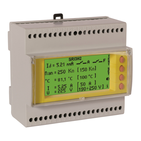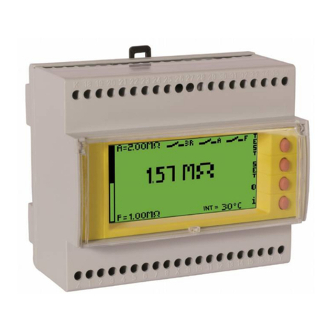
DESCRIZIONE E FUNZIONAMENTO
I sorvegliatori di isolamento SRI3D2 consentono di monitorare continuamente lo
stato delle reti con neutro isolato da terra (sistemi IT). Gli strumenti sono in grado di
rilevare difetti di isolamento dovuti alla componente resistiva anche in presenza di
tensioni continue parassite. I dispositivi offrono 2 livelli differenziati di segnalazione.
La misura di resistenza di isolamento viene effettuata mediante l'applicazione di
una tenzione alternata con ampiezza minore di 20Vp-p (conformemente alla
IEC61557-8) a frequenza auto-adattante.
PRESCRIZIONI DI SICUREZZA E INSTALLAZIONE
Tutte le operazioni di installazione e manutenzione devono essere eseguite da
personale qualificato, in assenza di tensione ed in totale regime di sicurezza
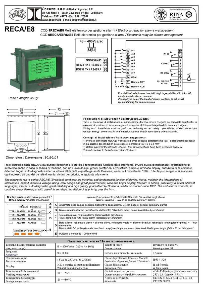
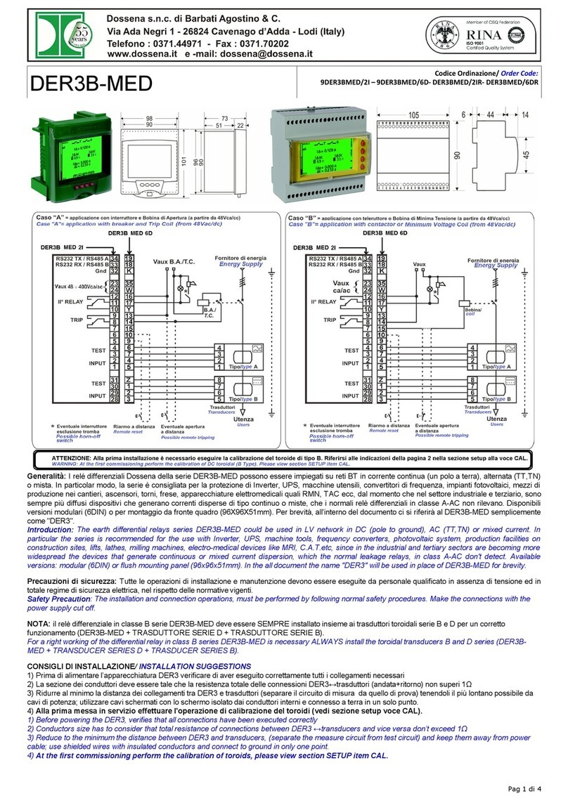
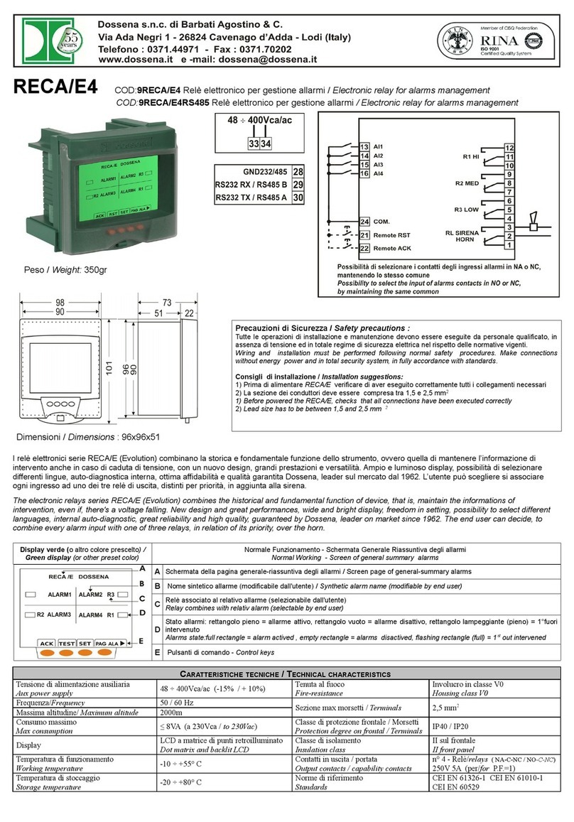
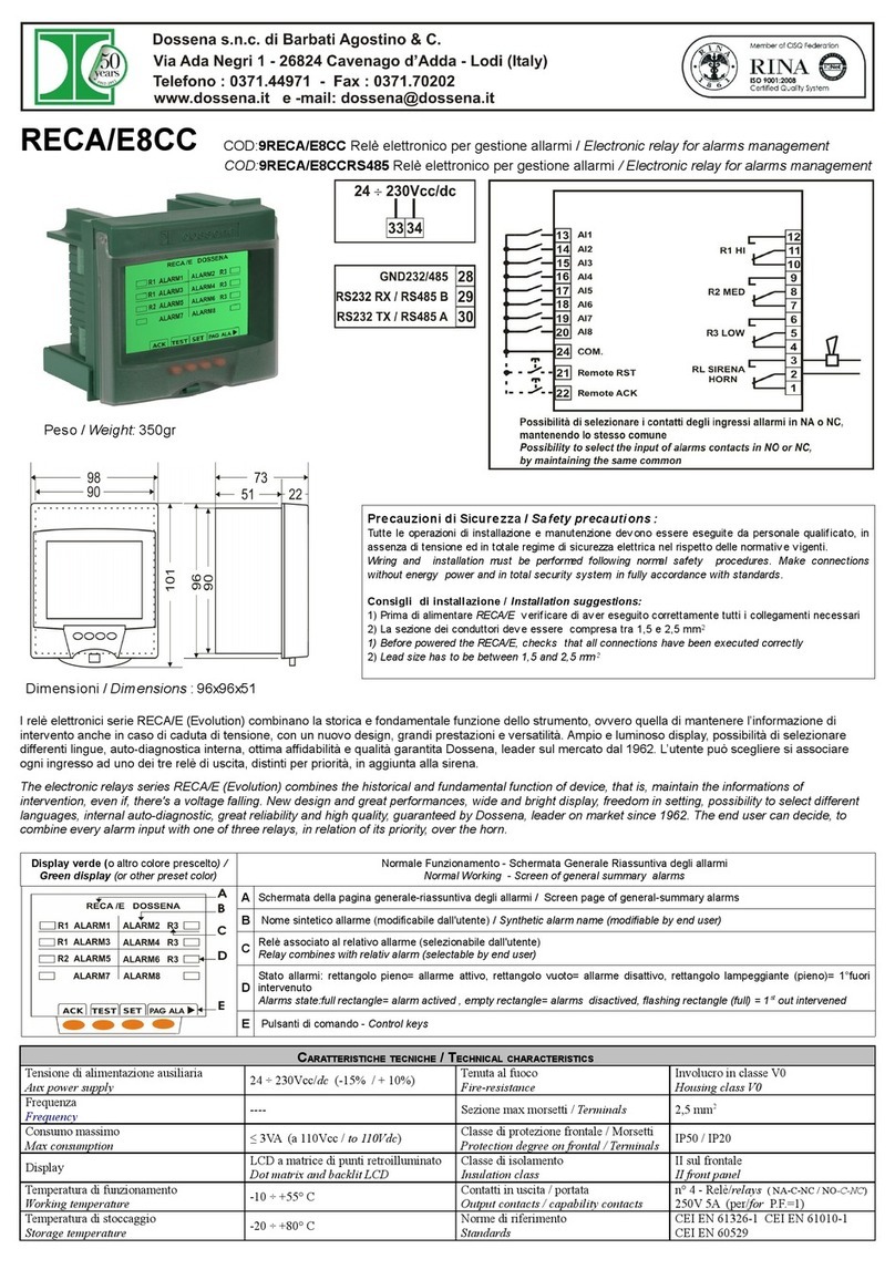
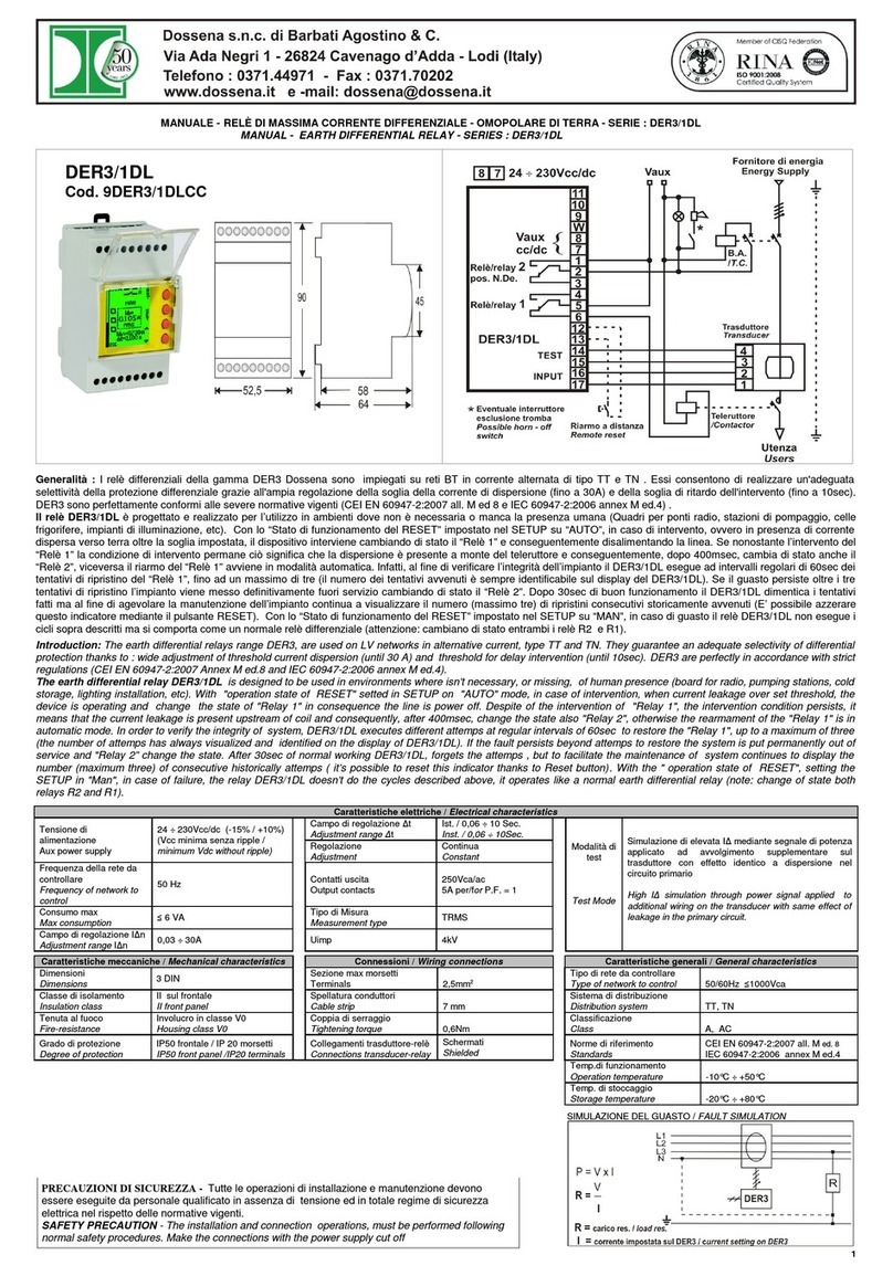
elettrica, nel rispetto delle normative vigenti. Vedere le figure in prima pagina FIG3 e
FIG4 per la corretta installazione.
-Prima di alimentare l'apparecchio verificare di aver eseguito correttamente tutti i
collegamenti necessari.
-La sezione dei cavi deve esser compresa tra 1 e 2,5mm
2
.
APPLICAZIONE SPECIALE
Si può utilizzare il sorvegliatore SRI3 D2 in applicazioni su reti TT/TN in casi in cui
(vedere FIG.5) si abbiano carichi a funzionamento intermittente facendo in modo
che entri in funzione o si attivi la vigilanza del SRI3 solo nel momento della
completa disconnessione dalla rete del dispositivo da vigilare e si disalimenti o si
disattivi la vigilanza nel momento di funzionamento (esempio compressori, celle
frigorifere etc.)
DESCRIPTION AND OPERATION MODE
The relays for permanent control of insulation SRI3/D2 monitors continuously the
status of networks with neutral to ground (IT systems). The instruments can detect
insulation faults due to the resistive components, even in the presence of
continuous parasitic tensions. The devices are able to give two different levels of
signalling. The insulation resistance measurement is performed by applying an
alternating voltage of less than 20Vp-p (conforms to IEC61557-8) in a self-adaptive
frequency.
INSTALLATION AND SAFETY PRECAUTION
All installation and maintenance operations must be performed by qualified
personnel, in the absence of voltage and total electrical safety system, in
compliance with the regulations. See the picture on the first page FIG3 and FIG4 for
a right installation.
- Before powering the equipment, check that you have correctly performed all the
necessary connections.
- The conductors section must be between 1.5 and 2.5mm
2
.
SPECIAL APPLICATION
The SRI3 D2 can be used in applications on TT/TN networks in cases where (see
FIG.5) there are intermittent loads so that the supervision of the SRI3 is activated
only when the device is completely disconnected from the network and the
supervision is deactivated at the time of operation (eg compressors, cold rooms
etc.)
MESSA IN SERVIZIO
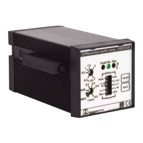
Alla messa in servizio del dispositivo, il led ON si accende (colore verde), indicando
l'operatività dell'apparato. Premendo per almeno 5 secondi il pulsante TEST
avviene l'accensione dei led Alarm e Pre-Alarm e il cambio di stato dei relativi relè.
Rilasciandolo, il led Pre-Alarm si spegne mentre il led di Alarm rimane illuminato,
qualora il reset sia impostato sulla modalità MAN. Premendo il tasto di RESET si
riporta l'apparato alle condizioni iniziali. Se invece il RESET è impostato su AUTO, il
relè di Alarm ritornerà a riposo automaticamente, non appena si rilascia del tasto di
TEST. Le soglie devono essere impostate in relazione delle condizioni di impianto.
Si consiglia di impostare la soglia di Pre-Alarm ad un valore ragionevolmente più
alto di quello impostato per Alarm. Da questo momento il controllo dell'isolamento
può essere affidato al sorvegliatore SRI3/D2. Se la resistenza di isolamento scende
sotto il valore di preallarme impostato si accende il led di Pre-Alarm e commuta il
contatto di Pre-Alarm. Se la resistenza d'isolamento diviene inferiore al valore
impostato di Alarm, il led Alarm si illumina e commuta anche il contatto di Alarm.
ATTENZIONE: dopo l'installazione e dal momento della messa in servizio l'unica
parte accessibile all'utente deve essere il frontale corredato di vetrino apribile, in
quanto il prodotto deve essere montato in un quadro elettrico specificatamente
progettato per gli apparati da barra DIN .
COMMISSIONING
When the device is put into service, the ON led lights up (green),by indicating the
operation of the device. By pressing the TEST button for at least 5 seconds the leds
of Alarm and Pre-Alarm will light on and theirs relays change status, and by
releasing the button, the Pre-Alarm led turns off, but the Alarm led remains powered
if the reset is set to MAN mode. By pressing the RESET button the device will
return the to its initial conditions. If the RESET is set to AUTOmode, the Alarm relay
will return automatically to rest as soon as you release the TEST button . The
thresholds must be set in relation to system conditions. We recommend setting the
pre-alarm threshold to a reasonably higher value than the one set for the alarm.
From this moment the insulation monitoring can be given to the surveyor SRI3/D2.
If the insulation resistance falls below the value of set alarm, the led of
Pre-Alarm turns on and the contact of Pre-Alarm switches. If the insulation
resistance falls below the set value for Alarm, the Alarm LED lights up and also
switches the Alarm contact.
ATTENTION: After installation and commissioning the only part accessible for the
user must be the front glass of device. The product must be installed on electric
panel board specifically designed for DIN rail devices.
ANOMALIE DI FUNZIONAMENTO
1) Non si accende il led ON --> Controllare la presenza di alimentazione ausiliaria e
verificare l'esatto collegamento.
2) Uno o entrambi i relé del SRI3 D2 non intervengono al valore impostato-->
Premere il tasto TEST, se il led id allarme si illumina il sorvegliatore sta
funzionando, quindi l'anomalia va ricercata sull'inserzione del sorvegliatore o in un
guasto dell'apparato.
3) Segnalazione di Pre-Alarm accesa ma senza alcun intervento del relé-->
Staccare i collegamenti ai morsetti 7-8-9 e verificare, ad apparecchio non
alimentato la continuità tra 7-8. Alimentare nuovamente il sorvegliatore, premere il
tasto TEST e verificare la continuità tra i morsetti 8-9. In caso contrario è da
considerarsi come guasto dell'apparecchio. Contattare la sede Dossena per un
controllo tecnico dello strumento.
4) Segnalazione di Alarm accesa ma senza alcun intervento del relé--> Staccare i
collegamenti ai morsetti 10-11-12 e verificare, ad apparecchio non alimentato la
continuità tra 10 e 11. Alimentare nuovamente il sorvegliatore, premere il tasto
TEST e verificare la continuità tra i morsetti 11 e 12. In caso contrario è da
considerarsi come guasto dell'apparecchio. Contattare la sede Dossena per un
controllo tecnico dello strumento.
TROUBLESHOOTING
1) The led ON doesn't switch on →Check the presence of auxiliary power supply of
device and verify the right connections.
2) One or both relays SRI3/D2 don't interven at the set value →Push the TEST
button, if the Alarm led is switching on, the surveyor is working, so the anomaly is to
be found on the insertion of surveyor, or in a damage of apparatus.
3) Pre-alarm signal on, but without any relay intervention -> Remove the wiring on
terminals 7-8-9 and check the continuity between 7-8 with the device not powered.
Power on the surveyor again, press the TEST button and check continuity between
terminals 8-9. Otherwise it is to be considered as a device failure. Contact the
Dossena office for a technical check of the instrument.
4) Alarm signal on, but without any relay intervention : →Remove the wiring on
terminals 10-11-12 and check the continuity between 10-11. Power on the surveyor
again, press the TEST button and check continuity between terminals 12-11.
Otherwise it is to be considered as a device failure. Please contact Dossena for
technical check of the instrument.
