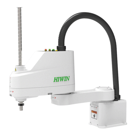
Hiwin RS403 User manual

www.hiwin.tw
User Manual
SCARA Robot
- RS403

INDUSTRIE 4.0 Best Partner
Multi Axis Robot
Pick-and-place / Assembly /
Array and packaging / Semiconductor /
Electro-Optical industry /
Automotive industry / Food industry
• Articulated Robot
• Delta Robot
• SCARA Robot
• Wafer Robot
• Electric Gripper
• Integrated Electric Gripper
• Rotary Joint
Single Axis Robot
Precision / Semiconductor /
Medical / FPD
• KK, SK
• KS, KA
• KU, KE, KC
Direct Drive
Rotary Table
Aerospace / Medical / Automotive industry /
Machine tools / Machinery industry
• RAB Series
• RAS Series
• RCV Series
• RCH Series
Ballscrew
Precision Ground / Rolled
• Super S series
• Super T series
• Mini Roller
• Ecological & Economical
lubrication Module E2
• Rotating Nut (R1)
• Energy-Saving & Thermal-
Controlling (C1)
• Heavy Load Series (RD)
• Ball Spline
Linear Guideway
Automation / Semiconductor / Medical
• Ball Type--HG, EG, WE, MG, CG
• Quiet Type--QH, QE, QW, QR
• Other--RG, E2, PG, SE, RC
Medical Equipment
Hospital / Rehabilitation centers /
Nursing homes
• Robotic Gait Training System
• Hygiene System
• Robotic Endoscope Holder
Bearing
Machine tools / Robot
• Crossed Roller Bearings
• Ball Screw Bearings
• Linear Bearing
• Support Unit
AC Servo Motor & Drive
Semiconductor / Packaging machine
/SMT / Food industry / LCD
• Drives-D1, D1-N, D2
• Motors-50W~2000W
Driven Tool Holders
All kinds of turret
• VDI Systems
Radial Series, Axial Series, MT
• BMT Systems
DS, NM, GW, FO, MT, OM, MS
Linear Motor
Automated transport / AOI application
/ Precision / Semiconductor
• Iron-core Linear Motor
• Coreless Linear Motor
• Linear Turbo Motor LMT
• Planar Servo Motor
• Air Bearing Platform
• X-Y Stage
• Gantry Systems
Torque Motor
(Direct Drive Motor)
Inspection / Testing equipment /
Machine tools / Robot
• Rotary Tables-TMS,TMY,TMN
• TMRW Series
• TMRI Series
II
C07UE001-1804
Company: HIWIN Technologies Corp.
Address: No.7, Jingke Road, Taichung Precision Machinery Park,
Taichung 40852, Taiwan
Date: November 2017
Version: 2.0
Tel: +886-4-23594510
Fax: +886-4-23594420
E-mail: business@hiwin.tw
Website: http://www.hiwin.tw
Copyright: The contents in this manual are used for the authorized customers and
suppliers. This manual should not be copied, reproduced, transmitted in any form or
distributed on Internet without HIWIN’s authorization.
All Rights Reserved
© HIWIN Technologies Corp. All rights reserved

III
C07UE001-1804
Revision History
Version
Date
Remark
Ver1.0
2017/08
First issuance
Ver1.1
2017/11
Added the Ball Screw /Spline
lubrication
Ver1.2
2018/04
Added End-extending load

IV
C07UE001-1804
Table of Content
Table of Content.......................................................................................................IV
Foreword....................................................................................................................6
About Manual ............................................................................................................6
Warranty.....................................................................................................................7
Notice Symbol ...........................................................................................................8
Contact.......................................................................................................................9
Customer Service.......................................................................................................9
About Safety ............................................................................................................10
1 About Safety.........................................................................................................11
1-1 Operation .....................................................................................................11
1-2 Safety Symbol..............................................................................................12
1-3 Operation Notice..........................................................................................14
1-3-1 Run Alert Area........................................................................................14
1-3-2 Temperature Error ..................................................................................14
1-3-3 Flammability Alert..................................................................................14
1-3-4 Humidity Error .......................................................................................15
1-3-5 High Voltage...........................................................................................15
1-4 Emergency Stop...........................................................................................15
1-4-1 Robot Operation in Emergency Stop......................................................15
2 Specifications........................................................................................................17
2-1 Features ......................................................................................................17
2-2 Model Name ................................................................................................17
2-3 Part Name and Dimensions..........................................................................18
2-4 Specification Table.......................................................................................21
3 Operating Environment ........................................................................................22
3-1 Install Robot.................................................................................................23

V
C07UE001-1804
3-2 Disassemble Package and Transport............................................................24
4 Install End Effector...............................................................................................25
4-1 Installation Notice........................................................................................25
4-2 Overview for Calculating Static Torque and Rotation Inertia .....................26
4-2-1 Calculate Static Torque...........................................................................26
4-2-1Calculate Rotation Inertia........................................................................29
Maintenance.............................................................................................................31
5 Robot Maintenance...............................................................................................32
5-1 Cover............................................................................................................32
5-1-1 Disassemble Cover.................................................................................33
5-1-2 Install Cover ...........................................................................................34
5-2 J3 & J4 Axes ................................................................................................35
5-2-1 Check J3 & J4 Belts ...............................................................................36
5-3 Grease Lubrication.......................................................................................39
5-3-1 Lubrication of Ball Screw Spline ...........................................................39
5-3-2 Decelerator Lubrication..........................................................................43
5-4 Wiring Panel ................................................................................................44
5-4-1 Replace Battery ......................................................................................44
5-5 Maintenance Period .....................................................................................46
6 Troubleshooting....................................................................................................47
6-1 Offset............................................................................................................47
6-2 Overheat 47
6-3 Noise from Machine ....................................................................................47
6-4 Jog Vibration................................................................................................47
Opinion Response....................................................................................................49

6
C07UE001-1804
Foreword
Thank you for purchasing the Selective Compliance Assembly Robot Arm or
Selective Compliance Articulated Robot Arm (SCARA). This manual will provide the
method for installing and maintaining the machine, and protect a user life from
improper operation. Auser should carefully read the description prior to the operation.
If the regulations are not followed to cause the machine damage or injury, a user must
take the related responsibilities. After you read this manual, please keep it well so that
can be read any time.
About Manual
This manual describes the SCARA Robot developed by HIWIN, whose structure
includes the body, the control panel, the Teaching Pendant (optional), the connection
cable and the software. A user who purchases the robot can operate and maintain the
robot via this manual.
This manual is suitable for the SCARA Robot only, which can be operated under
the ambient environment, but is not suitable for the related equipment and the
operating environment not mentioned in this manual, such as vacuum condition and
equipment involved in personal life.

7
C07UE001-1804
Warranty
The SCARA Robot is strictly tested and examined, and delivered to a customer
after its performance meets our requirements.
Warranty Period:
The product provides one-year warranty period from the day since it is delivered.
For the detailed terms and clauses of maintenance and repair, please contact the agent.
Warranty Content:
Disclaimer:
Even in the warranty period above-mentioned, the service will be charged when the
following items are met.
Guarantee the equipment delivered to customer.
In the warranty period, we provide free maintenance for failure during the
normal operation. The failure after the warranty period is expired will be
charged.
Failure and damage caused by incorrect operation different from the manual.
Reconstruct or remove the robot by yourself.
Failure and damage caused by improper adjustment/maintenance.
Failure and damage caused by act of God/fire/other factor.
If you operate the robot in the conditions or specifications beyond the manual,
we will not guarantee the basic performances.
We should not take any responsibility for human body (death or serious
injury)/damage incident/failure caused by not following “WARNINNG” and
“CAUTION” in this manual.
We can’t completely forecast all conditions for danger and failure. Such ability to
forecast shows the limit. Therefore, “WARNINNG”, “CAUTION” and other items in this
manual belong to the forecasting scopes.

8
C07UE001-1804
Notice Symbol
The symbols and warnings on the robot represent the danger in different extents
to remind a user of the safety concern during the operation, described as follows.
※DANGER symbol: represents an urgent danger. If it can’t be stopped and avoided
in time, the death or serious injury could take place.
※WARNING symbol: represents a potential danger condition. If it can’t be solved in
time, the injury or death could take place.
※CAUTION symbol: represents a potential danger. If it can’t be solved, the injury or
the intermediate incident will take place.
※NOTE symbol: represents a special purpose or a remark on the product, including
the mark qualified by the QC engineer.

9
C07UE001-1804
Contact
For the maintenance/examination/adjustment on the SCARA Robot, please contact
customer service.
Please prepare the following information when you contact us:
Customer Service
Customer hotline: +866-4-23594510
System name/series number
Software name/version
Issue on the system

10
C07UE001-1804
About Safety

11
C07UE001-1804
1About Safety
This chapter mainly describes the operation regulations about the SCARA Robot,
which not only provide the detailed operation information for a user and explain the
meaning for each alert symbol one by one, but also inform a user of the risk and the
emergency response during the operation.
1-1 Operation
For the sake of human body, the following regulations must be obeyed:
The robot can be operated or maintained by the trained and qualified operators.
Please carefully read the description in this manual, so that can efficiently and
safely operate the robot.
The operators must be familiar with the position, the function and operation for
safety switches.
Please ensure there are no obstacles stacked around the robot prior to the
operation.
Don’t open or remove the shelter on the robot.
Please ensure the circuit systems have been indeed grounded prior to the
operation.
Before you replace any circuit, all power must be disconnected to avoid electric
shock.
Please immediately disconnect the main switch during the power failure or
disconnection.
Don’t stain, scratch or move the warning label and product nameplate.

12
C07UE001-1804
1-2 Safety Symbol
Each type of warning label is stuck on the robot and the control panel to remind a
user of operational safety. If the labels are stained or fallen, they must be indeed
cleaned or replaced.
Table 1-1 Safety Symbol
Sticking
position
Label pattern
Remark
A
The pinch label is stuck on the SCARA Robot. There are many
articulated joints on the robot. Please pay attention to your safety
during the operation and avoid pinch by accident.
B
There is a hit label on the SCARA Robot. Don’t enter the
operating area to avoid damage or injury when the robot is
operated.
C
There is a high voltage label on the SCARA Robot. Permissible
voltage and the maximum current for the robot are 1P
200~240VAC and 10A. A user needs to note the circuit has been
indeed grounded or there is any damage. When the robot is
removed or any pipe is replaced, please disconnect the power and
unplug the power connector to avoid electric shock.
D
Robot record. When the robot fails, you can provide the
information for the supplier.
E
If you have any problems on the robot, please carefully
read the Maintenance Manual, Software Manual or
contact our customer service. If the property loss and
life safety are caused by the personal factors, a user
must take responsibility.

13
C07UE001-1804
RS403-400-150-N
Figure 1-1 Illustration for Safety Symbol
Don’t remove the safety symbol. If it is lost, please contact
us or the agent.

14
C07UE001-1804
1-3 Operation Notice
1-3-1 Run Alert Area
The robot is a machine operating at high speed, whose maximum revolution radius
depends on the fixture size installed on the end. Before you operate the robot, please
ensure there is no any obstacle within the motion range, and indeed perform the
calibration to avoid collision and damage. When the robot is operated, the operator
should pay attention to the motion range for damage.
1-3-2 Temperature Error
When the robot is operated, the heat source comes from the electronic parts in the
control panel. There are the cooling fans on two side of the panel. The operator should
note the cooling fans normally run to prevent shutdown from overheating.
1-3-3 Flammability Alert
If you wipe the robot with volatile detergent or volatile chemicals are used in the
process, please ensure the temperature and the fan condition at any time to avoid a fire.

15
C07UE001-1804
1-3-4 Humidity Error
Electronic components in the robot and the control panel are made of metal materials,
which are more sensitive to the relative humidity of the operating environment.
Higher humidity will accelerate to oxidize the contacts of metal part and electronic
component, and loosen the assembly structure and cause poor contact; lower humidity
will easily generate static electricity and damage electronic components. It is
recommended the relative humidity in the ambient environment should be less than
50%.
1-3-5 High Voltage
1P 200~240VAC is supplied to the robot. Once electric leakage or touch by accident
takes place, it will cause serious injury or death. When you install the robot, you need
to check each connector is indeed connected, and ensure all circuits are not
excessively bent, even broken or damaged.
1-4 Emergency Stop
If you feel the robot failed during the operation, please immediately press the
EMERGENCY STOP button. When you press the EMERGENCY STOP button, the
arm will stop in the shortest distance by the controller and the motor brake.
Don’t press the EMERGENCY STOP button when the arm normally operates. If
you press EMERGENCY STOP button during the operation, it could hit the
peripherals and internal hardware to cause damage.

16
C07UE001-1804
The EMERGENCY STOP button is pressed in the urgent condition, not for
pause/run. If you want to stop the robot in the normal operation and the working path,
please operate it according to the software manual.
1-4-1 Robot Operation in Emergency Stop
When you press the EMERGENCY STOP button, please move the robot
according to the following methods. When you perform the operations above-
mentioned, please ensure the EMERGENCY STOP button on the robot is pressed and
indicated in flash.
Figure 1-2 Illustration for Robot Axes
J1 axis: Move Arm A after you press the BRAKE RELEASE button.
J2 axis: Move Arm B after you press the BRAKE RELEASE button.
J3 axis: Rotate ball screw spline after you press the BRAKE RELEASE button.
J4 axis: Pull ball screw spline after you press the BRAKE RELEASE button.
Don’t apply excessive force to move the robot or quickly
rotate the parts after you press the EMERGENCY STOP
button. This condition could damage the robot.
Press the BRAKE RELEASE button after you press the
EMERGENCY STOP button to simultaneously release the
brake for four axes. Note that the object loaded on the end
could drop and cause injury or death owing to its weight.
J2 axis
BRAKE RELEASE button
Ball screw spline
J1 axis
J4 axis
J3 axis
Arm A
Arm B

17
C07UE001-1804
2Specifications
2-1 Features
The SCARA Robot, suitable for the ambient environment, can be applied for
delivering and assembling the components, such as electronic parts. The maximum
permissible inertia can reach 0.05 kg-m2.
2-2 Model Name
RS403-400-150-N
The robot is operated in the standard environment. The
accessories with additional coating are installed on the
robot to prevent dust accumulation, which can be used
for food industry.
Model
:HIWIN
J4-axis stroke
150
:150 mm
Arm length
:400 mm
03
Maximum load
:3 kg
N
400

18
C07UE001-1804
2-3 Part Name and Dimensions
RS403-400-150-N
Figure 2-1 Part Names on Robot
Figure 2-2 Illustration from the Direction A of Figure 2-1
Arm A
Arm B
BRAKE
RELEASE
button
Status
Indicator
ψ4 pneumatic connector
ψ6 pneumatic connector
Ball screw spline
View from
Direction A
Base
ψ4pneumatic connector
ψ6pneumatic connector
power/signal line socket

19
C07UE001-1804
RS403-400-150-N
Figure 2-3 Part Dimensions for Robot
This dimension diagram is used for the reference, based
on the approved ones or the actual ones.
This manual suits for next models
1
Table of contents
Other Hiwin Robotics manuals

Hiwin
Hiwin S Series User manual

Hiwin
Hiwin RA605-GB User manual

Hiwin
Hiwin RA610-GC User manual

Hiwin
Hiwin RT605 Series User manual

Hiwin
Hiwin 7th Axis Kit User manual

Hiwin
Hiwin SCARA Robot RS405-LU User manual

Hiwin
Hiwin RA605-GC User manual

Hiwin
Hiwin RA620-1739 User manual

Hiwin
Hiwin TM5 X Series User manual

Hiwin
Hiwin RA610-GB Series User manual