HKS 14007-AK006 User manual

大容量フューエルポンプ
取扱説明書
取付けは必ず専門業者に依頼してください。
取扱説明書を先に読んでから作業を行なってください。
本書はご使用前に必ずお読みください。
本書は、お読みになった後も本製品の側に置いて活用してください。
本製品は、下記に示す車両のみ取付け可能です。
万が一お車と本製品の型式等が異なる場合には、速やかにお買い上げの販売店にご連絡ください。
商 品 名 大容量フューエルポンプ typeD
用 途 自動車専用部品
コ ー ド № 14007‑AK006
製品説明書品番 E23211‑K00030‑00 Ver.3‑3.01
整備要領書品番 G1036YE00A、1036YE00B
メーカー車種 ミツビシ ランサーエボリューションⅩ CBA‑CZ4A 日本仕様車
エンジン型式 4B11
年 式 2007年10月〜
備 考 ・本説明書は、大容量フューエルポンプについて記載しています。
・純正品に比べ燃料の吐出量が増加するので、充分なリターン経路が必要に
なります。アイドリング時に燃圧が上昇する場合は、別途に燃圧レギュレー
ターやリターン側配管が必要になります。
改訂の記録
改訂№ 日 付 記載変更内容
3‑3.01 2012/08 初版
2012年08月25日発行(禁無断複写、転載)㈱エッチ ケー エス・・

‑1‑
はじめに
この度は、大容量フューエルポンプをお買い上げいただき誠にありがとうございます。
本書をよく読み、理解したうえで取付けを依頼してください。
取付けは必ず専門業者に依頼し、取付け終了後は本書に記載されている内容を守り安全にご使用くださ
い。
本書は取付けを行なう前に必ず読み、よく理解したうえで作業を行なってください。
開封後は、必ず本体の破損、形状不良などがないか確認してください。
製品の特徴
●大容量フューエルポンプはエンジンの高出力化を目的とし、クローズドサーキットで行なわれる競技
での使用を前提に開発されています。クローズドサーキットでのスポーツ走行などにおいて大変効果
的です。
エンジンの出力向上には、水温・油温の上昇、油圧の低下が伴います。エンジンの性能維持のため走
行時には各状況の確認をおすすめします。
●一般公道での使用を目的とする場合は、改造申請の手続きが必要となる場合があります。
パーツの交換・取付け・チューニングのための加工等を行なった車両は、その内容により車両保安基
準に適合するか否か判断する必要があり、場合によっては改造申請の手続きが必要となります。
改造申請が必要な場合は、専門業者に確認のうえ手続きを行なってください。
本書・本製品について
●本書は本製品を安全に取付けていただき、あなたや他の人々への危険や損害を未然に防止するために
守っていただきたい注意事項を記載しています。
●本製品は自動車専用部品です。加工及び分解、改造、用途外の使用は行なわないでください。
●お客様又は第三者が、本製品及び付属品を加工及び分解、改造、用途外の使用により受けた損害につ
いては、当社は一切責任を負いかねますのであらかじめご了承ください。
●本製品はノーマル車両及びHKS製品を装着している車両への取付けを基準に製作されています。
ノーマル車両以外に取付けた場合は、本製品の機能・性能及び安全性について保証いたしかねます。
●本製品は付属品を含め、改良のため予告なく変更することがあります。
●本書は、予告なく改版することがありますので本製品と本書の整合をご確認ください。
●消耗部品や紛失部品及び本書のご注文は、専門業者又はお客様相談室にお問い合わせください。
部品を発注する際は、商品名・コードNo ・エンジン型式を注文先にお伝えください。.
コードNo.は、本書パーツリストに記載されています。
安全上の注意
本書では、下記のような記号を使用し、お客様への危険レベルを示しています。
作業者又は使用者が、死亡又は重傷を負うおそれがある場合
警告
作業者又は使用者が傷害を負う危険が想定される場合(人損)拡大物
損の発生が想定される場合(拡大物損とは、当該製造物が原因で誘発
された物的損害(例えば車両の破損及び焼損)
パーツリスト:
連番 コード№ 品 名 数量 形 状 備 考
1 フューエル ポンプ 1 type D
2 取扱説明書 1 本 書

‑2‑
仕様
タイプ :インタンク式 純正置き換えタイプ
サイズ :最大径 φ38
;長さ 111㎜ (吸入口〜吐出口) / 最大長さ 114㎜
:吸入口外径 φ11 / 吐出口外径 φ9
1.燃圧と吐出量の関係 (吐出量を保証するものではありません)
燃圧 [kPa] 350 400 450 500300
吐出量 12 [V] 195 180 165 145215
[L/h] 14 [V] 250 235 220 205265
取付方法
1.作業を始める前に
パーツリストを参照し、現品に異品・欠品のないことを確認してください。
万が一、異品・欠品がある場合は、お手数ですが下記の問い合わせ先にご連絡ください。
(1)作業中に燃料が噴出し危険ですので、 をおこなってください。燃圧を解放する作業
() 、 、 。2 燃料計が2/3以上を指している場合は 燃料がこぼれる恐れがある為 燃料を抜取ってください
警告
●燃料を扱う作業のため、周囲に火気のある場所では作業を行なわないでください。
またエンジンや排気管、触媒などが高温の場合も、作業を行わないでください。
燃料流出防止作業を整備要領書に従い、確実に行なってください。
確実に行なわれない場合は、燃料が流出して火災が起こるおそれがあります。
●ケーブルターミナルをバッテリのマイナス端子から取外して作業を行なってください。
感電、又はショートによる車両破損が起きるおそれがあります。
お願い
●漏れたガソリンが蒸発しますので、換気のよい場所で作業を行なってください。
、 。●性能を発揮する為には インジェクターやレギュレーターの交換が必要になる場合もあります
2.ノーマルパーツの取外し
記載の無い部分については、メーカー発行の整備要領書に準じて作業を行なってください。
(1)整備要領書に従い、フューエルポンプ(以下ポンプと表記)を交換する為に純正部品を取外して
ください。
(2)燃料タンク上面の配線カプラーを切離してください。
リテーナーを上側に押上げ、フューエルラインを切離してください。
作業中にゴミが入らない様に対策してください。
アドバイス
・燃料が漏れ出しますので、対策をしてください。
(3)固定してるナットを外し、ポンプ&ゲージASSYをフューエルタンクから取外してください。
ポンプ&ゲージASSYにサクションホースが接続されているので、外して下さい。
<図2‑1>
内部に燃料が残っていますので、受け皿などで受け止めてください。
<図2‑2>
(4)ポンプASSYを分解して、純正ポンプを取外してください。
ゲージ、配線、フィルター等は再使用します。

‑3‑
3.ポンプAssyの組付け、タンクへの取付け
(1)ポンプの吐出口に、取外したスペーサーとOリングを組付けて下さい。 (P1×1)
ポンプの吸込み口にフィルターを取付け、奥まで押込んでください。
そのポンプをポンプケースに押込み、抜止めのつめが掛かっている事を確認してください。
アドバイス
・Oリング外周にシリコングリスを塗布してください。
(2)分解した時の逆手順で、組み立ててください。
ポンプに配線を取付けてください。
ゲージ可動部がスムーズに動く事を確認してください。
(3)フューエルタンクの取付け面にゴミが無い事を確認して、ポンプAssyを取付けてください。
ポンプAssy、ガスケット、アッパープレートの切欠きや突起を合わせて組付け、ナットを対角
の順に数回に分けて締めてください。
(4)フューエルラインを確実に取付け、リテーナーを押下げてロックさせてください。
配線のカプラーを取付けてください。
(5)次項の確認をした後に、作業で取外した部品を元通りに取付けてください。
4.取付け後の確認
(1)燃料配管が正しく取付けられているかを確認してください。
(2)燃料配管に問題が無い事を確認して、バッテリを接続してください。
(3)キースイッチをONにして、燃料配管に燃圧をかけ、配管各部に燃料の漏れが無いことを確認し
てください。これを数回繰り返してください。
(4)燃料の漏れが無い事を確認した後、エンジンを始動してください。
停止後に再度漏れが無いことを確認してください。
(5)ポンプの交換により燃料の噴射量が変わる事があるので、必ずセッティングを行ってください。
お問い合わせ一覧 株式会社 エッチ・ケー・エス
〒418‑0192 静岡県 富士宮市 北山 7181
http://www.hks‑power.co.jp/
所在地、電話番号は、予告なしに変更することがありますのでご了承ください。
図2‑1
図2‑2
ポンプ
ポンプケース
フィルター

HIGH VOLUME FUEL PUMP
INSTALLATION MANUAL
REVISION OF MANUAL
Rev. Number Date Manual Number Details
3-3.01 2012/08 E23211-K00030-00 1st Edition
Published in August, 2012 by HKS Co., Ltd. (Unauthorized reproduction is strictly prohibited.)
NAME OF PRODUCT HIGH VOLUME FUEL PUMP
PART NUMBER 14007-AK006
APPLICATION MITSUBISHI LANCER EVOLUTION X / CBA-CZ4A
ENGINE 4B11
YEAR 2007/10 -
REMARKS
※ This kit was designed to work on JDM and US spec vehicles.
【NOTE】
This manual shows how to install the fuel pump. For installation of
larger injectors and fuel delivery kit (fuel rail), refer to each product’s
installation manual.
Fuel line for the fuel pressure regulator and fuel recirculation are
required in order to install this kit.

-1-
NOTICE
This manual assumes that you have and know how to use the tools and equipment necessary to
safely perform service operations on your vehicle. This manual assumes that you are familiar with
typical automotive systems and basic service and repair procedures. Do not attempt to carry out
the operations shown in this manual unless these assumptions are correct. Always have access to
a factory service manual. To avoid injury, follow the safety precautions contained in the factory
service manual.
PRODUCT FEATURES
● This product was developed to increase engine output and is for race use on a closed course
(where this kit is most effective). When the engine output is increased, the water and oil
temperatures will also increase, and insufficient oil pressure may occur. Always monitor the
temperatures and pressure for optimal engine performance.
● If this product is used on public roads, follow all necessary laws and regulations.
ATTENTION
● This manual indicates items you need to pay attention to in order to install this product safely and
lists precautions to avoid any possible damage and/or accidents.
● This product is an automobile part. Do not use for any other purposes.
● HKS will not be responsible for any damage caused by incorrect installation and/or use, or use
after modification and/or dismantling of this product.
● This product was designed for installation on specific factory vehicle.
● The specifications of this product are subject to change without notice.
● The instructions are subject to change without notice. Make sure to refer to the most recent
instructions.
PARTS LIST
NO. PART NUMBER DESCRIPTION QT IMAGE REMARKS
1 Fuel Pump 1 Type D
2 Installation Manual 1

-2-
SPECIFICATIONS
Type : In-tank (factory replacement)
Size : Maximum Diameter 38mm
: Length 111mm (Inlet to Outlet) / Maximum Length 114mm
: Suction Inlet O.D. 11mm / Discharge Outlet O.D. 9mm
1. Fuel Pressure to Amount of Flow
(The following numbers do not guarantee the actual amount of flow.)
Fuel Press. [kPa] 300 350 400 450 500
Amount of Flow 12 [V] 215 195 180 165 145
[L/h] 14 [V] 265 250 235 220 205
INSTALLATION
1. Before Installation
Make sure that all of the parts listed in the Parts List are included in the kit and all parts are
correct. If any part is missing or incorrect, contact your Authorized HKS Dealer immediately.
(1) Release the fuel pressure before installation to avoid fuel from leaking.
(2) If more than 2/3’s of fuel is in the fuel tank, drain the fuel until it’s less than 2/3’s to prevent
fuel from leaking.
WARNING
To prevent an explosion and/or fire, work on the vehicle away
from any flammable areas. Also, do not work on the vehicle
when the engine, exhaust pipes, and/or catalyzer have not
cooled down. Make sure fuel does not leak in order to prevent
fire, referring to the factory manual.
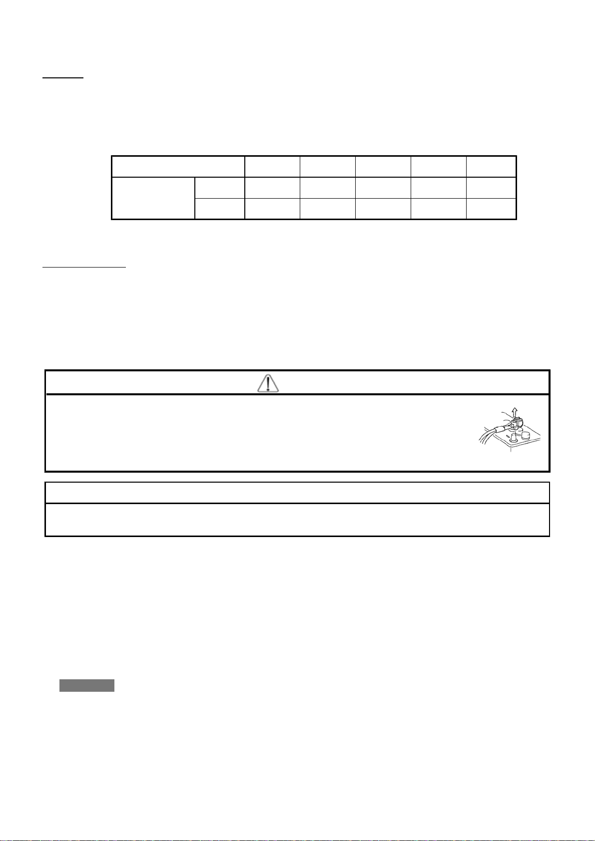
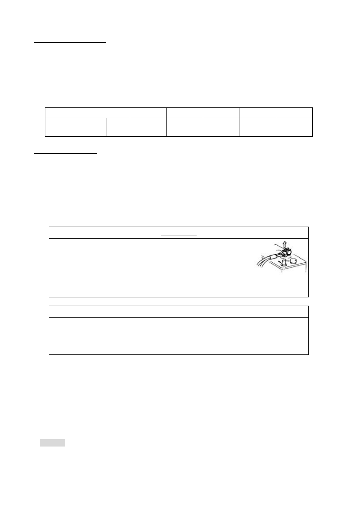
Disconnect the negative terminal of the battery before beginning installation to
prevent electrical damage and/or shock.
NOTE
Work on the vehicle in a well-ventilated area since fuel may leak during installation.
For optimal performance, larger injectors and/or a fuel pressure regulator may be
necessary.
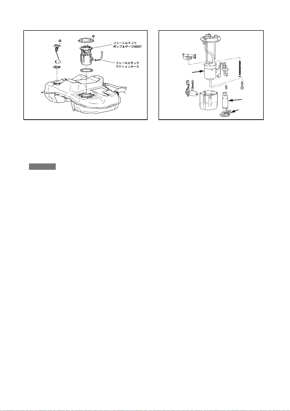
2. Removal of Factory Parts
Use this instruction manual and the manufacturer’s service manual as a reference.
(1) Remove the factory parts necessary to replace the fuel pump referring to the factory service
manual.
(2) Disconnect the wiring coupler on top of the fuel pump. Unlock the retainer and disconnect
the fuel hose. Make sure no foreign objects get inside the hose.
NOTE
・ Take all measures to prevent fuel from leaking.

-3-
(3) Remove the necessary nuts and remove the fuel pump assembly with gauge from the fuel tank.
Disconnect the suction hose from the pump and gauge assembly. Catch the remaining fuel
from the fuel pump with a container. (Diagram 2-1)
(4) Disassemble the fuel pump assembly and remove the factory fuel pump. The removed factory
gauge, wires, fuel filter, etc will be reused later. (Diagram 2-2)
3. Installing the Fuel Pump
(1) Install the removed spacer and O-Ring to the fuel pump’s outlet. Install the filter to the fuel
pump’s suction inlet, and push the filter on until properly seated. Install the fuel pump
assembly to the pump case.
NOTE
・ Apply silicone grease to the O-ring.
(2) Assemble the fuel pump using the opposite of the removal procedure. Connect the coupler to
the fuel pump. Make sure the gauge moves smoothly. (Diagram 2-2)
(3) Install the fuel pump assembly to the fuel tank after making sure the installing surface is clean.
When installing the fuel pump assembly, the pump, gasket and upper plate’s notch and tab must
be aligned. Tighten the nuts diagonally in steps.
(4) Connect the fuel hose and push the retainer down until it locks. Connect the wiring coupler.
(5) Reinstall all removed factory parts after confirming the items listed below.
4. Confirm After Installation
(1) Make sure all fuel routing is correct.
(2) Reconnect the negative cable to the battery.
(3) Turn on the ignition to build fuel pressure and to make sure fuel is not leaking.
(4) If fuel is not leaking, start the engine. Make sure fuel is not leaking once the engine is running.
(5) Re-tuning the engine is required since the fuel volume has changed.
D2-1
Fuel Pump &
Gauge
D2-2
Suction Hose Pump Case
Pump
Filter
Table of contents
Other HKS Automobile Accessories manuals

HKS
HKS Power Editor User manual

HKS
HKS HIPERMAX R User manual

HKS
HKS 80310-AF003 User manual

HKS
HKS 70020-AT115 User manual

HKS
HKS HIPERMAX R User manual

HKS
HKS HIPERMAX G+ LIFT UP User manual

HKS
HKS 15004-AT013 User manual

HKS
HKS 14005-AZ001 User manual

HKS
HKS 70019-AF011 User manual

HKS
HKS 71008-KF006B User manual