manuals.online logo
Brands
  1. Home
  2. •
  3. Brands
  4. •
  5. Hobby-Lobby
  6. •
  7. Toy
  8. •
  9. Hobby-Lobby albatros DVA User manual

Hobby-Lobby albatros DVA User manual

1
AlbatrosDVa
Wingspan: 52 in. (1325mm)
Length: 41 in. (1045mm)
Wing Area:723 in². (46.65dm²)
Flying Weight: 60 oz. (1.70kg)
Wing Loading 11.95 oz/sq. ft.
Centerof Gravity 2.6in. (66mm)back fromLEtop wing
2
Additional ItemsRequired
¨ 4-channelAircraft Radiow/ Receiver(minimum)
¨ 3cell Lipo battery2100-2500mAh
¨ (1)HitecHS-322 servo
¨ (2)eRC 8g servos
¨ (1)eRC 9g metalgearservo
¨ (2)12”servowireextensions
¨ eRC Brushless 45 ampESCw/SBEC
¨ eRC Brushless BL25 Motor
¨ APC12x6EPropeller
¨ 5-minuteEpoxyGlue
¨ ThinCAGlue
¨ Phillipsscrewdriver
¨ HexDrivers
¨ NeedleNosePliers
¨ HobbyKnife
¨ Soldering iron and electricalsolder
3
1.Install the full sizeservoforthe elevatorin
the fuselage. Placethe output shaft end of
the servotowardthe tail of the airplane.
2.Install the 9g metalgearservoforthe
rudderinthe fuselage. Placethe output
shaft end of the servotowardthe tail as
well.
3.Beforeinstalling the servoarms, slipthe
pushrodsintothe fuselage and attach“Z-
bend”end toservoarm.
4.Locatethe horizontalstabilizerand the
CAhinges.
5.Insert CAhingesintopre-cut slotsin
trailing edge of the horizontalstabilizer.
Insert the hinge 1/2wayintothe surface
and put apinthrough the hinge tokeep it
centered.
6.Slipthe elevatorontothe CAhinges,
leaveasmall gap between elevatorand
stabilizer.
7.Makesurethat the elevatorhasthe
mounting location forthe elevatorhornon
the right side of the center. The photo
showsthe stabilizerfromthe top view.
8.Check that the elevatoriscentered on the
stabilizerand that the gapsareeven
beforeyou applythe CAtothe hinges.
9.
4
10.If thereistoo muchwood showing on the
top of the stabilizer, iron on ascrap of the
matching covering fromthe sparecovering
provided.
11.Slide the horizontaltail intothe slot inthe
fuselage and center. DoNot Glue yet.
12.Locatethe verticalfinand rudderand
hinge togetherinthe samemannerasthe
horizontalstabilizerand elevator.
13.Insert the verticalfinand rudderintothe
slot on the top of the fuselage. Thereare
tabson the bottomof the verticalfinthat
must engage inslotson the horizontal
stabilizer.
14.When satisfied withthe fit CAthe joints
using thinCAand asmall tiptokeep
thingsneat.
15.Screwthe nylon controlhornstothe
elevatorand rudder. The elevatorhornis
on the bottomright of the elevatorand the
rudderison the left side of the rudder.
Usethe 6shorterscrewsthat looklikethe
phototothe right.
5
16.Single35”pieceof stranded wireisforthe
tail brace. The otherpairsof wireswill be
used laterforthe mainrigging of the
wings.
17.Locatethe tail bracepartsshowninphoto.
You will alsoneed the 35”wireand 2
crimptubes.
18.Install the Ushaped metaloverthe tail
skidand bolt inplacewithaswivelon
eachside.
19.Slide the wirethrough one of the crimp
tubesthen through the swiveland back
through the crimp. Lock inplaceby
crimping the tube withapairof pliers.
20.Thread the wirethrough the pre-drilled
holesinstabilizerand finand finishby
repeating the process on the othercrimp
21.Attachthe pushrodstothe rudderand
elevatorand adjust toneutralposition.
22.Removethe servohatchesfromthe
bottomof the upperwing.
23.Test fit the microservomaking surethat
the servoarmdoesnot bind on the
opening of the servohatch.
24.If the servoarmisnot centered inthe
opening, adjust bycutting the wood
mounting earsforproperfit.
6
25.Withservomounted on hatch, extend the
lengthof the servowirewitha12”
extension. Tape the connection sothat it
cannot be pulled loose.
26.Tiethe maleplug end of the extension to
the pull string located inthe wing.
27.Cut open the holeon the bottomof upper
wing nearthe cabane strut attachment.
28.Fishthe servoextension through the wing
and out the exit hole.
29.Repeat thisprocess forthe otheraileron.
30.Screweachhatchinplaceusing 4small
washerhead screws.
31.Install the CAhingesinthe leading edge
of the ailerons. Insert them1/2wayinthe
controlsurfaceand pinthe centerto
prevent the hinge being furtherinserted.
7
32.Check the hinge gap and keep it small.
Using the shaft of the pinasaguide isa
good idea.
33.When satisfied withthe fit of the aileron,
CAit inplacewithaquick shot of thinCA
glue. Flexthe controlsurfacedownand
add 3dropstoeachhinge then flex
aileron up and repeat the process.
34.Nipthe excess screwlengthoff withapair
of side cuttersoraDremelcut-off wheel.
35.Locatethe remaining 2nylon control
hornsand the longerscrewsand install in
the pre-drilled locationson eachaileron.
8
36.The photoat the right showsthe parts
needed toassemblethe landing gear. Not
showninthe photoarethe 3wheel
collars, you will need themaswell.
37.Slide one wheelontoaxeland then one of
the wheelcollars.
38.Next slipon one of the landing gearleg
attachment partsontothe axelwiththe
bendsleaning awayfromthe wheelas
shown.
39.Install the landing gearlegsontothe
attachment part.
40.Slide the landing gearspreaderbarwith
itsairfoil facing inthe direction of flight.
The longerleg isthe rearleg.
41.Slide on the otherlanding gearattachment
part followed byanotherwheelcollarand
tighten.
42.Install the remaining landing gearlegs.
9
43.Slipon the second wheeland the final
wheelcollarand tighten, makesurethat
the wheelsrotatefreely.
44.The assemblyshouldlooklikethe phototo
the right and isreadytoinstall intothe
slotsinthe fuselage.
45.Carefullyinstall the wireendsintothe slots
on the fuselage and slipthemfullyintothe
pockets.
46.Locatethe 4plyinsertsasshown.
47.Insert one plyspacerintoeachof the
slots. Donot applyglue, wewill add afew
dropsof CAwhen wehavethemall
complete.
10
48.You mayneed tousethe end of apieceof
plytoaidininserting the spacers,theyare
atight fit.
49.Oncefullyinserted applyafewdropsof
thinCAtoretainthe spacers.(See photo)
50.If you areusing the recommended eRC
BL25 motor, you will need toinstall the
lasercut plymounting disc tothe rearof
the motorinstead of the X-mount that
camewiththe motor.
51.The motorshaft must be shortened by
about 1/4" sothat the rearof the collet
adaptertouchesthe anodized motorcase.
52.If thisisnot done the spinnerwill havetoo
large agap behind it.
53.Slide the ESCintothe fuselage and screw
the motormount tothe firewall withthe
supplied allen head screws.
11
54.The installation shouldlooklikethe photo
tothe right.
55.Withthe dummymotorinstalled, the
batteryhatchinstallsand isheldinplace
withmagnets.
56.Install cabane strutson fuselage. Use
small machine screw, washerand nut.
57.Cabane shouldbe mounted tothe bottom
side of the supportsasshown.
58.Install the outboardstrutstothe bottomof
the upperwing. Mount themtothe outside
of the supports.
59.The installation shouldconsist of. Ascrew
through the strut and then the support.
Slipaswivelontothe screwthen awasher
followed bythe nut, snug inplace.
60.Photoshowsthe twoadditionalswivels
that areinstalled withsmall wood screws
tothe outboardunderside of the upper
wing. The location ispre-drilled.
12
61.Inaddition tothe cableyou will need this
hardware.
62.Machine screws, washersand nutsto
attachstrutstowingsand fuselage
63.Turnbuckles, cableconnectorsand cable
crimpstoattachcableand adjust cables.
64.Locatethe cablesand separateinto
groupsshown.
65.Two21”piecesat outboardwing tips
66.Bottomwing strut attachment front hole.
67.Fromthe outside of the strut insert screw
withswivelthrough strut an strut
attachment. Slide anotherswiveltothe
screwthen awasherand nut.
68.Withascrewand nut attachthe baseof 2
cableconnectorstothe top of the swivel.
69.Takeone of the 74”cablesand attacha
turnbuckleasshown.
70.Insert wireend through crimp, then
through eyeon turnbuckle, back through
crimpinoppositedirection, makealoop
and insertcablethrough crimpinthe same
direction again.
71.Snug up cableand crimpthe tube witha
pairof pliers.
72.Photoshowsassemblyuncrimped.
13
73.Install swivelon side offuselage nosewith
washerhead wood screw.
74.Unscrewthe turnbucklesothat you will
haveadjustment roomlater.
75.Start at the location showninphoto.
76.Slipone crimpon cableand thread cable
through swivelon noseand back through
crimp.
77.Next the cablegoesthrough the upper
rearswivelthen downtoloop at root of
lowerwing, finishing at upperfront strut.
78.Slipacrimpon cablebeforeinserting in
swivel, then back through the crimp. The
sameprocess asat the turnbuckle.
79.DO NOTTIGHTENAND CRIMPATTHIS
TIME
80.Repeat process on oppositewing.
81.Install one turnbuckletocableconnector
at outboardlowerstrut asshown.
82.Takeone of the 51”cablesand connect it
tothe turnbucklewithcrimpasbefore.
14
83.Thread cablethrough rearuppercabane
swivel, then through acablecrimp, then
the lowerwing root connectorand back
through the crimpbeforegoing tothe
uppercabane swiveland back tothe
turnbuckleat the baseof the outboard
strut.
84.Makesurethat you haveadjustment room
on the turnbuckle. Snug up the cables
beforecrimping.
85.Using the 21”cablescreatethe outboard
rigging starting at the upperfront swivel.
86.Three crimpswill be used. One at the
beginning, middleand end. No
turnbucklesareused here.
NOTE: When completeyou will have2
extraturnbucklesforsparepartsincaseof
loss.
87.When adjusting the rigging it isvery
important toadjust it evenlyand make
surenot towarpthe wing structure. It is
possibletowarpthe wingstothe extent
wherecontrolwiththe flight surfacesmay
be impossible.
VERYIMPORTANT: Oncewiresareadjusted
it isaverygood idea toput adab of glue
(UHU Pororsimilar) on eachof the nutsand
the turnbuckleadjustments.
88.Slippre-made machine gunsintoposition
on mounting tabs. Atouchof glue likeUhu
Porwill helpholdit inplace.
15
89.The spinnerisvacuformed and the
backplateisaluminum. Bothmust be
balanced aswell asthe 12x6APCE-prop.
90.Forbest resultsuseaprop balancer.
Aileron Control Throws
High Rate=5/8”Upand 1/2"Down
Low Rate=3/8”Upand 1/4"Down
ElevatorControl Throws
High Rate=1”Upand Down
Low Rate=3/4"Upand Down
RudderControl Throws
High Rate=1-1/8”EachDirection
Low Rate=7/8”EachDirection
CG
2.6”back fromtheleading
edgeoftheupperwing
Battery
3-cell 2100mAhLipo
WARNING –THISISNOTATOY!
Radiocontrolledmodelaircraft arecapableofinflicting seriousinjuryand/orpropertydamageifnot assembled, operated, and
maintainedin acompetent and safemanner. Ifyouarenot alreadyexperiencedwithradiocontrolledmodels, westronglysuggest
that youfind anexperiencedmodelertoassist you.
Warranty
Hobby-Lobbyguaranteesthiskit tobefree fromdefectsin bothmaterialand workmanship at thedateofpurchase. Thiswarranty
doesnot coveranycomponent partsdamagedbyuseormodification. Innoevent shall Hobby-Lobby’sliabilityexceedtheoriginal
cost ofthepurchasedkit.
16
HobbyLobbyInternational, Inc.
5614 FranklinPikeCircle
Brentwood, TN37027
1-866-WE-FLY-RC
(1-866-933-5972)
www.hobby-lobby.com

Other Hobby-Lobby Toy manuals

Hobby-Lobby Mini Telemaster Aileron Wing Kit User manual

Hobby-Lobby

Hobby-Lobby Mini Telemaster Aileron Wing Kit User manual

Hobby-Lobby Telemaster 40 Deluxe User manual

Hobby-Lobby

Hobby-Lobby Telemaster 40 Deluxe User manual

Hobby-Lobby Telemaster Electro V2 ARF User manual

Hobby-Lobby

Hobby-Lobby Telemaster Electro V2 ARF User manual

Hobby-Lobby eRC F-18E Super Hornet 90mm EDF User manual

Hobby-Lobby

Hobby-Lobby eRC F-18E Super Hornet 90mm EDF User manual

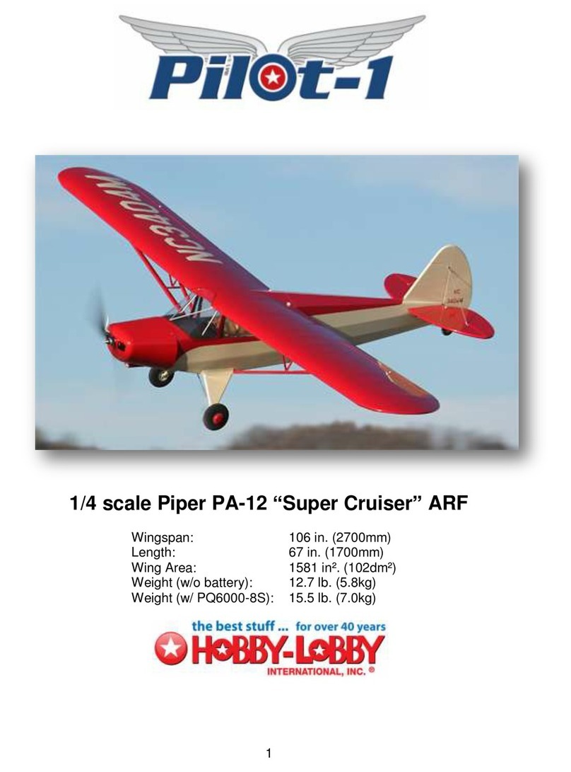
Hobby-Lobby Piper PA-12 Super Cruiser User manual

Hobby-Lobby

Hobby-Lobby Piper PA-12 Super Cruiser User manual

Hobby-Lobby HLI8601 F-86 Sabre Skyblazers User manual

Hobby-Lobby

Hobby-Lobby HLI8601 F-86 Sabre Skyblazers User manual

Hobby-Lobby ESM1100 User manual

Hobby-Lobby

Hobby-Lobby ESM1100 User manual

Hobby-Lobby Pilot-1 User manual

Hobby-Lobby

Hobby-Lobby Pilot-1 User manual

Hobby-Lobby Waco Biplane RTF User manual

Hobby-Lobby

Hobby-Lobby Waco Biplane RTF User manual

Hobby-Lobby Funster V2 User manual

Hobby-Lobby

Hobby-Lobby Funster V2 User manual

Hobby-Lobby Pilot-1 User manual

Hobby-Lobby

Hobby-Lobby Pilot-1 User manual

Hobby-Lobby F-35 Lightning II User manual

Hobby-Lobby

Hobby-Lobby F-35 Lightning II User manual

Hobby-Lobby Apache Princess User manual

Hobby-Lobby

Hobby-Lobby Apache Princess User manual

Hobby-Lobby SU-34 Fullback User manual

Hobby-Lobby

Hobby-Lobby SU-34 Fullback User manual

Hobby-Lobby Rebel 70 Sport Jet User manual
Hobby-Lobby

Hobby-Lobby Rebel 70 Sport Jet User manual

Popular Toy manuals by other brands

Hobby King Typhoon -EP manual

Hobby King

Hobby King Typhoon -EP manual

Step 2 Choo Choo Wagon 8160 quick start guide

Step 2

Step 2 Choo Choo Wagon 8160 quick start guide

V-tech Soft Songs Radio user manual

V-tech

V-tech Soft Songs Radio user manual

V-tech Pull & Play Phone user manual

V-tech

V-tech Pull & Play Phone user manual

LaserPegs 1270 Instructions for use

LaserPegs

LaserPegs 1270 Instructions for use

esky KING 3 operating instructions

esky

esky KING 3 operating instructions

De Agostini Model Space HUMMER H1 manual

De Agostini

De Agostini Model Space HUMMER H1 manual

KNEX Razor Instruction book

KNEX

KNEX Razor Instruction book

V-tech Mooove  n Count Cow user manual

V-tech

V-tech Mooove n Count Cow user manual

Air Hogs Jetscream instructions

Air Hogs

Air Hogs Jetscream instructions

V-tech Fix-It Buddies Toolbox Series Parents' guide

V-tech

V-tech Fix-It Buddies Toolbox Series Parents' guide

V-tech V.Smile: Up user manual

V-tech

V-tech V.Smile: Up user manual

Air Hogs Havoc Turbo Blast quick start guide

Air Hogs

Air Hogs Havoc Turbo Blast quick start guide

V-tech Toot-Toot Drivers Deluxe Track Set user manual

V-tech

V-tech Toot-Toot Drivers Deluxe Track Set user manual

V-tech Winnie the Pooh My First Words user manual

V-tech

V-tech Winnie the Pooh My First Words user manual

Smoby 330118 manual

Smoby

Smoby 330118 manual

WATT AGE 128295 operating instructions

WATT AGE

WATT AGE 128295 operating instructions

protech Racer380 instruction manual

protech

protech Racer380 instruction manual

manuals.online logo
manuals.online logoBrands
  • About & Mission
  • Contact us
  • Privacy Policy
  • Terms and Conditions

Copyright 2025 Manuals.Online. All Rights Reserved.