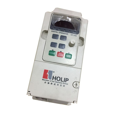
Holip HLP-C100 Series User manual

Operating Manual
2012-02
ZHEJIANG HOLIP ELECTRONIC TECHNOLOGY CO., LTD.
TEL: 0571-28891071 FAX: 0571-28891072
http: //www.holip.com

HLP-C100 Series Operating
Manual


HLP-C100 Series
HLP-C100 Series Operating Manual
Index
Introduction I
Chapter 1 Safety Precautions 1
1.1 Before power-up - 1 -
1.2 During the power-up - 2 -
1.3 During the operation - 3 -
1.4 After the power-off - 3 -
Chapter 2 Standards and Specifications - 4 -
2.1 Label Description - 4 -
2.2 Particular specifications - 5 -
2.3 Technical specifications - 5 -
Chapter 3 Installation and Wiring - 8 -
3.1 Checks before Installation - 8 -
3.2 Installation dimensions - 8 -
3.2.1 Dimensions of the Inverter - 8 -
3.2.2 Dimensions of the inverter - 9 -
3.3 Installation and Wiring - 9 -
3.3.1 Electrical Installation in General - 10 -
3.3.2 Fuse Specifications - 10 -
3.3.3 Installation and Direction - 11 -
3.3.4 Wiring terminal - 13 -
3.3.5 Wiring - 14 -
Chapter 4 Operation and Display Interface - 14 -
4.1 LCP Digital Operator - 14 -
4.2 Quick to set parameters - 14 -
4.2.1 Preset reference by LCP - 15 -
4.2.2 FWD/REV Status - 16 -
4.2.3 Data Read-outs - 17 -
4.2.4 View alarm record - 18 -
4.2.5 View state parameter - 20 -
4.2.6 LED Display - 21 -
Chapter 5 Quick Application Guide - 21 -
5.1 Parameter initialization - 21 -
5.2 Using LCP to control the drive [HAND] - 21 -
5.3 Using digital in terminals to control the drive [AUTO] - 21 -
5.4 Forward, Reverse and Jog - 21 -
5.5 Multi-speed - 22 -
Chapter 6 Parameter Overview - 23 -

HLP-C100 Series Operating Manual
HLP-C100 Series
Chapter 7 Parameter Description - 33 -
7.1 Parameter group 00: operation/display - 33 -
7.2 Parameter group 01: load and motor - 35 -
7.3 Parameter group 02: brakes - 39 -
7.4 Parameter group 03: reference/ramps - 41 -
7.5 Parameter group 04: limits/warnings - 51 -
7.6 Parameter group 05: digital input/output - 54 -
7.7 Parameter group 06: analog in/out - 55 -
7.8 Parameter group 07: controller - 59 -
7.9 Parameter group 08: comm. and options - 60 -
7.10 Parameter group 14: special functions - 62 -
7.11 Parameter group 15: drive information - 65 -
7.12 Parameter group 16: data readouts - 67 -
Chapter 8 Accessory Specification - 72 -
8.1 Braking resistor - 72 -
8.2 LCP Mounting Kit - 72 -
8.2.1 External LCP Communication Cable - 72 -
8.2.2 Mounting steps
Chapter 9 EMC - 73 -
9.1 EMC–Correct Installation - 73 -
9.2 RFI Switch - 73 -
Chapter 10 Warnings/Alarms and Fault Handling - 74 -
10.1 Fault list - 74 -
10.2 Fault indication and trouble shooting - 76 -
Chapter 11 Maintenance - 78 -
11.1 Note - 78 -
11.2 Storage and transport - 78 -
Chapter 12 Communication protocol - 79 -
12.1 Format specification - 79 -
12.2 Coil addressing - 79 -
12.3 Read coil status - 81 -
12.4 Read holding registers - 82 -
12.4 Force single coil - 82 -
12.5 Preset single register - 83 -
12.6 Force multiple coils - 84 -
12.7 Preset multiple regs - 85-
12.8 Read/write array - 85 -
12.9 Exception code - 87 -

HLP-C100 Series
HLP-C100 Series Operating Manual - 1-
Caution
●Check to be sure that the voltage of the main circuit AC power
supply matches the input voltage of the inverter.
●Install the inverter in a safe location, avoiding high temperature,
direct sunlight, humid air or water.
●The inverter can only be used at the places accredited by our
company. Any unauthorized working environment may have the
risks of fire, gas explosion, electric shock and other incidents.
●If more than one drive installed on the same control cabinet, make
additional cooling fan, so that the inside temperature is lower than
40℃ in order to prevent overheating or fire occurs.
●It will affect the service life of the inverter if a contactor is
installed on the input side to control the start and stop. Generally
it is required to control it through terminal commands. Special
attention should be paid to its use in the case of the start and stop
more frequently places.
●Do not install any switch component like circuit breaker or
contactor at the output of the inverter. If any of such components
must be installed due process and other needs, it must be ensured
that the inverter has no output when the switch acts. In addition,
it is forbidden to install any capacitor for improvement of power
factor or any varistor against thunder at the output. Otherwise
it will cause malfunctions, tripping protection and damages of
components of the inverter.
●Please use an independent power supply for the inverter. Do avoid
using the common power supply with an electrical welder and
other equipment with strong disturbance. Otherwise it will cause
the drive to protect or even damage the drive.
●Do not make any high voltage test with any component inside the
inverter. These semi-conductor parts are subject to the damage of
Chapter 1 Safety Precautions
1.1 Bef ore power-up
Caution Indicates misuse may damage the inverter or
mechanical system .
Danger Misuse may result in casualty.

HLP-C100 Series Operating Manual
HLP-C100 Series
- 2-
Danger
●Be sure to turn off the power supply before wiring.
●Mount the drive in the metal and other non-combustible materials
to avoid the risk of fire.
●Don’t install the drive in a space with explosive gas, otherwise,
they lead to explosion.
●R, S, T terminals are power input terminals, never mixed with
U.V.W terminals. Be sure that the wiring of the main circuit is
correct. Otherwise it will cause damages of the inverter when the
power is applied to it.
●The terminal of must be grounded separately and never
connected to N-line. Otherwise it will easily cause the protection
or errors of the inverter.
●Do not dissemble or modify any internal connecting cord, wiring
or component of the inverter by yourself.
●Never remodel it or exchange control boards and components by
yourself. It may expose you to an electrical shock or explosion,
etc.
●Keep the inverter from the reach of children or persons not
concerned.
Danger
●Do not plug the connectors of the inverter during the power up
to avoid any surge into the main control board due to plugging,
which might cause the damage of the inverter.
1.2 During the power-up
high voltage.
●The IC board of the inverter are susceptible to the effect and
damage of static electricity. Don’t touch the main circuit board.
●Installation, commissioning and maintenance must be performed
by qualified professional personnel.
●It should be handled with the base to avoid the dropping of the
inverter, which may possibly cause the injuries to people and the
damages to the inverter.

HLP-C100 Series
HLP-C100 Series Operating Manual - 3-
Danger
●Never connect or disconnect the motor set while the inverter is in
running. Otherwise it will cause over-current trip and even burn
up the main circuit of the inverter.
●Never remove the front cover of the inverter while the inverter is
powered up to avoid any injury of electric shock.
●Do not come close to the machine when the Reset Function is
used to avoid anything unexpected. The motor may automatically
recover from fault.
Caution
●Do not measure the signals on circuit boards while the inverter is
running to avoid danger.
●The drive has been optimized before sold. Please make proper
adjustments according to the desired functions.
●Do consider the vibration, noise and the speed limit of the motor
bearings and the mechanical devices.
1. 3 Dur i ng t he operat ion
Caution
●Even in the case of the main power, the other voltage inputs and
the share load (linkage of DC intermediate circuit) all have been
disconnected from the mains; the internal of the drive may still
have residual energy. Before touching any potentially live parts
of the inverter, please wait at least 4 minutes. Otherwise, it may
expose you to a risk of electrical shock.
1.4 Af ter the power-of f

HLP-C100 Series Operating Manual
HLP-C100 Series
- 4-
Chapter 2 Standards and Specifications
2.1 Label Description
Significance of the type code:
1-8 HLP-C100 Indicate Product Series
9-12 0D37 Indicate 0.37KW
13-14 21 Indicate 1-Phase AC 220V
23 Indicate 3-Phase AC 220V
43 Indicate 3-Phase AC 380V
15-17 P20 IP rating is 20
18 X Without AC choke
A With AC choke
19 X Without Brake unit
B With Brake unit
20 X Without DC choke
B With DC choke
21 1 Control panel with LED display and potentiometer
22 C With coating on PCB
23 X Reserved
24 0 Domestic sale
1 Overseas sale
25 A Without RS485
B With RS485
26-27 XX Reserved
28-31 VXXX Indicate sof tware version number, such as
V235 means the version number is 2.35 .

HLP-C100 Series
HLP-C100 Series Operating Manual - 5-
2.2 Particular Specifications
2.3 Technical Specifications
Model Input voltage
Input
current/
A
Output
current/
A
Rated
power/
KW
Suitable
motor/
KW
Net
weight/
KG
HLP-C1000D3721 1×200-240V50/60H Z
6.1 2.2 0.37 0.37 0.84
HLP-C1000D7521 1×200-240V50/60HZ
11.6 4.2 0.75 0.75 0.84
HLP-C10001D521 1×200-240V50/60HZ
18 .7 6 . 8 1. 5 1. 5 0 .8 4
HLP-C1000D3723 3×200-240V50/60HZ
3.5 2.2 0.37 0.37 0.84
HLP-C1000D7523 3×200-240V50/60HZ
6.7 4.2 0.75 0.75 0.84
HLP-C10001D523 3×200-240V50/60HZ
10.9 6.8 1.5 1.5 0.8 4
HLP-C1000D7543 3×38 0 - 4 4 0 V50 / 6 0 H Z
3.5 2.2 0.75 0.75 0.84
3×4 4 0 - 4 8 0 V50 / 6 0 H Z
3.0 2.1
HLP-C10001D543 3×38 0 - 4 4 0 V50 / 6 0 H Z
5.9 3.7 1. 5 1. 5 0 .8 4
3×4 4 0 - 4 8 0 V50 / 6 0 H Z
5.1 3.4
HLP-C10002D243 3×38 0 - 4 4 0 V 50 / 6 0 H Z
8.5 5.3 2.2 2.2 0.84
3×4 4 0 - 4 8 0 V50 / 6 0 H Z
7.3 4.8
Item Specification
Power supply
Supply voltage single/three phase 220V ±20%;
three phase 380V ±20%;
Frequency 48-62Hz;
Max. imbalance 3%;
Motor output
Out put voltage three phase 0-100% of supply voltage;
Output
frequency 0-400Hz
Main control
functions
Control mode V/F
Start torque 0.5Hz 150%;
Overload capacity 150% rated output current (60s)
PWM switch
frequency 2K-16KHz
Speed setting
resolution
Digital: 0.001Hz; a nalog y: 0.5‰ of t he
max. operating f requency ;
Control
command source LCP , digital terminal, local bus;
Frequency setting
source LCP , analog, local bus;
Ramp control Selectable 8-speed steps;

HLP-C100 Series Operating Manual
HLP-C100 Series
- 6-
Item Specification
Basic Functions
Automatic Voltage Regulation; V/F Control, DC Brake;
Speed Limit; Current Limit; Reset Function; Timer; PI
Controller.
Application
Functions
Speed Open-loop Control; Process Closed-loop Control;
Jogging ; Multi-speed Control via Digital input; Deferent
speed with deferent ramp; Mechanical Braking; Catch up /
Slow down; Relative Scaling Reference; Recover user settings
by a key etc.
Protection
Functions
Missing Motor Phase Protection; Low-voltage Protection;
Over-voltage Protection; Over-current Protection; Output
Phase Loss Protection; Output Short Circuit Protection;
Output Grounding Fault Protection; Motor Thermal
Protection; CPU Fault; EEPROM Faults; But ton f reeze;
Duplicate Fails; LCP Invalid; LCP Incompatible; Parameter
Read-only; Reference Out of Range; Invalid While Running;
Password Error etc.
Control
Te r m i n a ls
Digital input Number 5 digital inputs.
Scanning time 1ms;
Analog input
Number of input
1 a n alog i n p u ts( V I ),
both can receive
voltage or current
signals.
Input accuracy Max.error: 0.5% of
fullscale
Resolution 11b i t;
Scanning time 1ms;
Digital output Relay output 1 rela y ou t puts ( FA-
FB-FC) ;
Scanning time 1ms;
Power supply +10 V 10 V D C p o w e r
supply;
RS485 serial
communication
Te r m i n a l n u m be r 1, R S+ ( T X+, R X+),
RS-(TX-, RX-);
Ground for
RS485 COM;

HLP-C100 Series
HLP-C100 Series Operating Manual - 7-
Item Specification
Display
8 segments, 5
numeric displays
Display f requency, war nings, status and
so on;
Indicator Light FWD
、 REV
、 HZ
、 A
、 R/MIN
display various status of the inverter;
Data read-outs
Frequency setting, output f requency,
feedback value, output current, DC link
voltage, output voltage, output power,
input terminals state, output terminals
state, analogue input, 1-10 f ault records
and accumulated working time etc.;
Accessory
Remote
mounting kit
Available when the control panel for
external use;
Copy card Copy parameters f rom one inverter to
another ;
Environment
Enclosure IP20;
Ambient
temperature -10℃-40
℃;
Hu mid it y 5%-85% (95% wit hout cond ensa tion) ;
Vibration test 1.14g;
Max. altitude
above sea level
1000m, derating use when more than
1000 meters;
Motor cable
length
Shield cable: 5 meters, unshield cable: 50
meters;
Attention: Inverter under special environment (derating) :
●Derating for ambient temperature: If the f requency converter is
operated over 40
℃ambient temperature, the continuous output current
should be decreased. The f requency converter has been designed
for operation at max 50
℃ambient temperation with one motor size
smaller than normal. Continuous operation at f ull load at 50
℃ambient
temperation will reduce the lifetime of the frequency converter.
●Derating for low air pressure: The cooling capability of air is decreased
at low air pressure. Below 1000m altitude no de-rating is necessary but
above 1000m the ambient temperature or the maximum output current
should be decreased. Dcrease the output by 1% per 100m altitude above
1000m or reduce the max. ambient temperature by 1 degree per 200m.

HLP-C100 Series Operating Manual
HLP-C100 Series
- 8-
Chapter 3 Installation and wiring
3.1 Check s bef ore Instal lation
The inverter has been strictly and well packed before sold. In
consideration of various factors during the transportation special attention
should be paid to the following points before installation. If there is anything
abnormal please notif y the dealer or the relevant people of our company.
●Check if the inverter has got any damage or deformation during the
transportation and handling;
●Check if there is one piece of HLP-C100 series inverter and one copy of
the quick guide available when unpacking it;
●Check the information on the label to see if the specifications meet your
order (Operating voltage and KW value);
●Check if there is a certificate of qualification and a warranty card.
3.2 Installation Dimensions
3.2.1 Dimensions of LCP
59.5
21.7
57.1
12.8
13.3
92.6
89.2
Dimensions of the LCP are shown below(unit:mm):

HLP-C100 Series
HLP-C100 Series Operating Manual - 9-
3.2.2 Dimensions of the inverter
3.3 Installation and Wiring
3.3.1 Electrical Installation in General
Power(kW) A B C D E F
1×200-240V3×200-240V3×380-480Vmmmmmmmmmmmm
0.37-1.5 0.37-1.5 0.75-2.2 74 85 130 140 127 Ф5
Caution
●All cabling must comply with national and local regulations on
cable cross-sections and ambient temperature. Copper conductors
required, and ambient temperature(60-75℃) recommended.
Details of terminal tightening torques :
Power(KW)and Voltage
levels Tor q ue( Nm)
1×200-
240V
3×2 0 0 -
240V
3×380 -
480V Line Motor DC connection/
Brake
Control
terminals Relay
0.37-1.5 0.37-1.5 0.75-2.2 1.4 0.8 0.8 0.15-0.4 0.4

HLP-C100 Series Operating Manual
HLP-C100 Series
- 10 -
3.3.3 Installation and Direction
Note: Install the unit and make sure that it is f ree f rom high moisture、 high
temperature
、 heavy dust
、 metal f ragments and high oil mist.
3.3.2 Fuse Specifications
Model Fuse size (Rated current/A)
HLP-C1000D3721 10
HLP-C1000D7521 25
HLP-C10001D521 32
HLP-C1000D3723 10
HLP-C1000D7523 16
HLP-C10001D523 25
HLP-C1000D7543 10
HLP-C10001D543 10
HLP-C10002D243 16

HLP-C100 Series
HLP-C100 Series Operating Manual - 11 -
3.3.4 Wiring terminal
3.3.4.1 Main Circuit Terminals
Description of main circuit terminals:
Symbol Function
R
、 S
、 T
Power input:
220V class:1- phase 200-240V50/60Hz
3- phase 200-240V50/60Hz
380V class: 3- phase 380-480V50/60Hz
Single phase con nected to R、 T
U
、 V
、 W Power output, connect to the motor
-BR、 +BR Connect the brake resistor, make sure to set C02.10
、
C02.11 et c.
PE Ground terminal

HLP-C100 Series Operating Manual
HLP-C100 Series
- 12 -
Note: Only the machine with RS485 (type code number 25 is B) has RS+ RS-
and COM;
3.3.4.2 I/O Control Terminals
Description of I/O control terminals:
Symbol Description Specification
Relay output
(FA-FB-FC) Relay output
1
、 Resistive load: 250VAC 3A/30VDC 3A;
2
、 Ind uct ive load: 250VAC 0.2A /24VDC 0.1A
(cosφ=0.4) ;
3
、 FA FB normally closed, FB FC normally
open;
Digital input
(FOR
、 REV
、
DI1
、 DI2、 DI3)
Digital control
terminals
1
、 Logic:
>DC19V logic ‘0’;
<DC14V logic ‘1’;
2
、 Volt age: DC 0-24V;
GND Digital or
Analog ground Isolated f rom internal COM;
+10 V 10 V p o w e r
supply
Max.load 25 mA, with over load and short
circuit protection f unctions;
Analog input
(VI)
Analog setting/
Feed back
Set by the related parameter, analog input
channel can be configurated to 0-20mA or
0-10V :
Volt age i n pu t:
1
、 Input impedance: about 10 KΩ;
2
、 Maximum withstand voltage is 20V,
duration of 2 seconds, the maximum reverse
voltage is -15V, duration of 2seconds.
Current input:
1
、 Input impedence≤500Ω;
2
、 Maximum withstand current is 29 mA
duration of 2 seconds.
RS+, RS- RS485
communication RS485 + and RS485- ;
COM Ground for
communication Isolated f rom internal GND;

HLP-C100 Series
HLP-C100 Series Operating Manual - 13 -
3.3.5 Wiring
Basic Con nect ion Diag ram of HLP-C100 series inver ter:
Precautions for the main circuit wiring:
●While wiring the sizes and specifications of wires should be selected and
the wiring should be executed according to the electrical engineering
regulations to ensure the safety.
●It is better to use shielded wire or wire conduit for power cord and
ground the shielded layer or two ends of wire conduit.
●Be sure to install a circuit Breaker between the power supply and the
input terminals (R.S.T). (If using RCD, please choose B type)
●Phase-shif ting capacitors, LC, RC noise f ilters etc, can never be
connected to the output terminals of the inverter.
●Please lower the inverter switching f requency when there is a longer
distance between the inverter and the motor.
●Drive earth leakage current is greater more than 3.5 mA. According
to the requirments of IEC 61800-5-1 , must use the following ways to
enhance the protection of ground: minimum 10mm2cross sectional area
of copper, or additional PE line, its cross sectional area and the main
power cable should be the same, must be separate grounded.
●Make sure reliable ground of the inverter in accordance with IEC 61800-
5-1.
●Please refer to 9.2 for the use of RFI SWITCH.

HLP-C100 Series Operating Manual
HLP-C100 Series
- 14 -
Chapter 4 Operation and Display Interface
4.1 LCP Digital Operator
4.2 Quick to set parameters
Screen display
Status indicator
Menu key
Hand key
Shift key
Auto key
Off Reset key
Incremental
potentiometer
4.2.1 Preset reference by LCP
Example: Set a reference to10.25 That is C03.10 [0] =20.5:
Key-press LCP Display Action Description
C00.04 Press key to display the first basic
C00.03
C03.00 Tu r n clockwise to select parameter
group C03
C03.00 Press key to shif t to f ractional part
C03.10 Tu r n clockwise to select parameter
C03.10
[0] Press to show the first option of C03.10

HLP-C100 Series
HLP-C100 Series Operating Manual - 15 -
Key-press LCP Display Action Description
0000 Press to show the value of the first
option of parameter C03.10
000.5 Tu r n clockwise to change the
fractional part to5
000.5 Press key to shif t to integral part
020.5 Tu r n clockwise to change the integral
part to 20
END Press to accept the change and save it
as 20.5
4.2.2 FWD/REV Status
Confirm the direction of the motor according to the set value, as shown in
the following table:
Reference Running status Indicator Display
≥ 0STOP
< 0STOP
≥ 0FWD
≥ 0REV
Table of contents
Other Holip Inverter manuals
Popular Inverter manuals by other brands

V-TAC
V-TAC VT-66036103 instruction manual

Electriq Power
Electriq Power PowerPod 2 Quick user guide

Trace Engineering
Trace Engineering LEGEND II manual

SunSynk
SunSynk LIFELYNK X SM3.6kWLL user manual

Mastervolt
Mastervolt MASS SINE 400 Series quick start guide

Shihlin electric
Shihlin electric SF Series Guide for Manual

IZZY POWER
IZZY POWER HT-S-300 manual

Mitsubishi Electric
Mitsubishi Electric FREQROL-B instruction manual

Grant
Grant AS 1.0 Installation & user's instructions

Omron
Omron SPINOGY 3G3MX2 quick start guide

Generac Power Systems
Generac Power Systems heavy duty geenrator 1654-0 owner's manual

Goalo Elite
Goalo Elite Sherpa ui reference guide