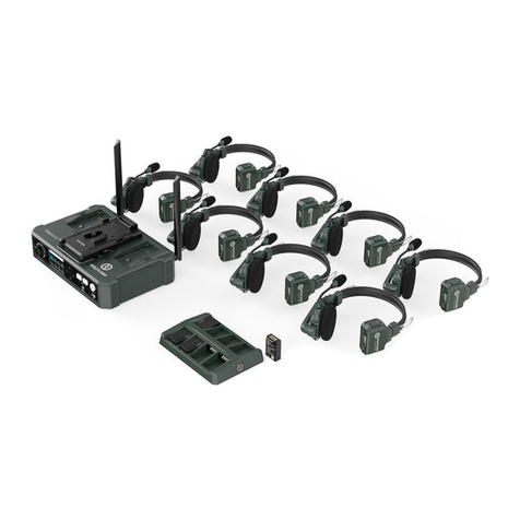
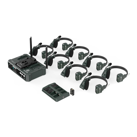
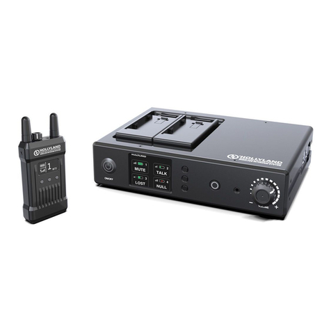
Hollyland SOLIDCOM M1 User manual

SOLIDCOM M1
User Manual
V1.0.0


1
Thank you for purchasing Hollyland Full-Duplex wireless intercom system. Please
read this instruction carefully before using the product. Wish you have a pleasant
experience.
Carrier-Grade Voice Quality, up to 450 Meters Line-of-Sight Usage Distance
1.9GHz Frequency, Support Frequency Configuration in Different Regions
Automatically Switching between External Omnidirectional Fiberglass Antenna
and In-Built Panel Antenna
Full-Duplex Wireless Communicating
The Station Supports up to 8 Beltpacks to Talk at the Same Time. Station, App and
Webserver Configuration Upgrade supported
Beltpack Supports Simultaneous Calls in 3 Groups
The Station Supports Cascading or Connecting with the 2/4 Wire Audio Systems
Station’s Power could be Supplied by POE Cascading or NP-F Type Batteries
In-Built Lithium Battery for the Beltpacks, Usage for over 6 hours
Portable Storage Charging Base, Easy to Carry
10 Levels Volume. Different Needs of Scenes Satisfied
FOREWORD
KEY FEATURES

2
PACKING LIST
⑤
① ② ③
④ ⑥
⑧⑦ ⑨
⑪⑩ ⑫

Station x1
①
Beltpack x8
②
Charging Base x1
③
x2
④
LEMO Single-Ear Headset
⑤
High Gain Omnidirectional Antenna
x8
POE Adapter x1
⑥
x1
⑦RJ45 to XLR Transferring Cable (5 meters)
* The exact quantity may vary on products configuration. Please take the actual quantity as standard.
PACKING LIST
x1
⑧
4Pin XLR Adapter
⑨
USB-Type-A to Type-C Transferring Cable
x1
Battery for Beltpacks x16
⑩
x1
⑪
User Guide
⑫x1
3
3/8 Installing Accessory

4
PRODUCT INTERFACES
Interface Definition: M G R L
Microphone Independence: 600Ω
Speaker Independence: 32Ω
MGR L
PIN1-PIN8
① ②
③
PIN1
PIN2
PIN3
PIN4
PIN8
PIN7
PIN6
PIN5
PIN1-PIN8
⑤④
PIN1PIN2
PIN3
①3.5mm Headset Interface
PIN1: GND
PIN2: GND
PIN3: SPK -
PIN4: SPK +
PIN5: MIC +
PIN6: MIC -
PIN7: NULL
PIN8: LED
②LEMO Headset Interface

PIN1: GND
PIN2: POWER
PIN3: AUDIO
④2-Wire Interface
Input Independence: 10KΩ
PIN1: NULL
PIN2: NULL
PIN3: AUDIO OUT+
PIN4: AUDIO IN+
PIN5: AUDIO IN-
PIN6: AUDIO OUT-
PIN7: GND
PIN8: GND
③4-Wire Interface
PRODUCT INTERFACES
PIN1: -POWER
PIN2: -POWER
PIN3: +POWER
PIN4: +POWER
PIN5: +POWER
PIN6: +POWER
PIN7: -POWER
PIN8: -POWER
⑤POE/PWR Interface
5

6
PRODUCT INTERFACES
A
①
②
③
④
⑤
⑥
⑦
⑧
⑨
⑩ ⑪ ⑫⑬ ⑭ ⑮

PRODUCT INTERFACES
Antenna Interface
①
Up Key
②
Left Key
③
④
Right Key
⑤
Menu/Confirm Key (Long Press to the Menu/ Short Press to Select)
STATION
Down Key
⑥
⑦
3/8 Screw Hole
⑧
Power Button
A
Interface for NP-F Type Battery
⑨
⑩
⑪
Power Supply Interface
USB Interface
⑫
3/8 Screw Hole
⑬
⑭
POE Interface
⑮
2-Wire Audio Input-Output Interface
4-Wire Audio Input-Output Interface (RJ45 Interface)
7

8
PRODUCT INTERFACES

Antenna
①
Mute/Talk Switch Key, Press Down for Talk, Up for Mute
②
Battery Compartment Switcher
③
⑤
Menu/ B Group Key (Long press to enter Menu/The beltpack is not grouped when
the indicator light is off. The beltpack is joined Group B but unable to talk or listen
when the Indicator light is white. The beltpack is able to talk and listen in Group B
when the Indicator light is orange)
⑥
Left Key/A Group Key (The beltpack is not grouped when the indicator light is off. The
beltpack is joined Group A but unable to talk or listen when the Indicator light is white.
The beltpack is able to talk and listen in Group A when the Indicator light is orange)
BELTPACK
Right Key/C Group Key (The beltpack is not grouped when the indicator light is off. The
beltpack is joined Group C but unable to talk or listen when the Indicator light is white.
The beltpack is able to talk and listen in Group C when the Indicator light is orange)
⑦
⑧
Volume- Button
⑨
Volume+ Button
B
Back Clip
⑩
⑪
⑫
Power Switcher
PRODUCT INTERFACES
USB Type-C Interface
④
Charging Contact
⑬
3.5mm Headset Interface
⑭
LEMO Headset Interface
9

①Current Battery Voltage of Station
②Current Status of Beltpack
④Current Battery Usage of Beltpack
⑤Current Signal Strength of Beltpack
⑥Low Battery Display of Beltpack
10
DISPLAY INTRODUCTION
ASTATION MAIN DISPLAY INTRODUCTION
A
TALK: The beltpack is able to talk while listening.
MUTE: The beltpack is able to listen but unable to talk.
LOST: The beltpack is disconnected from the station.
LINK: The beltpack is linking to the station.
③Beltpack Number
2
TALK
3 4
6 7 85
LOST
TALK TALK
TALKTALK TALK
Master 7.8 V
Ho l l y V iew
1
MUTE
①
②
③
④
⑤
⑥

DISPLAY INTRODUCTION
①Current Signal Strength
②Charging Notice
④Beltpack Number
⑤Current Status
BBELTPACK MAIN DISPLAY
B
TALK: Able to Talk while Listening
MUTE: Able to Listen but unable to Talk
LOST: Disconnected from the Station
LINK: Linking to the Station
③Current Battery Usage
① ② ③
④ ⑤
TALK
7
11

GUIDE
12

GUIDE
STATION MENU INTRODUCTION
Long press Menu/Confirm Key for 3 Seconds to enter the Menu, following is the menu
function's Introduction.
①Select “Network” to Switch WiFi on/off, See the WiFi Password
and IP Address.
2.1 If there's only one kit of devices, the station needs to be set as Master Device; When
two or more kits are cascaded, the station can be set as Master Device/ Slave Device.
2.2 When the station is set as Master Device, The beltpack number will automatically
switch to 1-8; When the station is set as Slave Device, The beltpack number will
automatically switch to 9-16.
2.3 This function can only be used when two kits of devices cascaded by Ethernet
interface. The Station needs to be set as Master Device when only one kit of devices used.
②Select “Master and Slave” to Set the Station as Master
Device/Slave Device.
3.1 Enter the Menu to adjust 4 Wire audio system input/output gain.
3.2 Switch sequence of line.
③Select “4 Wire” Entering 4 Wire Audio Settings.
④Select “Language” to Switch Language to Chinese or English.
5.1 One Group: To group all the beltpacks, 2 Wire and 4 Wire audio devices to Group A.
The indicator light of Group A Key on the beltpacks will shine
5.2 Two Groups: To group number 1-4 beltpacks, 2 Wire and 4 Wire audio devices to
Group A, number 5-8 beltpacks to Group B, The indicator light of corresponding groups on
the beltpacks will shine.
5.3 Customize: Able to group beltpacks, 2 Wire or 4 Wire audio devices though Direction
Keys and Confirm Key. After setting the corresponding indicator light of the beltpack will
shine;
5.4 Defaults: Able to group all beltpacks, 2 Wire and 4 Wire to Group A, After setting the
indicator light of Group A will shine.
⑤Select “Group” Entering Group Settings.
13

GUIDE
6.1 After connected to 2 Wire devices, set the corresponding wire length compensation
and terminal resistor of the station. Powe on the 2 Wire devices. Meanwhile the
microphone of 2 Wire devices needs to be turned off or disconnected to make sure there's
no other audio transmitting in the 2 Wire connection. Otherwise, the Auto Null will be
affected. Select “Auto Null”, the station will complete the Auto Null operation of 2 Wire
Devices;
6.2 Select “Cable Compen”, confirm the bus length of the same parallel 2 Wire Interface.
Select the corresponding compensation selection according to the bus length;
6.3 Select “Terminal Res”, confirm whether the 2 Wire Device connected by the 2 Wire
interface has terminal resistor. The terminal resistor needs to switch to Off if the 2 Wire
Device has terminal resistor. The terminal resistor needs to switch to On if the 2 Wire
Device doesn't have terminal resistor.
6.4 Select “Input Gain” to enter input gain adjust menu, Select the corresponding level to
increase or decrease the corresponding value of the input signal;
6.5 Select “Output Gain” to enter output gain adjust menu, Select the corresponding level
to increase or decrease the corresponding value of the output signal.
⑥Select “2 Wire” Entering 2 Wire Settings.
⑦Select “Reset” to Reset all the Adjusted Info of Station to Defaults.
⑧Select “Info” to Check the Information of the Station.
14

GUIDE
BELTPACK MENU INTRODUCTION
Long press Menu Key for 3 seconds to enter the menu, Following is the introduction of
each function.
①Connect the Beltpack to the Station by USB-A to TypeC Cable,
Select “Pair”, the Beltpack can Paired with Station.
SideTone off when it is at Level 0, The SideTone will Increase from Level 1 to 3.
②Select “SideTone” to set the SideTone Output Volume.
③Select “Language” to Switch Language to Chinese or English.
④Select “Reset” to Reset all the Adjusted Info of Beltpack to Defaults.
Select the usable number from 1 to 8 to confirm paring, Both the station and the beltpack's
screens will display “Pairing…”. Disconnect the beltpack from station when the screens
Display “Pairing Successful”.
⑤Select “Info” to Check the Information of the Beltpack.
⑥Select “Exit” Exit to the Main Menu.
15

GUIDE
SET THE STATION BY WEB SERVER
Power on the station. Connect POE or PWR Interface to the Ethernet interface of
computer by Ethernet Cable. Configure the network segment of the computer to be
consistent with the station, Then open the browser on the computer and enter the
following address (Check the corresponding address through the Network Menu of the
station).
Master Device: 192.168.218.10
Slave Device: 192.168.218.11
Log in and enter Web page (Default passcode:12345678) can upgrade the Station,
group the beltpacks and adjust the status of beltpacks.
SET THE STATION BY APP
Turn on the WiFi of station. Find the WiFi start with “HLD” on the phone and connect.
Open the Solidcom App to connect. (Turn the WiFi on and check the corresponding
Wifi name and password through the Network Menu of the station)
16

PRODUCT INSTALLATION
① ②
③
1. Install the antenna according to the picture.
2. Connect the power adapter, or install NP-F type battery.
3.Press the power button to power on.
①Station Installation
17

PRODUCT INSTALLATION
18
Table of contents
Other Hollyland Intercom System manuals
Hollyland
Hollyland Solidcom C1 Pro User manual

Hollyland
Hollyland Solidcom C1 Pro User manual

Hollyland
Hollyland MARS T1000 User manual

Hollyland
Hollyland MARS T1000 User manual

Hollyland
Hollyland SOLIDCOM C1 User manual

Hollyland
Hollyland Solidcom C1 HUB8S User manual

Hollyland
Hollyland Solidcom C1 Pro User manual

Hollyland
Hollyland HOLLYVIEW LARK 150 Quick start guide

Hollyland
Hollyland Solidcom C1 Pro User manual
Hollyland
Hollyland MARS T1000 Quick start guide