manuals.online logo
Brands
  1. Home
  2. •
  3. Brands
  4. •
  5. Hollywood Racks
  6. •
  7. Automobile Accessories
  8. •
  9. Hollywood Racks HR3000-E User manual

Hollywood Racks HR3000-E User manual

HOLLYWOOD RACKS Assembly guide for TRS (Tire Retention System) E-bike rack
•Model HR3000-E (1 ¼” – 2” hitches) 2 BIKE CAPACITY, MINIMUM CLASS II HITCH REQUIRED
•Model HR3500-E (2” hitches only) 2 BIKE CAPACITY, MINIMUM CLASS II HITCH REQUIRED
Weight Limit 65 lbs/29.5 kg per bike
Maximum Bike Tire Width: 4.5”
Not to be used on any trailer, fifth wheel or towed vehicle
Not for use with gas powered bikes or motorcycles
HOLLYWOODRACKS.COM
IF YOU HAVE PURCHASED THE TRS E-BIKE ADAPTER IN A
SEPARATE BOX AS AN UPGRADE KIT, PLEASE REFER TO THE
ATTACHED ADDITIONAL INSTRUCTION SHEET BEFORE ASSEMBLY.
2
Fig. 1
ID DESCRIPTION QTY
D OUTSIDE BIKE TIRE HOOK 1
E INSIDE BIKE TIRE HOOK 1
F TIRE CAGE 2
G WHEEL TRAY (HALF) 4
H UPPER PLATE 2
J1, J2 TIRE CAGE CAPS 4
K RATCHET STRAP 4
L INNER SUPPORT TUBE 1
M OUTER SUPPORT TUBE 1
N CENTER SUPPORT TUBE 1
ID DESCRIPTION QTY
A MAIN FRAME 1
B 2” HITCH TUBE (INCLUDED WITH
MODEL HR3500-E) 1
B1 LOCKING HITCH PIN & CABLE
(INCLUDED WITH HR3500-E) 1
C 1 ¼ -2” HITCH TUBE (INCLUDED
WITH MODEL HR3000-E) 1
C1 LOCKING HITCH PIN & CABLE
(INCLUDED WITH HR3000-E) 1
HARDWARE:
ID DESCRIPTION QTY
a-a carriage bolt, 5/16-18 x 2” 4
b-b lock nut, 5/16-18 10
c-c carriage bolt, 5/16-18 x 3.5” 4
d-d multi-wrench 1
e-e steel washer, 8.5mm ID 12
f-f 6mm internal tooth lock washer 2
g-g nylon washer, 8.5mm ID 4
h-h socket screw, M6x40mm 4
i-i washer, 6.5mm ID 4
j-j nylock nut, M6 4
k-k Phillips head screw, M6 2
l-l 4mm Allen key, HR3000-E only 1
m-m socket head bolt, ½-13 x 85mm 1
n-n nylock nut, ½-13 1
o-o bushing, ½” ID 1
p-p washer, 13.5mm ID 1
q-q 8mm Allen key 1
r-r 5mm Allen Key 1
s-s hex bolt, 5/16-18 x 1.5” 1
t-t hex bolt, 5/16-18 x 3.5”1
Hollywood Racks stickers 2
3
Step 1: Assemble main frame to
hitch tube.
Per Fig. 5, prepare the
components on a flat table or
work surface.
Per Fig. 6, locate the Spring Pins
and holes in the folding bracket
Fig. 6 & 7: Retract the rear spring pin and
insert the hitch tube into the folding
bracket. Align the small hole of the
folding bracket with the small hole of the
square tube. After inserting, the rear
spring pin will drop into the large hole in
the square tube.
Fig. 7 & 8
Install bushing o-o onto bolt
m-m and insert bolt & washer
though holes A1 so the end of
the bolt is protruding out of the
bracket.
Install washer p-p and nut n-n
onto bolt end using hex key q-q
and wrench d-d (or adjustable,
¾” or 19mm). Tighten securely.
They may have to be re-
tightened after the rack has
been installed into the trailer
hitch.
Note: it will be easier to do this part of the assembly on a flat surface or work table.
4
Fig. 8: Tighten bolt m-m and nut n-n until end of bolt is protruding through the end of nut. Tighten securely.
As this will require a fair amount of torque, insert Allen key q-q into the bolt so the handle is resting against
the tube. Now use wrench d-d or equivalent to tighten nut n-n.
Fig. 8
Fig. 5
Fig. 6
Fig. 7
Step 2: Install rack into hitch
Step 2A: For model HR3500 (2” “no-wobble system” version, locking hitch pin included):
Install Hitch Tube (B) into vehicle’s trailer hitch Fig. 10:Slide the rack in the folded-up position into the
trailer hitch until it stops. Fig 10: Remove locking head from hitch pin B1 and insert pin through the hole in
the trailer hitch and hitch tube until it passes through the opposite side. Tighten the front lever until good
and snug. If you intend on using the rack after assembly, then install the locking head onto the end of the
hitch pin, otherwise it is not required to complete the assembly. Front lever position after tightening
should always be pointed to the side to avoid damage when going up or down steep driveways.
Step 2B: For model HR3000 (1 ¼”-2” threaded hitch pin version, locking hitch pin included):
Install Hitch Tube (c) into vehicle’s trailer hitch Per Fig. 11 &12, insert the receiver tube into the hitch and
align the holes. Thread and tighten the bolt securely through the hitch and receiver tube using a wrench
(adjustable, ¾” or 19mm) then install the hitch pin lock. The rack should now be solidly mounted to your hitch.
Use with 1 ¼” hitches:
If the rack is to be used on a 1 ¼” hitch, remove the aluminum spacer
block from the receiver tube with the included 4mm Allen key l-l.
Fig. 10
Fig. 11
5
Fig. 9
Fig. 12
Fig. 13
Step 4: Assemble tire cages to main frame (This step easier when the rack is in it’s “in-use” position)
Per Fig. 14: Locate the main frame’s square bracket and prepare tire cage Fand hardware. Install Plastic
tire cage caps J1 and J2 onto tire cage F (if not already installed).
Per Fig. 16: Before assembly, check that the holes of J1 and J2 are aligned with the holes of tire cage F. If
not aligned, use the hex key or a thin screwdriver to make the alignment. Place the tire cage onto the
square bracket and align the holes. Insert the bolts through the tire cage so they protrude through the
square bracket. Install washers i-i and nuts j-j onto the bolts using 5mm hex key r-r and wrench d-d (or
small adjustable, 3/8” or 10mm). Tighten so that the tire cage has medium to strong resistance when
folding. Repeat for second tire cage.
Try rotating the tire cages forward. There should be medium to strong resistance.
Step 3: Fold-Up/Fold-Down
Fig. 12: From the rack’s
folded to “in use” position,
pull the rear spring pin out
and rotate the rack down
until the front spring pin
clicks into place.
To return the rack to its
folded position, pull the
front spring pin out and
rotate the rack up until the
rear spring pin clicks into
place.
Fig. 14
Fig. 15
6
Fig. 12
“in-use” position
“folded” position
Step 5: Install Tire Hooks
Per Fig. 17: Prepare the tire hooks, washers f-f and screws k-k (Phillips screwdriver required). Use Inside Tire
Hook Efor inner bike position (closest to car). Slide the Inside Tire Hook Edown over the outer ratchet arm.
Note the trigger faces the driver’s side of the vehicle. Hook will be centered over the rack’s inside bike tire
cage. Insert screw k-k into washer f-f. Install washer & screw into hole located at top of ratchet arms with
screwdriver.
Per Fig. 24: Slide the Outside Tire Hook Ddown over the inner ratchet arm. Note the trigger faces the
passenger’s side of the vehicle. Hook will be centered over the rack’s outer bike tire cage. Install washer &
screw into hole located at top of ratchet arms with screwdriver.
Fig. 16
Fig. 17
7
Step 6: Install Wheel Tray Straps
Slide the ratchet straps Kinto the
aluminum wheel trays. Be sure they
are facing in the same direction.
Fig. 18
Fig. 19
8
Step 7: Install wheel support tubes: Fig. 20-22:
Place large washer g-g on the round tube frame.
Then place the inside wheel support tube Lon top of
the washers, aligning the holes. The “long end” of the
support tube must be resting on top of the bracket as
shown in Fig. 21. Insert bolts c-c through the support
tube, washers and round frame tube. Install the
washer and nut onto the end of the bolt, and finger
tighten the nut. It will be fully tightened later.
Repeat for the outside wheel support tube M. Note
outside wheel support tube M has the U shaped
bracket to it’s bottom side.
Step 8: Install center support tube: Fig. 23-25
Step 9: Install wheel
trays: Fig 27: Slide the
aluminum wheel trays
onto the protruding
bolt-head. Note ratchet
straps should be on the
“far side” of the tray.
Repeat for the other
side, allowing the trays
to meet in the center of
the support tubes.
Fig. 27&28: Insert bolts
a-a through the holes in
plate H. Align the holes
of the tray with the
holes of the support
tube, and insert the
bolts with plate through
the wheel trays and
support tube. Install
washer e-e and nut b-b
and tighten securely.
Next, tighten the nuts
on bolts c-c securely.
9
Fig. 26
Fig. 29
Per Fig. 29, rotate the rack to its folded
position and double check that all
hardware has been installed correctly and
securely.
Fig. 28
Fig. 27
Step 10: Tilt-Down Function
Per Fig. 30 & 31: Lift up the rack and
remove the snapper pin. Pull out the front
spring pin and hold the main frame while it
tilts down into position. To return the rack
to its in-use or folded up position, lift the
main frame until the front spring pin clicks
into place. Lift rack and install the snapper
pin snapper pin.
Fig.31
Fig. 30
Step 11: Final adjustments
Per Fig. 32, Re-tighten bolt m-m and nut n-n until end of
bolt is clearly flush with end of nut. As this will require a
fair amount of torque, insert Allen key q-q into the bolt
so the handle is resting against the tube. Now use
wrench d-d or equivalent to tighten nut n-n.
10
Step 12: Loading and unloading bikes: (be sure front tire is fully inflated!)
1. Rack should be in the user position with tire cage(s) rotated forward and ready to use (Fig. 33).
2. Rotate ratchet post outwards until it stops, ratchet straps should be undone (Fig. 34).
3. Lift bike and place the front wheel firmly against the inside of the tire cage. (Fig 35)
4. Rotate ratchet post back towards the fork. The hook should be extended far enough up to clear the top of
the tire.
5. Pull down on the ratchet handle to firmly engage the tire just in front of the fork. (Fig. 36)
6. Secure ratchet straps firmly on both front and rear wheels. Ratchet straps should be located below the
axels or slightly closer to the center of the bike. (Fig. 37)
7. Repeat for second bike.
Step 13: Unloading the bikes: Undo the ratchet straps. Pull back on the bike to release tension on the tire
hook. Engage the trigger on the ratchet post housing and slide the hook up by the housing, not the rubber
coated tire hook. Rotate the post outwards the remove the bike. Repeat for the second bike. Rotate the tire
cage(s) forward to its folded position and fold the rack up against the rear of the car. (Fig. 38, 39, 40)
Fig. 32
m-m
IF CARRYING ELECTRIC BIKES, REMOVE THE BATTERY
BEFORE LOADING. MAXIMUM WEIGHT CAPACITY IS 65 LBS
(29.5 KG) PER BIKE. DO NOT OVERLOAD!
11
9-A
Fig. 33
Fig. 34
Fig. 35
Fig. 36
Fig. 37
Fig. 38
Fig. 39
DOUBLE CHECK BEFORE DRIVING THAT HOOKS ARE FIRMLY ENGAGED AGAINST TIRE AND RATCHET WHEEL
STRAPS ARE FIRMLY ATTACHED. DRIVE SLOWLY ON BUMPY OR DIRT ROADS. THIS PRODUCT IS NOT TO BE
USED ON ANY TRAILER, FIFTH WHEEL OR TOWED VEHICLE.
12
Fig. 40
Fig. 41
Fig. 42
Limited Lifetime Warranty (effective January 1, 2008):
Hollywood Racks will warrant its car racks and accessories during the time that an original retail purchaser owns the product
subject to the exclusions and limitations of this warranty. Hollywood Racks will remedy defects in materials and workmanship
by repairing or replacing (at its option) a defective part without charge for labor or parts. Hollywood Racks may elect (at its
option) to issue a refund equal to the purchase price paid for the product. This warranty does not cover problems caused by
normal wear and tear including (but not limited to) weather, scratches, dents, rust, accidents, unlawful vehicle operation,
misuse, abuse, neglect, theft, unauthorized modifications, or unauthorized repair. No warranty is given for defects resulting in
incorrect assembly, incorrect installation onto the vehicle, installation on a “no fit” vehicle, incorrect attachment of bicycles
onto the rack, or overloading of the rack’s weight restrictions. This warranty terminates if the original retail purchaser transfers
the product to any other person. If a product is believed to be defective, the original retail purchaser should contact either the
original retailer or Hollywood Racks directly at 800-747-4085 or at info@hollywoodracks.com Disclaimer of Liability: Repair or
replacement of a defective product or the issuance of a refund or credit (as determined by Hollywood Racks) is a purchaser’s
exclusive remedy under this warranty. Damage to a purchaser’s vehicle, cargo, bicycles and or to any other person is excluded.
This warranty is expressly made in lieu of any and all other express warranties, whether oral or written. Hollywood Racks shall
not be liable for any direct, indirect, consequential, incidental, special, punitive or any other damages in connection with the
purchase, use or handling of this product. Some states do not allow the exclusion or limitation of consequential or incidental
damages and the above limitation may not apply to you. This warranty gives you specific legal rights and you have other rights,
which vary from state to state.
Hollywood Racks
12812 South Spring Street Los Angeles, CA 90061 (800) 747-4085 (310) 516-8600 Fax (310) 516-8955
Customer Service: M-F 8:00 AM- 3:00 PM PST www.hollywoodracks.com info@hollywoodracks.com
Made in Taiwan TRS E-Rack V2.1 01/2019

This manual suits for next models

1

Other Hollywood Racks Automobile Accessories manuals
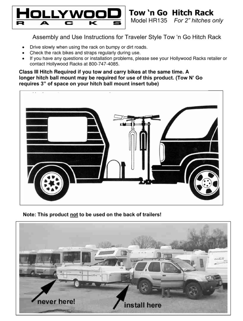
Hollywood Racks HR135 Quick setup guide

Hollywood Racks

Hollywood Racks HR135 Quick setup guide

Hollywood Racks 1 Instruction manual

Hollywood Racks

Hollywood Racks 1 Instruction manual

Hollywood Racks HR6000 Quick setup guide

Hollywood Racks

Hollywood Racks HR6000 Quick setup guide

Hollywood Racks Trike Adapter 2 Instruction manual

Hollywood Racks

Hollywood Racks Trike Adapter 2 Instruction manual

Hollywood Racks HR1200 User manual

Hollywood Racks

Hollywood Racks HR1200 User manual

Hollywood Racks HR150 User manual

Hollywood Racks

Hollywood Racks HR150 User manual

Hollywood Racks Sport Rider HR1475 User manual
Hollywood Racks

Hollywood Racks Sport Rider HR1475 User manual

Hollywood Racks Sportrider HR1500 Instruction manual

Hollywood Racks

Hollywood Racks Sportrider HR1500 Instruction manual

Hollywood Racks HR4000 User guide

Hollywood Racks

Hollywood Racks HR4000 User guide

Hollywood Racks F6 User manual

Hollywood Racks

Hollywood Racks F6 User manual

Hollywood Racks Road Runner 3 Series Instruction manual

Hollywood Racks

Hollywood Racks Road Runner 3 Series Instruction manual

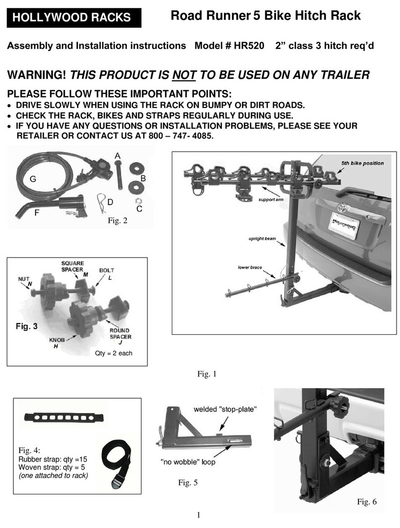
Hollywood Racks Road Runner 5 Bike Hitch Rack Instruction manual
Hollywood Racks

Hollywood Racks Road Runner 5 Bike Hitch Rack Instruction manual

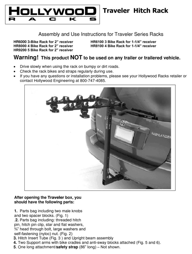
Hollywood Racks HR3000 User manual

Hollywood Racks

Hollywood Racks HR3000 User manual

Popular Automobile Accessories manuals by other brands

DEFA 422857 Fitting instructions

DEFA

DEFA 422857 Fitting instructions

Intermec CV41 Configuration guide

Intermec

Intermec CV41 Configuration guide

Keba KeContact P30 b Series Functions & Procedures

Keba

Keba KeContact P30 b Series Functions & Procedures

Vision Systems VS55020 user manual

Vision Systems

Vision Systems VS55020 user manual

CAMMUS SWH 2021 manual

CAMMUS

CAMMUS SWH 2021 manual

Truma Mover XT L operating instructions

Truma

Truma Mover XT L operating instructions

Volvo 30661683 Installation instructions, accessories

Volvo

Volvo 30661683 Installation instructions, accessories

Tuffy 182 installation instructions

Tuffy

Tuffy 182 installation instructions

Cruz 909-401 Assembly instructions

Cruz

Cruz 909-401 Assembly instructions

Front Runner SSDS105 manual

Front Runner

Front Runner SSDS105 manual

Cisbo Parking sensor user manual

Cisbo

Cisbo Parking sensor user manual

Fiamma 02093A05A Installation and usage instructions

Fiamma

Fiamma 02093A05A Installation and usage instructions

TUWA PRO BR47B installation guide

TUWA PRO

TUWA PRO BR47B installation guide

Kuda 043230 Installation instruction

Kuda

Kuda 043230 Installation instruction

P3 International MK5 installation guide

P3 International

P3 International MK5 installation guide

Calix group MVP 528 Assembly instructions

Calix group

Calix group MVP 528 Assembly instructions

AL-KO Power Mover operating instructions

AL-KO

AL-KO Power Mover operating instructions

Xforce ES-FRS16VMKSB-CBS quick start guide

Xforce

Xforce ES-FRS16VMKSB-CBS quick start guide

manuals.online logo
manuals.online logoBrands
  • About & Mission
  • Contact us
  • Privacy Policy
  • Terms and Conditions

Copyright 2025 Manuals.Online. All Rights Reserved.