6
© HOLMS INDUSTRI AB, ALL RIGHTS RESERVED 6/4/06
HOLMS INDUSTRI AB
MOTALA SWEDEN
SL
1. Set the sweeper height and tilt.
2. Let the sweeper rotate a short while against the ground.
3. Measure the clean-swept stripe, it shall normally be ca
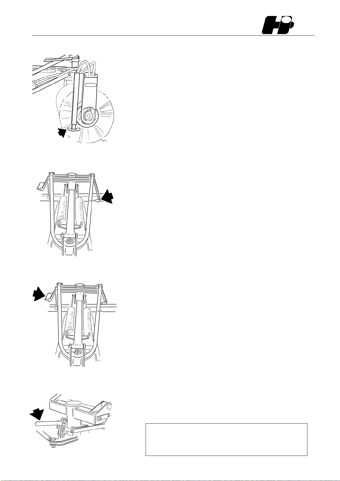
10 cm.
Warning!
Always lower the attachment so the springs are
relieved before making any adjustments.
Decrease the ground pressure by lowering the adjusting
grip.
Increase the ground pressure by raising the grip
(picture 7).
Sweeping
By sweeping the setting normally shall be as described in
“Sweeper setting, height and tilt”. The yellow markers on
the height- and tilting indicators shall be in line. In this
position the loader bracket is vertical to the ground. The
sweeper operates with even pressure over its whole width.
Attention! Do not use the loader height and tilting function
for ground pressure adjustment.
By requirement of harder ground pressure on any side of
the sweeper or if the sweeper is unevenly worn the adjust-
ment can be made by changing the tilt setting.
Bybackwardstiltingharderpressureisreachedontheside
of the sweeper which is angled towards the loader.
By forwards tilting harder pressure is reached on the side
of the sweeper which is angled from the loader.
Whenliftingthe sweeperfrom thegroundfortransport,use
tilting backwards to avoid leaf spring damage.
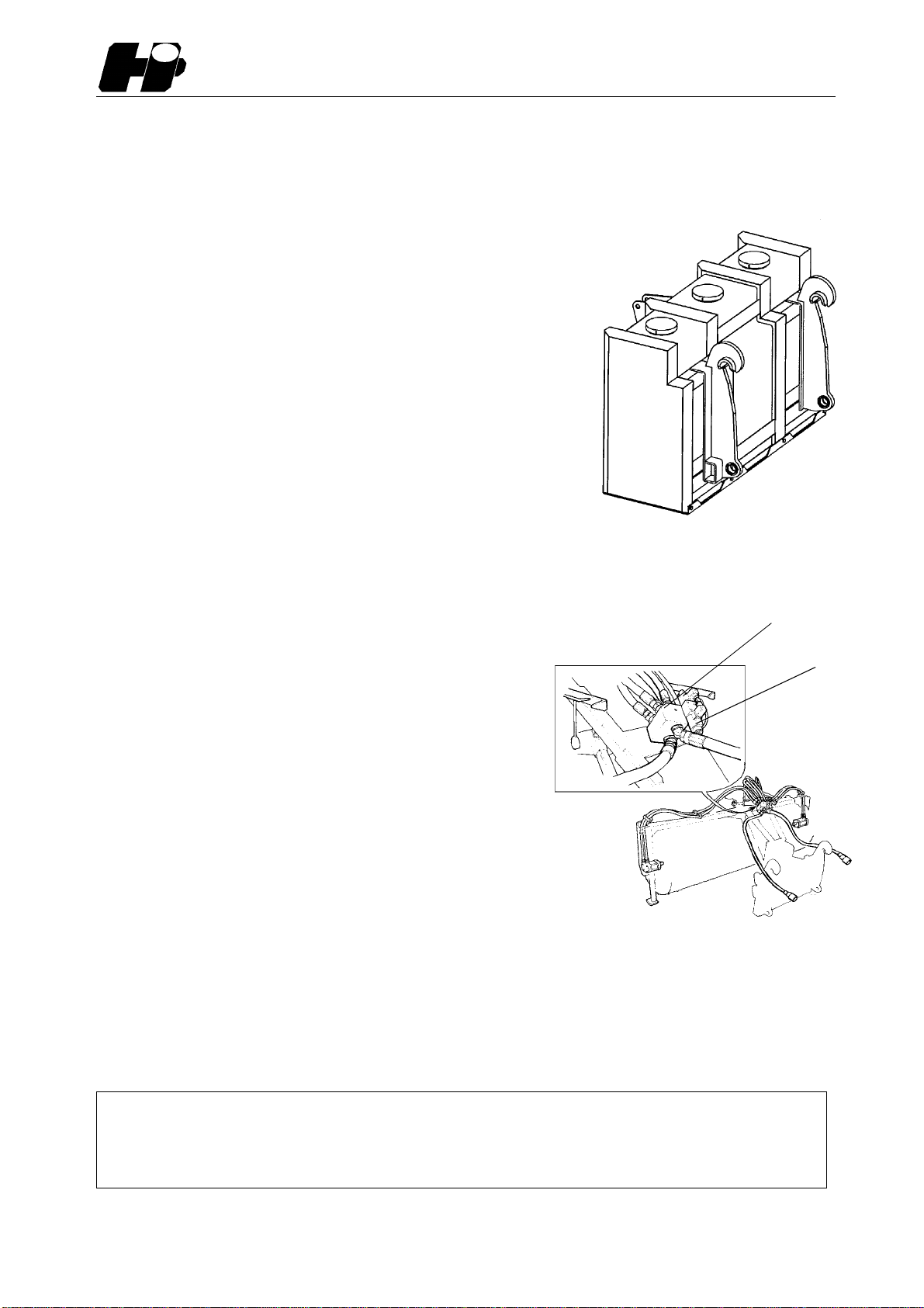
Disconnecting from carrier
1. Loosen the attachment bracket faucets before the
sweeper is placed on the ground to avoid damage on the
suspension system.
2. Lower and secure the support in parking position.
Attention! The sweeper brushes can be deformed if the
supports are not used when sweeper is parked.
3. Put down the sweeper on the ground.
4. Loosen the quick couplings for the 3:rd and 4:th hydrau-
lic functions alternatively hydraulic motor circuit and the ca-
ble.
8. Sweeper with even ground pressure
10. Sweeper tilted forwards
11. Supports in parking position
9. Sweeper tilted backwards