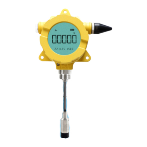
HOLYKELL 4800E User manual

ELECTROMAGNETIC FLOW METER
USER MANUAL
4800E 4800
4800E 4880E

Contents
Product description..............................................................................................................................1
Working principle..................................................................................................................................1
Features................................................................................................................................................ 1
Technical parameter............................................................................................................................2
Flange connection structure and installation dimensions..............................................................5
Flow range table.................................................................................................................................. 6
Instrument installation......................................................................................................................... 7
1. Installation location selection........................................................................................................ 7
2. Installation requirements................................................................................................................7
Electromagnetic Flow meter Converter Instruction Manual.......................................................... 9
1. The product function introduction................................................................................................. 9
2. Basic circuit of converter............................................................................................................. 11
3. Index of technical performance.................................................................................................. 11
4. Transmitter operation................................................................................................................... 14
5. Setting parameters....................................................................................................................... 26
6. Infrared telecontrol function keys............................................................................................... 36
7. Alarm information..........................................................................................................................36
8. Troubleshooting............................................................................................................................ 36
9. Encasement and reserve.............................................................................................................38

1
Product description
Smart electromagnetic flow meter is a high-performance, high-reliability flow meter. It used to
measure the volume flow of conductive liquid and slurry in closed pipelines. Widely used in steel,
electricity, petroleum, chemical industry, coal, metallurgy, papermaking, water supply and drainage, food,
pharmaceutical industry, etc.
Working principle
The measuring principle of electromagnetic flow meter is based on Faraday's law of electromagnetic
induction. The sensor is mainly composed of a measuring tube with an insulating lining, a pair of
electrodes installed by inserting the measuring tube wall, a pair of coils and an iron core to generate a
working magnetic field. When a conductive fluid flows through the measuring tube of the sensor, a
voltage signal proportional to the average flow rate of the fluid will be induced on the electrode. The
signal is operationally amplified and processed to achieve various display functions.
Features
●Measurements are not affected by fluid density, viscosity, temperature, pressure and conductivity.
●No obstacles in the measuring tube, no pressure loss, low requirements for straight pipe section.
●The LCD backlight type converter can be easily displayed and read in the sun or in a dark room.
●In harsh environments, parameters can be set via infrared touch buttons without opening the cover of
the converter (need to be customized).
●Flow meter with bidirectional measurement system, built-in three totalizers: positive total, reverse total
and total difference.
●It has various forms of output: current 4-20mA, pulse, frequency, rs-485, HART.
●The converter has self-diagnosis alarm output, no-load detection alarm output, flow upper and lower limit
alarm, batch control (need to be customized) and other alarm output functions.
●Not only for general processes, but also for the measurement of ore pulp, mud, coal slurry, paper pulp
and paste liquid.
●High-pressure electromagnetic flow sensor with PFA lining technology, resistant to high pressure and
negative pressure, especially suitable for petroleum, chemical and other industries.
●Explosion-proof instruments can be used in corresponding explosion-proof places.

2
Technical parameter
Item
Technical parameter
Main power
AC220V 50HZ/DC24V/DC12V/3.3V battery power supply
Power consumption
<15W (Supporting power consumption with sensors )
Display and buttons
Display in Chinese and English, can display instantaneous flow, accumulated flow
and alarm display (excitation open circuit alarm, empty pipe alarm, flow over limit
alarm). Four membrane touch switches for data setting
Counter
Forward total, reverse total
Output signal
Analog
output
Two-way, fully isolated 0~10mA/4~20mA
Load resistance: 0~1.5kΩ when 0~10mA; 0~750Ω when 4~20mA
Frequency
output
Forward and reverse flow output, the upper limit of output
frequency can be set within 1~5000Hz. Open collector
bidirectional output of transistor with photoelectric isolation. The
external power supply is not greater than 35V, and the maximum
current of the collector when it is turned on is 50mA
Alarm Output
Two-way open collector alarm output with photoelectric isolation
transistor. The external power supply is not greater than 35V, and
the maximum current of the collector when it is turned on is
250mA. Alarm status: fluid empty pipe, excitation disconnection,
flow overrun
Pulse output
Forward and reverse flow output, the output pulse upper limit can
reach 5000CP/S.
Pulse equivalent is 0.0001~1.0m³/P. The pulse width is
automatically set to 20ms or square wave. Open collector output
of transistor with photoelectric isolation. The external power
supply is not greater than 35V, and the maximum current of the
collector when conducting is 50mA
Matching accuracy
0.5%
Damping time
constant
Continuous variable from 0~100s (90%) time grading optional
Communication
Optional RS232C or RS485 serial communication interface, HART
communication protocol
Loss of power
The internal design of the instrument has a power-off clock, which can store 16
power-off records (10 years) (need to be customized)
Protection class
IP65(standard);IP68 can be customized for the split type(only for transmitter).
Explosion-proof
mark
Ex d ia [ia Ga] q IIC T6 Gb

3
Model Code Selection Table:
Code No.
Meter Type
4800
Segregate Type Electromagnetic Flow Meter,
4800E
Integrated Type Electromagnetic Flow Meter
4880
Sanitary Segregate Type Electromagnetic Flow Sensor
4880E
Sanitary Type Integrated Electromagnetic Flow Meter
Code No.
Nominal Diameter
4800
4800E
4880
4880E
10
DN10mm
●
●
○
○
15
DN15mm
●
●
●
●
20
DN20mm
●
●
●
●
25
DN25mm
●
●
●
●
32
DN32mm
●
●
○
○
40
DN40mm
●
●
○
○
50
DN50mm
●
●
○
○
…
…
●
●
○
○
150
DN150mm
●
●
○
○
200
DN200mm
●
●
○
○
250
DN250mm
●
●
○
○
300
DN300mm
●
●
○
○
…
…
●
●
○
○
1200
DN1200mm
●
●
○
○
2000
DN2000mm
●
●
○
○
Code No.
Power Supply
4800
4800E
4880
4880E
A
85V~265V AC
●
●
●
●
D
DC 24V
●
●
●
●
Code No.
Nominal Pressure
4800
4800E
4880
4880E
Y1
0.6MPa
●
●
●
●
Y2
1.0MPa
●
●
●
●
Y3
1.6MPa
●
●
●
●
Y4
2.5MPa
●
●
●
●
Y5
4.0MPa
●
●
●
●
Y7
16MPa(limited DN10-150)
●
●
○
○
Y8
20MPa(limited DN10-50)
●
●
○
○
Y9
25MPa(limited DN10-50)
●
●
○
○
Code No.
Communication Output
4800
4800E
4880
4880E
R
0~10mA.DC
●
●
●
●
M
4~20mA.DC
●
●
●
●
C
Pulse+4-20mA
●
●
●
●
T
RS485 MODBUS RTU
●
●
●
●
Q
RS-232C
●
●
●
●
A
4 ~ 20mA +RS485
MODBUS protocol
●
●
●
●

4
H
4 ~ 20mA.DC HART
protocol
●
●
●
●
G
GPRS wireless
communications
●
○
●
●
Code No.
Lining Materials
X2
Soft rubber
●
●
○
○
X3
Polychloroprene rubber
●
●
○
○
X4
Polyurethane rubber
●
●
○
○
X5
Teflon
●
●
○
○
X6
F46 poly perfluoro
ethylene ally
●
●
●
●
Code No.
Electrode Materials
B1
Stainless steel containing
molybdenum
●
●
●
●
B2
Hastelloy B alloy ( HB)
●
●
●
●
B3
Hastelloy C alloy ( HC)
●
●
●
●
B4
Titanium Ti
●
●
●
●
B5
Tantalum Ta
●
●
●
●
B6
Platinum Pt
●
●
●
●
Code No.
The Sensor Housing And Flange Materials
F1
Carbon steel
●
●
○
○
F2
Stainless steel
●
●
●
●
F3
Other materials
●
●
○
○
Code No.
Electronic Shell Protection Grade (Optional)
P1
IP65(standard)
●
●
●
●
P2
IP68(By customized)
●
○
●
○
Code No.
The Grounding Ring ( Optional)
R
Three-electrode Type
(Equal to ground ring)
●
●
●
●
Code No.
Explosion Proof Type ( Optional)
E
Explosion proof
type( 24v.DC)
○
●
○
●
Selection codes explanation
Model Code: 4800E50DY3MX5B1F1P1RE-L
4800E
50
D
Y3
M
X5
B1
F1
P1
R
E
L
Type Diameter Supply Pressure Output Lining Electrode Housing Grade Ground Explore Max
Proof Flow
Note: "●" on behalf of optional," ○" is mean not optional.

5
Flange connection structure and installation dimensions
Unit: mm
DN
L(PTFE)
L(Rubber/PFA/F46)
D
d1
n*d0
10
193
/
90
60
4*14
15
193
/
95
65
4*14
20
193
/
105
75
4*14
25
193
/
115
85
4*14
32
193
/
135
100
4*18
40
193
200
145
110
4*18
50
193
200
160
125
4*18
65
243
250
180
145
4*18
80
244
250
195
160
8*18
100
244
250
215
180
8*18
125
244
250
245
210
8*18
150
290
300
280
240
8*23
200
341
350
335
295
12*23
250
441
450
405
355
12*26
300
490
500
460
410
12*26
350
490
500
505
460
16*23
400
490
500
565
510
16*26
450
540
550
615
560
20*26
500
540
550
670
620
20*26
600
590
600
755
705
20*25
700
690
700
860
810
24*25
800
790
800
975
920
24*30
900
890
900
1075
1020
24*30
1000
990
1000
1175
1120
28*30
1200
1190
1200
1400
1340
32*34
1400
1390
1400
1620
1560
36*34
1600
1590
1600
1820
1760
40*34
1800
1790
1800
2046
1970
44*41
2000
1990
2000
2265
2180
48*48
(1)Instrument size error ± 2mm (2) The rated flange pressure of this table DN10-DN300: 1.6MPa
DN350-DN500: 1.0MPa ,DN600-DN2200: 0.6MPa.(3)Other flange standards are customized.

6
Flow range table
Flow range and Flow rate table
m/s
m3/h
mm
0.5
1
2
3
4
5
15(maximum)
10
0.14
0.28
0.27
0.85
1.13
1.41
4.24
10
0.14
0.28
0.27
0.85
1.13
1.41
4.24
15
0.32
0.64
1.27
1.91
2.54
3.18
9.54
20
0.57
1.13
2.26
3.39
4.52
5.65
16.96
25
0.88
1.77
3.53
5.30
7.07
8.84
26.51
32
1.45
2.90
5.79
8.69
11.58
14.48
43.43
40
2.26
4.52
9.05
13.57
18.10
22.62
67.86
50
3.53
7.07
14.14
21.21
28.27
35.34
106.03
65
5.97
11.95
23.89
35.84
47.78
59.73
179.19
80
9.05
18.10
36.19
54.29
72.38
90.48
271.43
100
14.14
28.27
56.55
84.82
113.10
141.37
424.12
125
22.09
44.18
88.36
132.54
176.71
220.89
662.68
150
31.09
63.62
127.23
190.85
254.47
318.09
954.26
200
56.55
113.10
226.19
339.29
452.39
565.49
1696.46
250
88.36
176.71
363.43
530.14
706.86
883.57
2650.72
300
127.23
254.47
508.94
763.41
1017.88
1272.35
3817.04
350
173.18
346.36
692.72
1039.08
1385.44
1731.80
5195.41
400
226.19
452.39
904.78
1357.17
1809.56
2261.96
6785.84
450
286.28
572.56
1145.11
1717.67
2290.22
2862.78
8588.33
500
353.43
706.86
1413.72
2120.58
2827.43
3534.29
10602.88
600
508.94
1017.88
2035.75
3053.63
4071.50
5089.38
15268.14
700
692.72
1385.44
2770.88
4156.33
5541.77
6927.21
20781.64
800
904.78
1809.56
3619.11
5428.67
7238.23
9047.79
27143.36
900
1145.11
2290.22
4580.44
6870.66
9160.88
11451.11
34353.32
1000
1413.72
2827.43
5654.87
8482.30
11309.73
14137.13
42411.50
1200
2035.75
4071.50
8143.01
12214.51
16286.02
20357.52
61072.56
1400
2770.88
5541.77
11083.54
16625.31
22167.08
27708.85
83126.54
1600
3617.11
7238.23
14476.46
21714.69
28952.92
36191.15
108573.44
1800
4580.44
9160.88
18321.77
27482.65
36643.54
45804.42
137413.26
2000
5654.87
11309.73
22619.47
33929.20
45238.93
56548.67
169646.00
2200
6842.39
13684.78
27369.56
41054.33
54739.11
68423.89
205217.66
2400
8143.01
16286.02
32572.03
48858.05
65144.07
81430.08
244290.24
2600
9556.72
19113.43
38226.85
57340.71
76453.71
95567.13
206701.40
2800
11083.54
22167.90
44334.15
66501.23
88668.31
110835.39
332506.16
3000
12723.45
25446.90
50893.80
76340.70
101787.60
127234.50
381703.50

7
Instrument installation
Choosing the correct installation location and adopting the correct installation method is the key to
using the electromagnetic flow meter. If the installation is wrong,
Not only will it affect the measurement effect, it will also affect the measurement accuracy, it will also
affect the life of the flow meter, and even damage the flow meter.
1. Installation location selection
In order to make the sensor work reliable and stable, the following requirements should be paid
attention to when choosing the installation location:
(1)
Try to avoid ferromagnetic objects and equipment with strong electromagnetic fields (such as
large motors, large transformers, etc.) to prevent magnetic fields from affecting transmission
The working magnetic field and flow signal of the sensor.
(2)
It should be installed in a dry and ventilated place as much as possible , and not in a place
with dampness and water.
(3)
Avoid sun and rain as much as possible, and avoid ambient temperature higher than 60℃
and relative humidity higher than 95%.
(4)
Choose a place that is convenient for maintenance and convenient for activities.
(5)
The flow meter should be installed at the back of the pump, not on the suction side; the valve
should be installed on the downstream side of the flow.
2. Installation requirements
For your correct measurement, you should pay attention to the following requirements when
selecting the location on the pipeline:
(1)
The sensor can be installed on a straight pipe, or on a horizontal or inclined pipe, but the
center connection of the two electrodes is required in a horizontal state.
2) The medium should flow in the full pipe at the installation position to avoid dissatisfied pipe and
gas adhering to the electrode.
(3)
For liquid-solid two-phase fluids, it is best to install vertically to make the sensor lining wear
evenly and prolong the service life.
(4)
When the medium at the installation position of the flow meter is not full, the method of
raising the back-end pipeline of the flow meter can be adopted to make it full.
Install flow meters at the high point and the water outlet.
(5)
Modify the installation method of the pipeline: When the flow rate of the medium does not
meet the requirements, a flow meter with a smaller diameter should be used.
Use reducer pipe or modify part of the pipe to make it the same diameter as the sensor, but the front
and rear straight pipe sections must at least meet the front straight pipe section ≥ 10DN, straight back
pipe ≥ 5DN (DN is pipe diameter).
(6 ) The front and rear straight pipe sections are ≥10DN before the flow meter and ≥5DN at the
back end.

8
3. Instrument wiring
●If the signal cable connected by split installation uses a customized dedicated cable, the shorter the
cable, the better.
●The excitation cable can choose Yz medium-sized rubber sheathed cable, and its length is the same as
the signal cable.
●Signal cables must be strictly separated from other power sources and cannot be laid in the same pipe.
●The signal cable and the excitation cable should be as short as possible, and the excess cables should
not be rolled together. The excess cables should be cut off, and
●Re-solder the joints.
●When the cable mediates the sensor electrical interface, it is made into a U-shape at the port, which
can prevent rainwater from penetrating into the sensor.
Install at the lowest point and vertical upward
direction Don’t install at the highest point and
vertical downward direction
Install exhaust valve at the downstream of
flow meter when drop is more than 5m
Installed at the lowest point when used in
open drain pipe
Need 10D of upstream and 5D of downstream
The sensor cannot be installed at the inlet of
the pump. It can be installed at the outlet
It should be installed on the rise of the pipeline

9
Electromagnetic Flow meter Converter Instruction Manual
1.
The product function introduction
1.1 Basic function
●Low-frequency square-wave exciting,exciting frequency:1/16 power frequency,1/20power
frequency,1/25 power frequency;
●High-frequency square-wave exciting ,exciting frequency:1/2 power frequency (for grouting liquid
measure);
●Exciting current can be selected for 125mA,187.5mA,250mA,500mA;
●No need to add empty pipeline measurement, and can measure continuously, alarm by fixed value;
●Current speed range: 0.1 --- 15m/s,current speed resolution:0.5mm/s;
●AC high-frequency switching power,range of voltage:85VAC --- 250VAC;
●DC 24V switching power,range of voltage: 20VDC --- 36VDC;
●Network function:MODBUS,GPRS,PROFIBUS,Analog Loop Communication interface(choose);
●Chinese or English displaying mode, (other languages can be set);
●Three internal accumulators: positive total accumulation, reverse total accumulation, positive and
negative accumulation difference.
1.2 Especial function
Recording time when power turn-off, to record power broken time of instrument system automatically and
recruit to count the missing flux;
Recording function of hourly gross, to record the flux gross by hour, fit for timed measure;
Infrared handing remote control keyboard,all the functions of far-untouched controlling converter.
1.3 Normal operating conditions
Ambient Temperature Ranges:fission –10~+60℃;
Relative Humidity:5%~90%;
Power Supply: 85~250V,45~63Hz ( single-phase AC).
Dissipation Power: <20W(After connecting sensor).

10
1.4 Type of connecting with sensors
●The integrated Circular shells: Circular shells, shells connect with the flange directly, explosion-proof;
●The integrated squared shells: squared shells, shells connect with the flange directly;
●The split squared shells: squared shells (hang on the wall), Signal converters connect with cable of sensor;
1.5 Plot of installing measure
Fig.1 Exterior size of the integrated Circular shells
Fig.2 Exterior size of the split squared shells

11
2.
Basic circuit of converter
Fig.2. 1 Structure Of Converter’s Circuit
The converter can supply exciting current to the coil in the sensor of electromagnetic Flow meter,the
head amplifier amplifies the electromotive force from the sensor and converts it into standard signals of
current or frequency so that the signals can be used for displaying, controlling and processing. See
structure of converter circuit shown in Fig.2.1。
3.
Index of technical performance
3.1 Standard of implement
The design, production and instrument of Electromagnetic Flow meter Converter implement
《ISO 9104:1991》and 《ISO 6817:1992》.
3.2 Basic parameters and performance index
3.2.1 Pipe’s inside diameter of relative sensor (mm):
3,6,10,15,20,25,32,40,50,65,80,100,125,150,200,250,300,350,400,450,500,600,700,800,900,1000,1200,
1400,1600,1800,2000,2200,2400,2500,2600,2800,3000;
Keyboard
LCD
Display
EEROM
ROM
preampli
fier
exciting circuit
85~260V
45~63Hz
Switching
Power Supply
4-20mA or
0-10mA
1-5000Hz
Frequency or
Pulse Output
Current Output
Pulse Output
OC Gate Status
Output
Status
Control
RS485 .etc
Communication
Interface
A/D
32 bit
CPU

12
3.2.2 Request of relative sensor
Sensitivity of sensor signal: under 1m/s, output 150µV ~200µV;
For electromagnetic flow meter signal converters, there are four currents of 62.5mA in exciting loop,
which make up of 250mA, and every 62.5mA is controlled by one 20Ω exact resistance. So user can
choose different exciting current by changing the number of exact resistance.
The current will be 250mA when the signal converters leave factory, as such, if there are three exact
resistance, the current will be 187.5 mA; if two, 125mA;
Resistance of sensor exciting coil:
500mA exciting current:20 ~ 30Ω;
250mA exciting current:50 ~ 60Ω;
187mA exciting current:60 ~ 80Ω;
125mA exciting current:100~20Ω;
3.2.3 Measure precision for assembly
Table 3.1 VS:Setting measurement range (m/s)
Diameter(mm)
Range(m/s)
Accuracy
3~20
≤0.3
±0.25%FS
0.3~1
±1.0R
1~15
±0.5%R
25 ~600
0.1~0.3
±0.25%FS
0.3~1
±0.5%R
1~15
±0.3%R
700~3000
≤0.3
±0.25%FS
0.3~1
±1.0%R
1~15
±0.5%R
%FS:for relative ranges;
%R:for relative value of measurement
3.2.4 Simulated current output
Load resistor: 0~750Ω (4~20mA). Basic Errors: 0.1%±10μA.

13
3.2.5 Digital frequency output
Frequency output range: 1~5000Hz;
Output electric isolate: Photoelectric isolate. Isolate voltage: > 1000VDC;
Frequency output drive: output by field-effect transistors, the highest subjected voltage is 36VDC ,
maximum of output current is 250mA.
3.2.6 Digital pulse output
Pulse output range: 0 ~100 pulse/s. (When higher than upper limit, pulse will lose);
Pulse output value: 0.001~1.000m3 / cp 0.001~1.000 Ltr / cp
0.001~1.000USG / cp, 0.001~1.000UKG / cp;
Pulse output width: 50ms,
Pulse output isolate: photo electricity isolate. Isolate voltage: > 1000VDC;
Pulse output drive: output by field-effect transistors, the highest subjected voltage is 36VDC,
maximum of output current is 250mA.
3.2.7Alarm output
Alarm output junction:ALMH--- upper limit; ALML--- lower limit; Output isolate: photo electricity isolate.
Isolate voltage: > 1000VDC;
Alarm output drive: output by Darlington pipe, the highest subjected voltage is 36VDC , maximum of
output current is 250mA.
3.2.8 Digital communication port and protocol MODBUS interface: format of RTU.
3.2.9 Analog Loop Communication interface: designed by standard of Analog Loop Communication , if
you choose our hand held unit , you can display the measure value on line, and setting the
parameters.
3.2.10 Electric isolate
Insulated voltage between simulated input and simulated output should be higher than 500V;
Insulated voltage between simulated input and alarm power supply should be higher than 500V;
Insulated voltage between simulated input and AC power supply should be higher than 500V;
Insulated voltage between simulated output and AC power supply should be higher than 500V;
Insulated voltage between simulated output and earth should be higher than 500V;
Insulated voltage between pulse output and AC power supply should be higher than 500V;
Insulated voltage between pulse output and earth should be higher than 500V;

14
Insulated voltage between alarm output and AC power supply should be higher than 500V;
Insulated voltage between alarm output and earth should be higher than 500V;
4.
Transmitter operation
4.1 Key and display
4.1.1 Squared define keys and LCD screen display
Fig. 4.1 (c) Keys on squared panel and large LCD display:
4.1.2 Rotundity define keys and LCD screen display
Fig. 4.1(d) Keys on Circular panel and big LCD display

15
Note: When measuring, pushing down “Compound Key + Enter” will appear password of changing state,
base on distinction of secrecy, and change the password as we provide. Then pushing
“Compound Key + Enter” again, and you can inter the state of setting parameter. If want to return
to the running state, push “Enter” for several seconds.
4.2 Section picture of conversion
Fig.4.2 (c) L-mag 211B-4 Key Fig.4.2 (d) L-mag 411B-4 Key
4.3 Connections of sensor
4.3.1
Connectors and labels for the squared
Fig.4.3 (a) Connectors for 211B

16
Labels of connectors in squared model
4.3.2
Signal lines and labels in squared model
Fig.4.3 (b) Connection and labels of signal lines in squad model
4.3.3
Links and labels of connectors in Circular Model

17
L2 L1
COM I+ COM P+ AH AL
FUSE
T+ G T-
+
+
+
+
+
Fig.4.3(c) Connectors in circular model
Symbols and Description of Connectors in Circular Pane
I+:
Output Current for Flow Measurement
COM:
Output Current (Ground) for Flow Measurement
P+:
Frequency(Pulse) Output for Bi-directional Flow
COM:
Frequency (Pulse) Output (Ground)
AL:
Alarm Output for Low Limit
AH:
Alarm Output for Upper Limit
COM:
Alarm Output (Ground)
FUSE:
Fuse for Power Supply
T+:
+Communication Input Signal(RS485-A)
T-:
-Communication Input Signal(RS485-B)
G
RS232 Communication Ground
L1:
220V(24V)Power Supply
L2:
220V(24V)Power Supply
4.3.4
Labels and connection of signal lines in Circular model

18
Fig.4.3 (d) Labels and connection of signal lines in Circular model
Signal lines labels in Circular model:
White twisted-pair cable (for exciting current): 12 Conductors (Red)
12 Conductors (Black)
Gray shielded twisted-pair cable: 10 Conductors (Red) connected to “Signals 1”
13 Conductors (White) connected to “Signals 2”
Shielded Conductor connected to “Signal Ground”
4.4 Characteristic and connection of cable
4.4.1
Flux signal line
When separated models of converters are assembled with sensors for measuring flow of fluid which
conductivity is larger than 15μS/cm, PVVP 2*0.2 mm2model cable ( metal shielded signal cable covered
with PVC) can be used as communication cable for flow signals. The length of signal cable should be
less than 100m. Signal cables have to be connected to sensors that were assembled by producers.
Connections of signal cables are shown in Fig. 4.3(b) for squire-shaped models and Fig. 4.3(d) for circle-
shaped models, respectively.
The converter can output equivalent level of shielded exciting signal voltage so that interference to
flow measurement signals can reduced by means of lowering the distributed capacitance of
communication cable. When measured conductivity is less than 15μS/cm or signals are transferred in
remote distances, double-conductor and double-shielded signal cable at equivalent level of voltage can
be used. For example, special STT3200 cable or BTS model signal cable (triple-shielded) can be used
for signal communication.
4.4.2
Exciting current cable
Two conductor and insulating rubber- covered cables can be used as exciting current cables.
This manual suits for next models
2
Table of contents
Other HOLYKELL Measuring Instrument manuals