manuals.online logo
Brands
  1. Home
  2. •
  3. Brands
  4. •
  5. Honeywell
  6. •
  7. Control Unit
  8. •
  9. Honeywell NOTIFIER 020-772 User manual

Honeywell NOTIFIER 020-772 User manual

Check your equipment....
Take suitable anti-static precautions, such as wearing a grounded
wrist strap, when following ALL instructions. Remove all packaging
from the kit and ensure that it has not been damaged in transit (and
that no items are missing - see checklist on the left) before
proceeding any further. If no damage is evident, proceed using the
instructions below. In the unlikely event that damage has occurred
or items are missing, DO NOT PROCEED, contact your supplier
and refer to the panel’s Installation, Commissioning &
To fit/replace the 4-Way Sounder PCB, configure it (see page 3), then
proceed as follows:
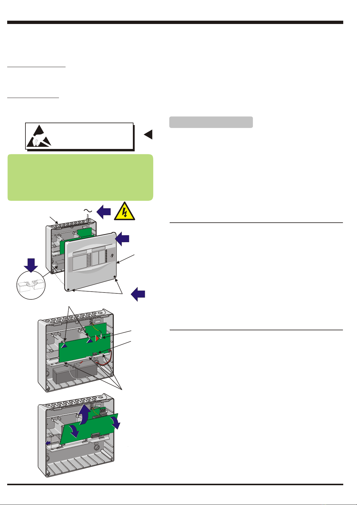
1Only carry out this procedure when mains power to the panel has been
isolated.
2Use a 4mm hex key to release the two socket-headed screws (A) that
secure the cover (B) to the back box (C).
3Carefully withdraw the cover from the back box. Store cover safely.
4Ensure the batteries (D) are disconnected.
5If replacing the 4-Way Sounder PCB, temporarily disconnect all
external cables to the Main PCB.
Procedure for Fitting/Replacing the 4-Way Sounder
PCB
Your 4-Way Sounder PCB Kit, PN: 020-772 should
contain:
4-Way Sounder PCB PN: 124-372
16-way Ribbon Cable (x1) PN: 082-252-002
Nylon Spacers (x2) PN: 423-262
Nylon locking rivets (x2) PN: 423-261
Fitting/Replacing the 4-Way Sounder PCB
1
6Disconnect the earth lead from the right-angled, blade connector (E)
located at the top right-hand corner of the Main PCB.
7Carefully push up the two PCB-retaining clips (F) until the top edge of
the Main PCB is free to move - the bottom edge of the PCB is still
located by the three tabs (G).
Note: If a 2-Way Relay PCB is fitted, slide it to the left to disengage
socket connector SK2 on the Main PCB. Once disengaged, there
is no need to remove the 2-Way Relay PCB from the panel.
8Leave the ribbon cable connected at connector SK4 (H) on the Main
PCB, disconnect the ribbon cable at socket connector SK2 on the PSU
PCB.
DO NOT forget to reconnect this cable before re-fitting the main
PCB.
9Gently pull the top of the Main PCB away from the back box and lift the
PCB clear of the back box and store safely.
Removing the Main PCB
AA
CC
BB
Main
PCB
Main
PCB
1
0
1
1
3
3
2
2
4
4DD
Main PCB
EE
GG
FF
HH
For clarity,
batteries are
not shown.
For clarity,
batteries are
not shown.
99
77
OBSERVE PRECAUTIONS FOR
HANDLING ELECTROSTATIC
SENSITIVE DEVICES
OBSERVE PRECAUTIONS FOR
HANDLING ELECTROSTATIC
SENSITIVE DEVICES
ATTENTIONATTENTION
The 4-Way Sounder PCB (kit PN: 020-772) supports four configurable monitored outputs and two configurable digital
inputs. Various preset combinations of input and output functions are selected via a DIP switch. Up to two,
independently-configurable 4-Way Sounder PCBs may be fitted in the fire control panel. Provision is made for
connecting an SST LED box.
Output options are: sounder, ÜE transmission circuit, SST extinguishing system (three output circuits are used: one
for SST output and two for SST inputs), fault routing or fire routing. To connect an SST, a Routing Termination kit (PN:
020-773) and LED Display Box (English version PN: 020-769-001 or German version 020-769) are also required. The 4-
Way Sounder PCB detects partial open and short circuits on the output circuits, to meet EN54-13 requirements.
Input options are: fire transmission confirmed, fault transmission confirmed, class change or day mode.
Depending upon its output load, the PCB can be powered from the panel or from an external dc power supply, as set by a
jumper link.
997-536-000-2, Issue 2 July 2009
Fitting the 4-Way Sounder PCB
Fitting the Second-layer 4-Way Sounder PCB
Fitting/Replacing the 4-Way Sounder PCB
10 Inspect the 4-Way Sounder PCB (I). If there is no evidence of damage,
proceed with fitting.
11 If a second-layer PCB is being fitted go to step 17 before continuing.
Otherwise, connect the 16-way ribbon cable (J) to the outermost
connector SK2 (K). Observe polarity. Slide the ferrite along the ribbon
cable so that it is near to SK2.
12 With the PCB (I) correctly orientated - the wiring connectors must be at
the top - offer it to the space to the left of the PSU PCB (L).
13 Align and locate the 4-Way Sounder PCB in the two locating slots (M) and
once located, push the top of the PCB to engage the two retaining spring
clips (N).
14 Push the PCB home until secure. The two upper holes on the PCB
should locate cleanly on the lugs (O).
15 Connect the other end of the 16-way ribbon cable (J) to SK1 on the PSU
PCB.
16 If a second-layer PCB (either 8-way Relay or 4-way Sounder) is not
being fitted, the Main PCB can now be re-fitted. Ensure that:
i The ribbon cable is re-connected to SK2 on the PSU PCB.
ii The PCB is correctly aligned with the rebates in the side wall ribs
before gently pushing it home.
17 With reference to the drawings immediately at left, fit two spacers in the
lower of the two top pairs of holes on the first-layer PCB as follows:
a. Insert each rivet (P) in the holes as far as the collar (this is about half
way along the rivet) and no further at this stage.
b. Place the larger end of the spacer (Q) - the end with the locating hole
- over the partially-inserted rivet until flush with the face of the PCB.
c. Holding the spacer against the PCB, now push the rivet fully home;
the jaws of the rivet expand inside the spacer to lock it to the PCB.
Ensure the spacer is orientated as shown to clear any components.
18 Inspect the 4-Way Sounder PCB to be fitted in the second-layer
position. If there is no evidence of damage, proceed as follows.
19 Connect the 16-way ribbon cable (S) - observe polarity - to connector
SK1 of the first-layer 4-Way Sounder PCB (I).
20 Offer the bottom edge of the second-layer PCB towards the two lower
locating slots (T) and connect the other end - observe polarity - of the
ribbon cable to the connector SK2 located on the second-layer 4-Way
PCB. Slide the ferrite to be beside SK2, closer than in step 11.
21 Align and locate the 4-Way Sounder PCB in the two locating slots (T)
and line up the two spacers with the upper two holes on the second-
layer PCB and push the top part of the PCB so that the spacers engage
and locate in the holes.
22 Re-fit the Main PCB and re-connect the ribbon cable to the PSU PCB.
23 Connect all external wiring to the 4-Way Sounder PCB(s).
24 Re-connect all external wiring to the Main PCB.
25 Apply power and connect batteries.
26 Ensure any faults are cleared before replacing the cover.
N
O
With the Main PCB removed....
2
T
Follow steps 10 to16 if only fitting one 4-way Sounder PCB. If fitting two 4-
way Sounder PCBs follow steps 10 and 11 then go step 17 before
continuing with steps 12 - 16.
If two PCBs are being fitted use the spacer and rivet (with collar) supplied
with the kit. Where a faulty PCB being replaced, use the spacers and rivets
supplied with this kit. Discard previous type of spacers (i.e without rivet)
where used.
1212
1212
M
L
I
K
J
1717
P, R Q
QR
P
a
bc
SK2
2020
S
1919
997-536-000-2, Issue 2 July 2009
1
0
1234567 8
Fitting/Replacing the 4-Way Sounder PCB
Configuration Options
By default, the PCB is configured as follows:
All circuits are sounders, activated on first fire, any zone. Sounders steady
and load >250mA. Digital inputs set to Class Change and Day Mode.
If other options are required, configure links and DIP switch before fitting
the PCB into the panel. Perform configuration in the sequence given below:
1 Jumper link
Determine whether power is obtained from the panel or from an
external dc power supply unit (PSU) - refer to 'Specification' on page 4.
2 Earth link
Remove if the external PSU's output is referenced to earth.
3 DIP switch - circuit configuration functions
Use switches 1 to 4 to configure the four circuits.
4 DIP switch - other configuration options
Switch 5 determines whether the sounders are steady or pulsing.
Switch 6 must be set according to the maximum load current being
drawn on an circuit (if configured as an output). This is used by the PCB
to detect partial open and short circuits.
Switch 7 determines the function of digital input circuit 1.
Switch 8 determines the function of digital input circuit 2.
3
+ 1 - + 2 - + 3 - + 4 -
+-
TB3TB2 TB4
TB1
PL1
PL2
SK1
SK2
IN-CIRC
PROGR.
FS02 DEOL MON. SOUNDER PCB
SW1
JP1
AB
1
1
234567 8
12!
0V
0
Position A: Sounder PCB is
powered from panel via ribbon cable.
Position B: Sounder PCB is
powered from external PSU (see
Specification).
If an external PSU with its output
referenced to earth is used (i.e.
continuity between mains earth and 0V),
remove R63 to isolate the input. This
prevents earth faults from occurring.
1: PSU Jumper
Link
2: External PSU
Earth Link
JP1
AB
R63
4: Other Configuration Options
DIP switches: 5-8 settings Function
5678
Steady/Pulsing
0 0 0 0 Steady sounders
1 0 0 0 Pulsing sounders, 1second on, 1 second off
Sounders > 250mA
0 0 0 0 Sounders > 250mA. Use this setting if one or more of the output circuits has a load current of 250mA or above.
0 1 0 0 Sounders < 250mA. Use this setting if none of the output circuits has a load current greater than 250mA.
Digital input circuit 1
0 0 0 0 Class change
0 0 1 0 Fire transmission confirmed (monitored fire routing output)
Digital input circuit 2
0 0 0 0 Day mode
0 0 0 1 Fault transmission confirmed (monitored fault routing output)
0 0 0 0 0
1 1 0 0 0
2 0 1 0 0
3 1 1 0 0
4 0 0 1 0
5 1 0 1 0
6 0 1 1 0
7 1 1 1 0
8 0 0 0 1
9 1 0 0 1
10 0 1 0 1
11 1 1 0 1
12 0 0 1 1
13 1 0 1 1
14 0 1 1 1
15 1 1 1 1
1 2 3 4
Option
DIP switch Settings
Circuit 1 Circuit 2 Circuit 3 Circuit 4
Functions
Any zone
Any zone
Zone 1
Zone 5
Zone 1
Zone 2
Zone 1 or
Zone 2
Zone 3 or
Zone 4
Zone 5 or
Zone 6 Zone 7 or
Zone 8
Zone 7 and
Zone 8
Zone 5 and
Zone 6
Zone 5 and
Zone 7
Zone 6 and
Zone 8
Zone 1 and
Zone 2
Zone 3 and
Zone 4
Zone 3 and
Zone 5
Zone 4 and
Zone 6
Zone 1 and
Zone 3
Zone 2 and
Zone 4
Any zone
Any zone
Any zone
Any zone
Any zone
Any zone
Any zone
Any zone
Any MCP
Zone Any Detector
Zone
Zone 2 Zone 3
Zone 7
Zone 7
Zone 5
Zone 6 Zone 8
Zone 8
Zone 3
Zone 6
Zone 4
Zone 4
Any zone
Any zone Any zone
SST Operated
SST Fault
Any zone
Any zone
3: DIP Switch - Circuit Configuration Functions
Sounder activated on first fire in Zone n
Sounder delayed on first fire in Zone n
Sounder activated on second fire in
Zone n
Fire Routing
Output
Fault Routing
Output
ÜE
Output SST
Output
ÜE
Input
SST
Input
Key
RESET OUT
200R
200R
Return Signal
(unlatched)
Return Signal
(latched)
997-536-000-2, Issue 2 July 2009
Fitting/Replacing the 4-Way Sounder PCB
4
Specification
Outputs:
Sounder PCB outputs: 26 - 28.5V dc
If DIP switch6 is set to>250mA: 4 x 1A (maximum of 1.5Ain total for 2
or more outputs)
If DIP switch 6 is set to <250mA: 4 x 250mA
Digital Inputs: 2 x 5V - 32V dc
Up to two 4-Way Sounder PCBs may be fitted in the panel. If it is
intended to install an 8-way Relay PCB and a 4-way Sounder
PCB, the Relay PCB must be in the first (innermost) position.
Each 4-Way Sounder PCB communicates with the PSU PCB via 16-way
ribbon cables in a daisy-chain arrangement.
External power supply unit (if used):
Sounder PCB input: 20-30V dc, 5A
Compliancy: EN54 Part 4 with power status volt-free contact
(normally closed when there are no faults present)
Max Current (per PCB):
Quiescent: 47mA
Alarm/all active: 1547mA
External Wiring
Configurable Circuits
Typical wiring examples are given below. The functions available on a
particular circuit are determined by the configuration options described on
the previous page.
The PCB is supplied with an end-of-line diode across each circuit
connector. Remove these diodes and either (depending upon the usage of
the circuit) place across the end-of-line, or discard if not required in this
usage.
Digital Inputs
Typical wiring examples are given below. The functions available on a
particular input are determined by the configuration options described on
the previous page.
External PSU
If an external PSU is being used, connect the dc input as shown at left, and
the fault input as shown below. Links JP1 and R63 must be set correctly as
described on the previous page.
+ 1 - + 2 - + 3 - + 4 -
+-
TB3TB2 TB4
TB1
PL1
PL2
SK1
SK2
IN-CIRC
FS02 DEOL
MON. SOUNDER PCB
SW1
JP1
AB
1
1
234567 8
12SST
0V
0
20 - 30V dc, 5A
External Power
Input
-
+
+
-
+ 1 - + 2 -
Output Output Ouput Output
circuit 1 circuit 2 circuit 3 circuit 4
OUTPUT CIRCUIT APPLICATIONS:
Typical connections
+ 3 - + 4 -
+ 1 -
+ 1 -
+ 2 -
+ 2 -
+ 3 -
+ 3 -
+ 4 -
+ 4 -
ÜE
-
+
-
+
SOUNDERS FIRE/FAULT ROUTING
SST
This connection is provided
for LED box (English PN:
020-769-001 or German PN:
020-769).
SST LED Box
Connection
Note: + = active polarity
Haupt-
melder
ÜE
O/P
LEDs
Output channel 1 fault
Output channel 2 fault
Output channel 3 fault
Output channel 4 fault
Heartbeat
Normal: 0.5s on, 5 sec off
Panel/PCB Comms fault:
flashes at 1Hz, 50% duty
cycle
Heartbeat LED is green,
all others are yellow.
Fire
Routing Fault
Routing
KIT
020-
773
O/P
SST
Operated
SST
!!
Digital input circuit 1. Must be linked
to 0V if not used.
Digital input circuit 2. Must be linked
to 0V if not used.
1
2
DIGITAL INPUTS AND
EXTERNAL PSU
FAULT INPUT
Power fault output from EN54-4
compliant PSU:
Note: Must be linked to 0V if internal
PSU is used.
Connect normally closed to this
terminal.
Connect common to this terminal.
0V
120V
PROGR.
OUTPUT & INPUT CIRCUIT APPLICATIONS:
Typical connections
SST
FAULT
ÜE
Operated
997-536-000-2, Issue 2 July 2009

Other Honeywell Control Unit manuals

Honeywell CentraLine CLCM1T User manual

Honeywell

Honeywell CentraLine CLCM1T User manual

Honeywell EXCEL CARE 5000 User manual

Honeywell

Honeywell EXCEL CARE 5000 User manual

Honeywell Braukmann D05 User manual

Honeywell

Honeywell Braukmann D05 User manual

Honeywell V8043A1312/U User manual

Honeywell

Honeywell V8043A1312/U User manual

Honeywell PEHA 940 AMA User manual

Honeywell

Honeywell PEHA 940 AMA User manual

Honeywell 7800 SERIES User manual

Honeywell

Honeywell 7800 SERIES User manual

Honeywell PRO4200 User manual

Honeywell

Honeywell PRO4200 User manual

Honeywell SK-Mon-10 User manual

Honeywell

Honeywell SK-Mon-10 User manual

Honeywell S89C User manual

Honeywell

Honeywell S89C User manual

Honeywell Ex-Or CDH8U5 Installation and operation manual

Honeywell

Honeywell Ex-Or CDH8U5 Installation and operation manual

Honeywell DCCC6500 User manual

Honeywell

Honeywell DCCC6500 User manual

Honeywell GSMVLP5 Assembly instructions

Honeywell

Honeywell GSMVLP5 Assembly instructions

Honeywell 3GL User manual

Honeywell

Honeywell 3GL User manual

Honeywell RV181 User manual

Honeywell

Honeywell RV181 User manual

Honeywell RV283P User manual

Honeywell

Honeywell RV283P User manual

Honeywell M6410A Operation manual

Honeywell

Honeywell M6410A Operation manual

Honeywell NetAXS User manual

Honeywell

Honeywell NetAXS User manual

Honeywell RA890F Protectorelay Primary Control Installation guide

Honeywell

Honeywell RA890F Protectorelay Primary Control Installation guide

Honeywell V305 Series User manual

Honeywell

Honeywell V305 Series User manual

Honeywell Kromschroder BCM 400 B1 Series User manual

Honeywell

Honeywell Kromschroder BCM 400 B1 Series User manual

Honeywell S7800A1167 User manual

Honeywell

Honeywell S7800A1167 User manual

Honeywell DR 300 User manual

Honeywell

Honeywell DR 300 User manual

Honeywell PENA D MLS2000SSP Installation and operation manual

Honeywell

Honeywell PENA D MLS2000SSP Installation and operation manual

Honeywell JADE W7220 Operation and maintenance manual

Honeywell

Honeywell JADE W7220 Operation and maintenance manual

Popular Control Unit manuals by other brands

Masterclock RC500 user manual

Masterclock

Masterclock RC500 user manual

Allen-Bradley ControlNet ControlLogix 1756 user manual

Allen-Bradley

Allen-Bradley ControlNet ControlLogix 1756 user manual

Telefrang SIOX T05 manual

Telefrang

Telefrang SIOX T05 manual

Siemens SINUMERIK 840D Description of Functions

Siemens

Siemens SINUMERIK 840D Description of Functions

Cognex DataMan 50 reference guide

Cognex

Cognex DataMan 50 reference guide

Bosch AMC2 4W-EXT installation manual

Bosch

Bosch AMC2 4W-EXT installation manual

DAB E2D 2,6 M Instruction for installation and maintenance

DAB

DAB E2D 2,6 M Instruction for installation and maintenance

AzureWave AW-CU300A V3 Getting started guide

AzureWave

AzureWave AW-CU300A V3 Getting started guide

Charles 3652-62 manual

Charles

Charles 3652-62 manual

Saitek CF5Q Series manual

Saitek

Saitek CF5Q Series manual

Universal HS-303 instruction manual

Universal

Universal HS-303 instruction manual

Graco Series A instructions

Graco

Graco Series A instructions

turck excom-RMD1-BU quick start guide

turck

turck excom-RMD1-BU quick start guide

Quantum Rehab Network Adapter Dynamic DX Basic operation instructions

Quantum Rehab

Quantum Rehab Network Adapter Dynamic DX Basic operation instructions

Cistermiser IRC installation guide

Cistermiser

Cistermiser IRC installation guide

Allen-Bradley ArmorBlock 1732E-12X4M12QCDR Wiring diagrams

Allen-Bradley

Allen-Bradley ArmorBlock 1732E-12X4M12QCDR Wiring diagrams

FAAC 724 D-24V Instructions for use

FAAC

FAAC 724 D-24V Instructions for use

Deif Delomatic 4 AOP-2 Replacement instructions

Deif

Deif Delomatic 4 AOP-2 Replacement instructions

manuals.online logo
manuals.online logoBrands
  • About & Mission
  • Contact us
  • Privacy Policy
  • Terms and Conditions

Copyright 2025 Manuals.Online. All Rights Reserved.