HONEYWELL
HONEYWELLHONEYWELL
HONEYWELL
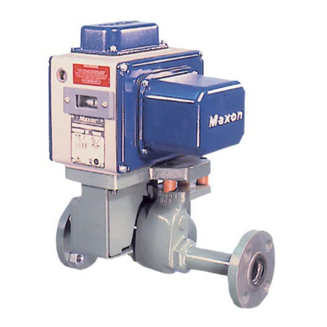
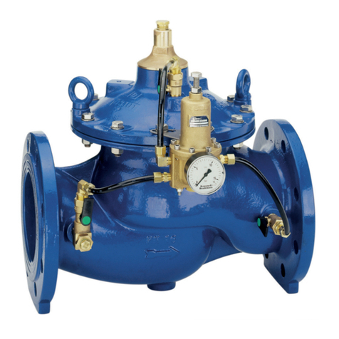
CLASS “A” COMBINATION VALVES
VQ400M-Series
EN2R9081-C
October 2009
2
CONTENTS
VQ400M SERIES ........................................................... 1
CLASS “A” COMBINATION VALVES ......................... 1
APPLICATION................................................................ 1
Contents......................................................................... 2
FEATURES .................................................................... 2
DESCRIPTION............................................................... 3
SPECIFICATION............................................................ 3
Models ........................................................................ 3
Dimensions................................................................. 3
Pipe sizes.................................................................... 4
Capacity...................................................................... 4
Connections................................................................ 4
Torsion and bending stress......................................... 4
Supply voltages........................................................... 4
Electrical equipment.................................................... 4
Electrical connections ................................................. 5
Ambient temperature range ........................................ 5
Coil insulation solenoid valves.................................... 5
Enclosure.................................................................... 5
Body material.............................................................. 5
Closing spring ............................................................. 5
Valve plunger.............................................................. 5
Seals and gaskets....................................................... 5
Power consumption .................................................... 5
PERFORMANCE CHARACTERISTICS......................... 6
Opening time............................................................... 6
Closing time................................................................ 6
Maximum working frequency ...................................... 6
Duty cycle ................................................................... 6
Operational voltage range........................................... 6
Designed life time ....................................................... 6
CAPACITY CURVES...................................................... 7
INSTALLATION.............................................................. 8
IMPORTANT............................................................... 8
WARNING................................................................... 8
Maintenance and service............................................ 8
Mounting position........................................................ 8
Mounting location........................................................ 8
Main gas connection flanged valves........................... 9
WARNING!.................................................................. 9
Electrical connection................................................... 9
WARNING................................................................... 9
Wiring.......................................................................... 9
ADJUSTMENTS AND FINAL CHECKOUT .................. 11
CAUTION.................................................................. 11
2nd main valve fast opening....................................... 11
2nd main valve slow opening..................................... 11
IMPORTANT............................................................. 11
Final checkout of the installation............................... 12
OPTION INSTALLATION ............................................. 13
WARNING................................................................. 13
CONSTRUCTION AND WORKING PRINCIPLES........ 13
ORDERING INFORMATION ........................................ 14
NOTE........................................................................ 14
Replacement of parts.................................................... 15
Warning..................................................................... 15
Recommended accessories ......................................... 15
APPROVALS................................................................ 17
Declaration of Conformity.......................................... 17
FEATURES
•Class “A” safety combination valve for
control of gaseous fluids in gas consuming
appliances in accordance with international
standards.
•Main body with two gas valves with single
seat.
•Possibility of installing internal by-pass
valve to achieve high-low flame control.
•Possibility of installing internal or external
pilot valve.
•Possibility of installing vent valve.
•Possibility of installing flanged minimum
and maximum pressure switches.
•Possibility of installing valve Proving
System (VPS).
•Possibility of mounting Closed Position
Indication switch (CPI) at bottom of safety
valve V1 and / or valve V2.
•Closing time: < 1 second.
•Coils field replaceable.
•Coils suitable for permanent energizing.
•Fine mesh screen between inlet flange and
main body (optional).
•Various pressure tap points at main body
available
•Second main valve, either with adjustable
flow regulator (fast), or characterized
opening mechanism (slow) with adjustable
maximum flow rate and step pressure.
•Rectifier boards field replaceable.
•PG11 cable strain relief standard at
VQ400M.
•Plug connector according to ISO 4400 /
DIN EN 175301-803 optional for VQ400M.
