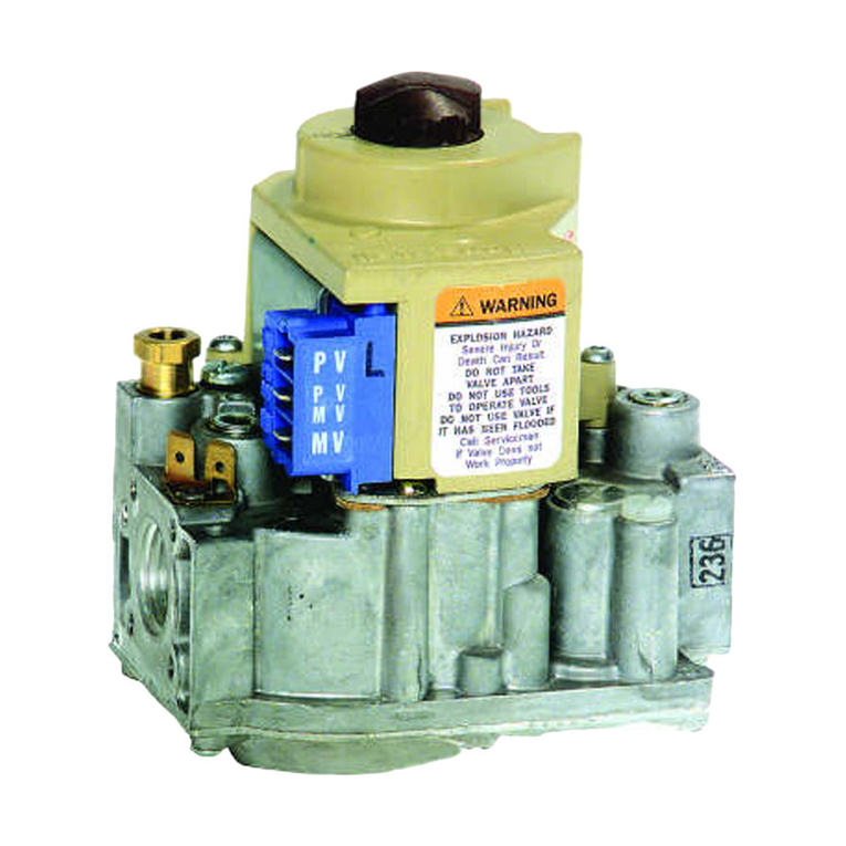
SV2 SERIES VALVES PREMIX ACCESSORIES
32-00180—01 2
–Protect pulse lines against damage and keep the lines free
from any contact to potential vibrating surfaces.
• In all cases, avoid creating a siphon-like shape.
• A wide variety of pulse line slopes and shapes may be
needed to fit into a particular appliance; best engineering
practice would be ‘1/2 bubble’ on a level (¼ inch of drop per
1 foot of run or about 6mm drop per 0.31m of run). However,
practical limitations may require some deviation from it.
Please consult Honeywell Thermal Solutions with your
particular geometrical arrangement if at doubt.
Fig. 1. V2MU mixing unit pulse line connections.
• (Refer to Fig. 1) To avoid condensate from back draft
entering any pulse line of the Fuel/Air Ratio Module,
downwards pointing pressure ports on the V2MU mixing
unit or any other device shall not be used.
• Partial blockage of the air intake of the V2MU mixing unit
can potentially influence the air pressure signal to the valve.
–Proper measures shall be taken to avoid the (partial) air
intake blockage of the V2MU mixing unit. Inspection
of the V2MU air intake shall be part of the annual
maintenance of the appliance.
Air Pre-Filter
The air pre-filter is included with every premix valve and is
available as a field replacement part as well. The air pre-
filter MUST be installed in every premix system, regardless
of whether the Heat Exchanger is used. The filter is designed
to remove fine dust particles from the air stream to the valve
FARMOD, which can collect at the internal FARMOD orifice
entrances, affecting flow resistance to the internal sensors
and eventually cause nuisance lockouts.
The filter must be mounted between the V2MU mixing unit
and the valve FARMOD in the air pulse line. When the Heat
Exchanger is used, it must also be mounted between the
V2MU mixing unit and the valve FARMOD, with the Heat
Exchanger first and the filter second.
IMPORTANT
• The filter should be mounted as close to the valve FARMOD
as possible.
• Replacement of the filter shall be included in the annual
appliance maintenance procedures.
Fig. 2. Pre-Filter installation.
Outdoor Air Installations
WARNING
Direct water ingress (e.g. from mist, rain or pressure
wash) into the pulse lines should be avoided or
prevented
IMPORTANT:
• When the valve is installed in an area with a temperature
continuously lower than the combustion air intake
temperature, a risk of condensate formation in the air pulse
line is present, which can affect the fuel/air ratio control,
depending on the appliance and permanently damage the
FARMOD and the system.
• In this case it is strongly recommended to install the
Honeywell SV2 Series HEATEXCHANGER-000 kit for a
complete condensation/dehumidification solution to avoid
permanent damage to the FARMOD and the system.
• When using the Honeywell HEATEXCHANGER-000 kit, the
valve + FARMOD may be installed above or below the mixing
unit + Heat Exchanger, but above is preferred.
• If the potential for condensation exists and the full
Honeywell dehumidification system is not used, Honeywell
cannot provide any guidance regarding the valve/FARMOD
position versus the mixing unit as this configuration has not
been designed or tested.
• To prevent condensation formation due to back draft, it is
recommended to purge the application after each burner
operation.
• If there is never a risk of condensation, meaning the ambient
room temperature is above the combustion air dew point at
all times, the SV2 Series Heat Exchanger kit is not needed.
In this case the valve + FARMOD can be mounted above or
below the mixing unit.
NOTE: The Heat Exchanger and the filter must be mounted
between the V2MU mixing unit and the FARMOD,
with the Heat Exchanger first and the filter mounted
as close to the FARMOD as possible
INSTALLATION SEQUENCE
WARNING
Explosion or Fire Hazard Can cause severe injury,
death, or property damage.
