manuals.online logo
Brands
  1. Home
  2. •
  3. Brands
  4. •
  5. Honeywell
  6. •
  7. Control Unit
  8. •
  9. Honeywell Fire-Lite Alarms CRF-300-6 User manual

Honeywell Fire-Lite Alarms CRF-300-6 User manual

F300-19-00 1 I56-1875-006
BEFORE INSTALLING
This information is included as a quick reference installation guide. Refer to
the appropriate Fire•Lite control panel installation manual for detailed sys-
tem information. If the modules will be installed in an existing operational
system, inform the operator and local authority that the system will be tempo-
rarily out of service. Disconnect the power to the control panel before install-
ing the modules. This system contains static sensitive components. Always
ground yourself with a proper wrist strap before handling any circuits so that
static charges are removed from the body. The module housing should also
be grounded.
NOTICE: This manual should be left with the owner/user of this equipment.
GENERAL DESCRIPTION
The CRF-300-6 Six Relay Control Module is intended for use in an intelligent
alarm system. Each module is intended for Form-C switching applications,
which do not require wiring supervision for the load circuit. A single isolated
set of dry relay contacts is provided for each module, which is capable of
being wired for either normally open or normally closed for each operation.
Each module has its own address. A pair of rotary code switches is used to set
the address of the first module from 01 to 154. The remaining modules are au-
tomatically assigned to the next five higher addresses. Provisions are included
for disabling a maximum of three unused modules to release the addresses to
be used elsewhere. Each CRF-300-6 module also has panel controlled green
LED indicators. The panel can cause the LEDs to blink, latch on, or latch off.
SPECIFICATIONS
Normal Operating Voltage: 15-32 VDC
Stand-By Current: 1.45 mA
Alarm Current: 32 mA (assumes all six relays have been switched once and all six LEDs solid on) Temperature Range:
32°F to 120°F (0°C to 49°C)
Humidity: 10 to 93% Non-condensing
Dimensions: 6.8˝H × 5.8˝W × 1.0˝D
Accessories: CH-6 Chassis; BB-6 Cabinet; BB-2 Cabinet
Wire Gauge: 12-18 AWG
Relay Current: 30 mA/Relay Pulse (15.6 mS pulse duration) pulse under panel control
CRF-300-6 Six Relay Control Module
Contents include:
(6) 1 × 3 Terminal Blocks
(1) 1 × 4 Terminal Blocks
(2) 11/4˝ Stand offs
(4) Machine Screws
(1) Shunt (NOTE: For the disable position, not more than one shunt shall be
installed at the same time)
(2) Nuts
COMPATIBILITY REQUIREMENTS
To ensure proper operation, this module shall be connected to a compat-
ible Fire•Lite system control panel (list available from Fire•Lite).
COMPONENTS
Following are descriptions of the CRF-300-6 mounting frameworks. There are
two mounting options for CRF-300-6 modules:
Up to six CRF-300-6 modules can be installed on a CH-6 in a BB-6 •
cabinet
One or two CRF-300-6 modules can be installed in a BB-2 cabinet•
WARNING
All relay switch contacts are shipped in the standby state (open) state, but
may have transferred to the activated (closed) state during shipping. To en-
sure that the switch contacts are in their correct state, modules must be made
to communicate with the panel before connecting circuits controlled by the
module.
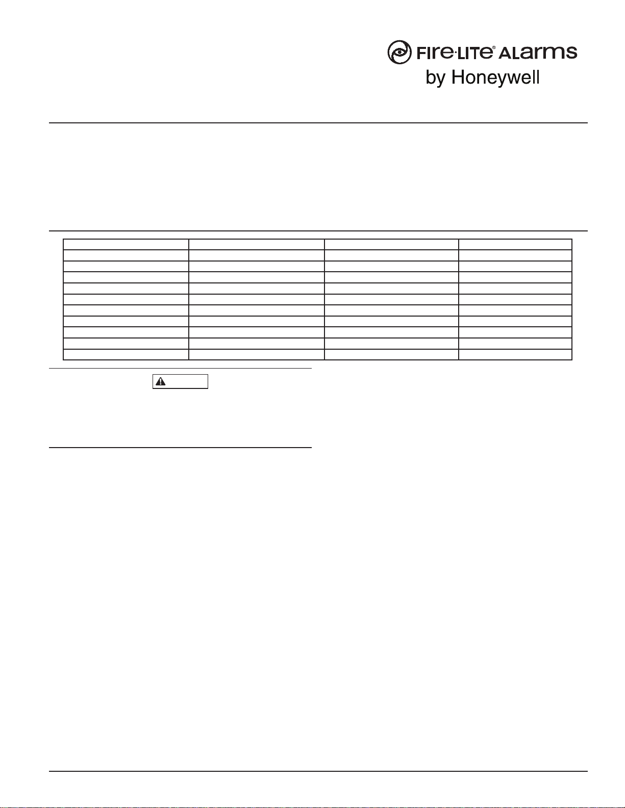
CURRENT RATING MAXIMUM VOLTAGE LOAD DESCRIPTION APPLICATION
3 A 30 VDC Resistive Non-coded
2 A 30 VDC Resistive Coded
.9 A 110 VDC Resistive Non-coded
.9 A 125 VDC Resistive Non-coded
.5 A 30 VDC Inductive (L/R=5ms) Coded
1 A 30 VDC Inductive (L/R=2ms) Coded
.3 A 125 VAC Inductive (PF=.35) Non-coded
1.5 A 25 VAC Inductive (PF = .35) Non-coded
.7 A 70.7 VAC Inductive (PF=.35) Non-coded
2 A 25 VAC Inductive (PF=.35) Non-coded
I56-1875-006
INSTALLATION AND MAINTENANCE INSTRUCTIONS
One FireLite Place
Northford, CT 06472
Phone: 203.484.7161
firealarmresources.com
INSTALLATION STEPS
1. Cabinet Mounting
FIGURE 3. TYPICAL MOUNTING HOLE LOCATIONS:
BACKBOX
MOUNTING
HOLES
In a clean, dry area, mount the backbox using the four holes provided in the
back surface of the cabinet.
2. Chassis Installation
The CH-6 chassis is mounted in the BB-6 cabinet. It is shipped with two self-
threading screws, which are used to fasten the chassis to the back wall of the
cabinet (see Figure 4).
FIGURE 4. MOUNTING THE CH-6 CHASSIS:
MOUNT WITH
SELF-THREADING SCREWS
TO BACK OF CABINET
The BB-2 cabinet comes with the chassis already installed, so no mounting
is necessary.
Chassis
The CH-6 chassis is used to mount CRF-300-6 modules in a BB-6 cabinet. It
accommodates up to six CRF-300-6 modules in a single cabinet row three
modules wide and two modules deep.
FIGURE 1. CH-6 CHASSIS:
The BB-2 cabinet has a built-in chassis that will accommodate one or two
CRF-300-6 modules.
FIGURE 2. BB-2 CABINET:
0
1
2
3
456789
0
78
6
5
4
3
21
910
11
12
13
14
15
BASE ADDRESS
ADDRESS
DISABLE
NONE
ONE
TWO
THREE
0
1
2
3
456789
0
78
6
5
4
3
21
910
11
12
13
14
15
BASE ADDRESS
ADDRESS
DISABLE
NONE
ONE
TWO
THREE
The front CRF-300-6 module positions of each chassis are offset below the rear
CRF-300-6 module positions so that all of the status indicators are visible.
Cabinets
A BB-6 cabinet will house the CH-6 chassis with up to six CRF-300-6 modules
installed on it. Refer to cabinet installation documents for dimensions.
The BB-2 cabinet houses one or two CRF-300-6 modules on the internal chas-
sis that is part of the cabinet. Refer to cabinet installation documents for
dimensions.
F300-19-00 2 I56-1875-006
C0206-00
C0234-00
C0235-00
C0236-00
firealarmresources.com
Step 2: Carefully swing the bottom edge of the board towards the back of
the board until it touches the short standoff attached to the chassis.
Step 3: Align the long standoff with the short standoff and tighten.
FIGURE 6B. INSTALLATION OF CRF-300-6 MODULE IN FRONT
CHASSIS POSITION:
2
1
3
Step 1: Insert the bottom edge of the CRF-300-6 module down into a front
slot of the chassis.
Step 2: Carefully swing the upper edge of the board towards the back of
the chassis until it touches the 11/4″ (31.75mm) standoffs installed
on the rear module.
Step 3: Align two 4-40 screws with the two standoffs and tighten.
Step 4: Address and wire the modules according to the instructions in this
manual.
WIRING
NOTE: All wiring must conform to applicable local codes, ordinances, and
regulations.
1. Install module wiring in accordance with the job drawings and appropri-
ate wiring diagrams.
2. Make electrical connections by stripping approximately 1/4˝ (6.35mm)
of insulation from the end of the wire sliding the bare end of the wire
under the clamping plate, and tightening the clamping plate screw.
3. Set the address on the modules per the job drawing. Use the rotary code
switches to set the address of the first module (between 01 and 154). The
remaining modules are automatically assigned to the next five higher
addresses. For example, if the base address switch is set to 28, the next
five modules will be addressed to 29, 30, 31, 32, and 33. DO NOT set
the lowest address above 154, as the other modules will be assigned to
nonexistent addresses.
NOTE: Some panels support extended addressing. In order to set the module
above address 99 on compatible systems, carefully remove the stop on the up-
per rotary switch. If the panel does not support extended addressing, do not
set the lowest address above 94.
4. A shunt is provided to disable a maximum of three unused modules.
Modules are disabled from the highest address and work downward. If
two modules are disabled, the lowest four addresses will be functional,
while the highest two will be disabled. For example, if the shunt for Ad-
dress Disable is placed on “two” and the base address switch is set to 28,
the modules will be assigned to 28, 29, 30 and 31.
NOTE: Power must not be applied to the unit when changing functionality of
the shunts.
F300-19-00 3 I56-1875-006
3. Module Installation
There are two methods for installing a module in the rear position of a chas-
sis. Method one is for installation of a rear module only, when no module will
be installed in front of it. Refer to Figure 5 for instructions. Method two is for
installation of a rear module when another module will be installed in the
chassis position in front of it. Refer to Figures 6a and 6b for method two. All
necessary screws and standoffs are supplied with the modules.
FIGURE 5. INSTALLATION OF REAR MODULE ONLY, METHOD ONE:
2
1
3
Step 1: Insert the bottom of the CRF-300-6 module down into a rear slot on
the chassis.
Step 2: Carefully swing the upper edge of the board back towards the back
of the chassis until it touches the two standoffs.
Step 3: Align two 4-40 screws with the two standoffs and tighten.
Step 4: Address and wire the modules according to the instructions in this
manual.
The steps in Figures 6a and 6b describe and illustrate module installation
when the rear chassis position and the position in front of it will be filled.
Front position installation is possible only if the rear position is filled with a
module.
FIGURE 6A. INSTALLATION OF CRF-300-6 MODULE IN A REAR
CHASSIS POSITION, METHOD TWO:
1
Step 1: Insert the bottom edge of the CRF-300-6 module down into a rear
slot of the chassis.
C0243-00
C0245-00
C0244-00
firealarmresources.com
F300-19-00 4 I56-1875-006
©2008 Fire•Lite Alarms, Inc.
This device complies with part 15 of the FCC Rules. Operation is subject to the fol-
lowing two conditions: (1) This device may not cause harmful interference, and (2)
this device must accept any interference received, including interference that may
cause undesired operation.
NOTE: This equipment has been tested and found to comply with the limits for a
Class B digital device, pursuant to Part 15 of the FCC Rules. These limits are designed
to provide reasonable protection against harmful interference in a residential instal-
lation. This equipment generates, uses and can radiate radio frequency energy and,
if not installed and used in accordance with the instructions, may cause harmful
interference to radio communications. However, there is no guarantee that interfer-
NOTES:
The relay contacts on the CRF-300-6 may be connected to either a •
power-limited or non power-limited source, this wiring must remain
separated by at least 1/4˝ (6.35 mm) from all power-limited wiring.
Power-limited circuits must employ type FPL, FPLR, or FPLP cable as •
required by Article 760 of the NEC.
For easier wiring, assign all power-limited wiring to one side rather than • alternating with non power-limited.
PROGRAMMING
The CRF-300-6 module operates with the following Fire Alarm Control Panels:
MS-9200•
MS-9600•
0
1
2
3
4
56789
0
78
6
5
4
3
2
1
910
1 1
12
13
14
15
N.C.
N.O.
COMMON
ADDRESS 5
N.C.
N.O.
COMMON
ADDRESS 4
N.C.
N.O.
COMMON
ADDRESS 3
N.C.
N.O.
COMMON
ADDRESS 2
N.C.
N.O.
COMMON
ADDRESS 1
N.C.
N.O.
COMMON
ADDRESS 0
– + – +
SLC
BASE ADDRESS
ADDRESS
DISABLE
NONE
ONE
TWO
THREE
6.8"
5.8"
FROM PANEL
OR PREVIOUS DEVICE
SIGNAL LINE CIRCUIT
32 VDC MAX.
TWISTED PAIR IS RECOMMENDED
TO NEXT
DEVICE
–+
–
+
–
+
NC
NO
COMMON
RELAY CONNECTIONS
ST A TUS
INDICATORS
FIGURE 7. WIRING AND PROGRAMMING THE CRF-300-6 MODULE:
C0778-02
FCC STATEMENT
ence will not occur in a particular installation. If this equipment does cause harmful
interference to radio or television reception, which can be determined by turning the
equipment off and on, the user is encouraged to try to correct the interference by one
or more of the following measures:
– Reorient or relocate the receiving antenna.
– Increase the separation between the equipment and receiver.
– Connect the equipment into an outlet on a circuit different from that to
which the receiver is connected.
– Consult the dealer or an experienced radio/TV technician for help.
firealarmresources.com

Other Honeywell Control Unit manuals

Honeywell S7800A User manual

Honeywell

Honeywell S7800A User manual

Honeywell W6215 Series Operation manual

Honeywell

Honeywell W6215 Series Operation manual

Honeywell PRO4200 User manual

Honeywell

Honeywell PRO4200 User manual

Honeywell SK-Mon-10 User manual

Honeywell

Honeywell SK-Mon-10 User manual

Honeywell VS8420C User manual

Honeywell

Honeywell VS8420C User manual

Honeywell RV260 Series User manual

Honeywell

Honeywell RV260 Series User manual

Honeywell DirectLine DL423 User manual

Honeywell

Honeywell DirectLine DL423 User manual

Honeywell Kromschroder GIK Series User manual

Honeywell

Honeywell Kromschroder GIK Series User manual

Honeywell V5013N Operation manual

Honeywell

Honeywell V5013N Operation manual

Honeywell A4021 Series User manual

Honeywell

Honeywell A4021 Series User manual

Honeywell SLATE User manual

Honeywell

Honeywell SLATE User manual

Honeywell MDC108200 User manual

Honeywell

Honeywell MDC108200 User manual

Honeywell Aquastat L4006 User manual

Honeywell

Honeywell Aquastat L4006 User manual

Honeywell MasterLogic 50 Series User manual

Honeywell

Honeywell MasterLogic 50 Series User manual

Honeywell 7800 SERIES User manual

Honeywell

Honeywell 7800 SERIES User manual

Honeywell Hometronic HB 05 User manual

Honeywell

Honeywell Hometronic HB 05 User manual

Honeywell S8910U Original instructions

Honeywell

Honeywell S8910U Original instructions

Honeywell RM7800L1087 User manual

Honeywell

Honeywell RM7800L1087 User manual

Honeywell V4730C User manual

Honeywell

Honeywell V4730C User manual

Honeywell VISTA User manual

Honeywell

Honeywell VISTA User manual

Honeywell CentraLine CLIOL822A Operation manual

Honeywell

Honeywell CentraLine CLIOL822A Operation manual

Honeywell VR8405 User manual

Honeywell

Honeywell VR8405 User manual

Honeywell SILENT KNIGHT Farenhyt Series User manual

Honeywell

Honeywell SILENT KNIGHT Farenhyt Series User manual

Honeywell TrueZONE ARD Series User manual

Honeywell

Honeywell TrueZONE ARD Series User manual

Popular Control Unit manuals by other brands

Harman AMX HPX-AV102-MDP-R quick start guide

Harman

Harman AMX HPX-AV102-MDP-R quick start guide

Inel ST-01R Instructions for installation and use

Inel

Inel ST-01R Instructions for installation and use

Singer Valve 106-SC Installation, operating and maintenance instructions

Singer Valve

Singer Valve 106-SC Installation, operating and maintenance instructions

Sollae Systems CSW-M85 user manual

Sollae Systems

Sollae Systems CSW-M85 user manual

Sonance VC60S installation instructions

Sonance

Sonance VC60S installation instructions

RS S81 quick start guide

RS

RS S81 quick start guide

Sony IFU-WLM3 operating instructions

Sony

Sony IFU-WLM3 operating instructions

Leviton MC 7516 user guide

Leviton

Leviton MC 7516 user guide

Anval SG Series Installation & maintenance manual

Anval

Anval SG Series Installation & maintenance manual

Notifier FDM-1 Installation and maintenance instructions

Notifier

Notifier FDM-1 Installation and maintenance instructions

Data Video CCU-200 instruction manual

Data Video

Data Video CCU-200 instruction manual

WAGO 750-532 manual

WAGO

WAGO 750-532 manual

Toshiba IK-HR1CD instruction manual

Toshiba

Toshiba IK-HR1CD instruction manual

SMC Networks VKF300 Series Installation and maintenance manual

SMC Networks

SMC Networks VKF300 Series Installation and maintenance manual

GRASS VALLEY KAMELEON Series instruction manual

GRASS VALLEY

GRASS VALLEY KAMELEON Series instruction manual

Halemeier AppMitter installation instructions

Halemeier

Halemeier AppMitter installation instructions

SMC Corporation EX250-SCN1 Technical specification

SMC Corporation

SMC Corporation EX250-SCN1 Technical specification

IBA ibaMS16xAO-10V/-20mA manual

IBA

IBA ibaMS16xAO-10V/-20mA manual

manuals.online logo
manuals.online logoBrands
  • About & Mission
  • Contact us
  • Privacy Policy
  • Terms and Conditions

Copyright 2025 Manuals.Online. All Rights Reserved.