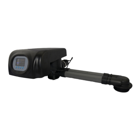
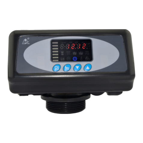
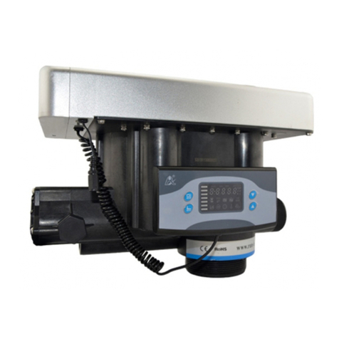
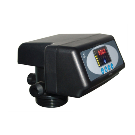
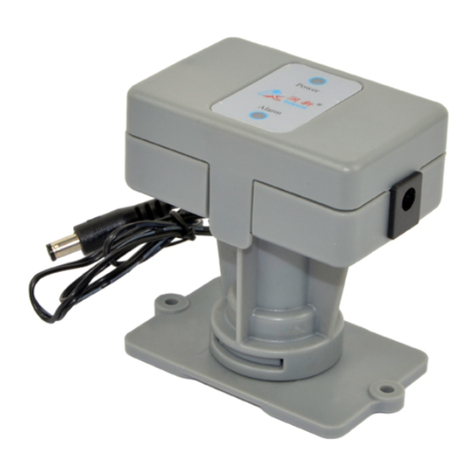
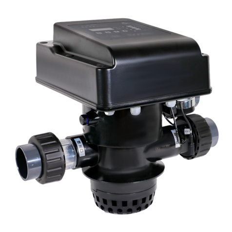
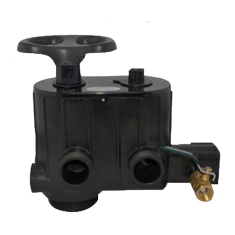
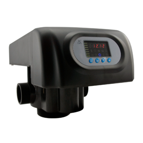
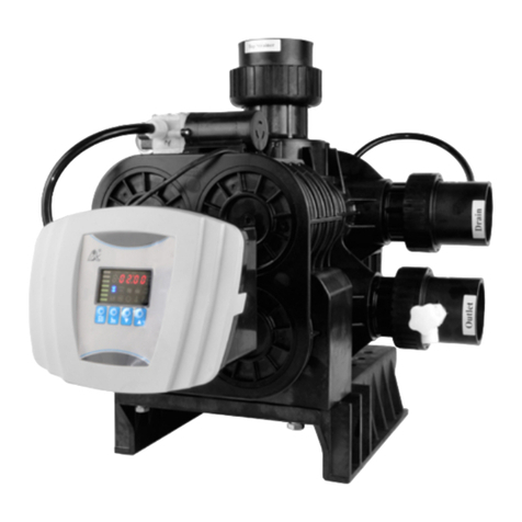
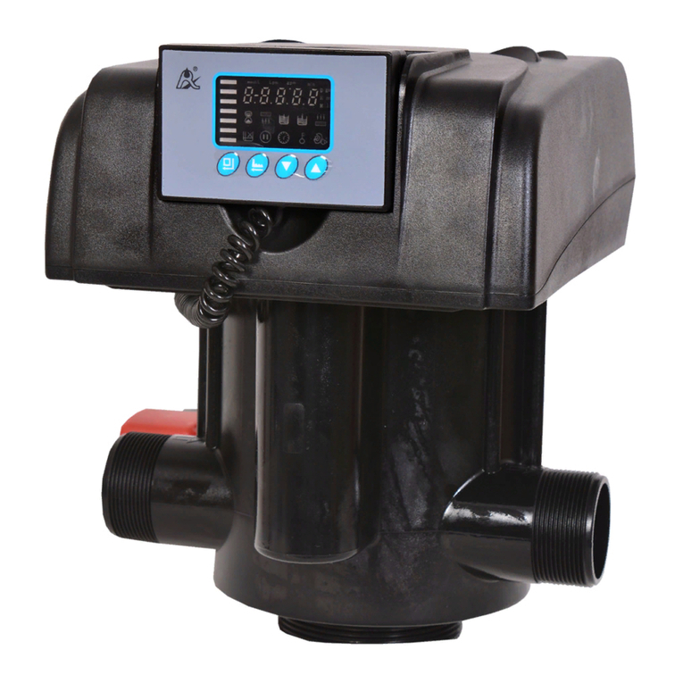
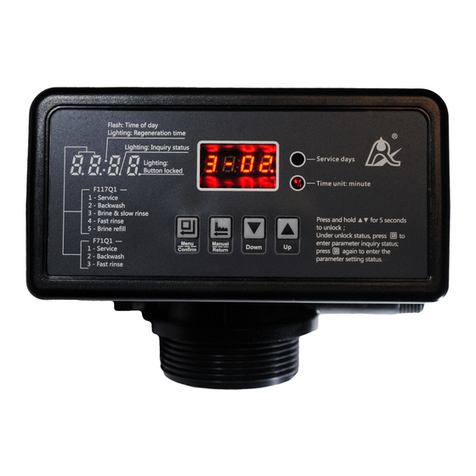
Runxin 73605 User manual

Multi-functional Flow Control Valve for
Water Treatment Systems
73605(Old Model No.:F92A)
73605B(Old Model No.:F92B )
73605/41206L(Old Model No.:F92A/F70EL)
73605B/41206L(Old Model No.:F92B/F70EL)
Instruction Manual
Please read this manual in details before using the valve and
keep it properly in order to consult in the future. 0WRX.466.043
International Patent No.:WO 2006/007772
China Patent No:ZL02220153.X,
ZL200420078956.5
American Patent No.:7549446
Indian Patent No.:232582
Russian Patent No.:2349819
South Korea Patent No.:10-0914137
Mexico Patent No.:268581
Australian Patent No.:2005263257
Philippine Patent No.:1-2006-502553
Taiwan Patent No.:M287896

MODEL73605 73605B 73605/41206L 73605B/41206L
Before the valve put into use, please fill in the below content so as to
help us to refer in the future.
Softener System Configuration
Tank Size:Dia. mm,Height mm;
Resin volume L;Brine Tank Capacity L;
Hardness of Raw water mmol/L;
Pressure of Inlet Water MPa;
Control Valve Model ;Number ;
The Specification of Drain Line Flow Control ;
Injector No. .
Water Source: Ground-water□ Filtered Ground-water □Tap water □
Other .
Parameter Set
Parameter
Unit
Factory Default
Actual
Value
On-line Program
/
C-01(Interlock
Program)
Data Clear
/
d-01(Close)
Control Mode
A-01/02/03/04/05/06
/
A-01
Water Treatment
Capacity(A-01/02/03/04/05)
m3
50.00 m3
Regeneration Start-up Time
(A-01/03/05)
/
02∶00
Operation Days(A-06)
D.
03
Regeneration Index (A-03/04)
/
0.65
Resin Volume (A-03/04)
L.
20
Raw Water Hardness(A-03/04)
mmol/
L
1.2

MODEL73605 73605B 73605/41206L 73605B/41206L
Backwash Interval Times
/
F-00
Backwash Time
min:se
c
10:00
Brine & Slow Rinse Time
min:se
c
60:00
Fast Rinse Time
min:se
c
10:00
Brine Tank Refill Time
min:se
c
05:00
Interval Regeneration Days
D.
30
Output Mode b-01(02)
/
b-01
If there is no special requirement when product purchase, we choose
8468062 drain line flow control and 8468055 brine line flow control, 6309
injector for the standard configuration.

MODEL73605 73605B 73605/41206L 72605B/41206L
I
Catalogue
Notice .........................................................................................................3
1. Product Overview...................................................................................4
1.1. Main Application & Applicability ………………………………4
1.2. Product Characteristics……………………………………. 4
1.3. Service Condition…………………………………………..6
1.4. Product Structure and Technical Parameters………………….7
1.5. Installation…………………………………………………….8
2. Basic Setting & Usage .........................................................................10
2.1. The Function of PC Board……………………………………10
2.2. Basic Setting & Usage………………………………………11
3. Application..........................................Hiba! A könyvjelző nem létezik.
3.1. Softener Flow Chart……………………………………………
Hiba! A könyvjelző nem létezik.
3.2. The Function and Connection of PC Board…………………16
A. Signal Output.........................................................................17
B. Interlock.................................................................................20
C. One in Service One Standby.................................................20
D. Remote Handling Input.........................................................21
E. Interlock System....................................................................21
F. Series System........................................................................21
3.3. System Configuration and Flow Rate Curve ………………….22
3.4. Parameter Settlement………………………………………… 24
3.5. Parameter Enquiry and Setting……………………………..25
3.6. Trial Running…………………………………………………29
3.7. Trouble-Shooting ………………………………………………..31
3.8. Spare Part and Part No………………………………………..35
4. Warranty Card......................................................................................41

MODEL73605 73605B 73605/41206L 72605B/41206L
1
Notice
To ensure normal operation of the valve, please consult with
professional installation or repairing personnel before use it.
If there are any of pipeline engineering and electric works, there must
be finished by professional at the time of installation.
Do not use the control valve with the water that is unsafe or unknown
quality.
Depending on the changing of working environment and water
requirement, each parameter of softener should be adjusted accordingly.
When the water treatment capacity is too low, please check the resin. If
the reason is shortage of resin, please add; if the resin is turn to
reddish brown or broken, please replace.
Test water periodically to verify that system is performing satisfactorily.
Sodium used in the water softening process should be considered as
part your overall dietary salt intake. Contact doctor if you are on a low
sodium diet.
Ensure that there is solid salt all the time in the brine tank in the course
of using, when this valve is used for softening. The brine tank should be
added the clean water softening salts only, at least 99.5% pure,
forbidding use the small salt.
Do not put the valve near the hot resource, high humidity, corrosive,
intense magnetic field or intense librations environment. And do not
leave it outside.
Forbidden to carry the injector body. Avoid using injector body as
support to carry the system.
Forbidden to use the brine tube or other connectors as support to carry
the system.
Please use this product under the water temperature between 5~

MODEL73605 73605B 73605/41206L 73605B/41206L
2
50℃,water pressure 0.15~0.6MPa. Failure to use this product under
such conditions voids the warranty.
If the water pressure exceeds 0.6Mpa, a pressure reducing valve must
be installed before the water inlet. While, if the water pressure under
0.15MPa, a booster pump must be installed before the water inlet.
It is suggested to install PPR pipe, corrugated pipe or UPVC pipe,
instead of TTLSG pipe.
Do not let children touch or play, because carelessness operating may
cause the procedure changed.
When the attached cables of this product and transformer are changed,
they must be changed to the one that is from our factory.

MODEL73605 73605B 73605/41206L 73605B/41206L
3
1.Product Overview
1.1.Main Application & Applicability
Used for softening or demineralization water treatment systems
Be suitable for
Residential softening system
Ion exchange equipment
Boiler softening water system
RO pretreatment softening system, etc.
1.2.Product Characteristics
Simple structure and reliable sealing
It adopts hermetic head faces with high degree pottery and
corrosion resistance for opening and closing. It combines with Service,
Backwash, Brine & Slow Rinse, Brine Refill and Fast Rinse.
Up-flow Regeneration
Up-flow regeneration, salt and water savings. No hard water pass
and hard water pass options.
Soft Water Refill
System also in service when in brine tank refill (Means soft water
flows in outlet), save the regeneration time and regenerate more
efficient.
Big Water Flow Rate
Flow Rate will be not lower 4.7m3/h when pressure drop is 0.1MPa.
Historical Record can be Enquired
Can enquiry soft edition, maximum flow rate after being used, totally
using days, regeneration times after being used and all data records can
be clear.
Manual function

MODEL73605 73605B 73605/41206L 73605B/41206L
4
Realize regeneration immediately by pushing manual button at
any time.
Long outage indicator
If outage overrides 3days, the time of day indicator 12:12 will flash to
remind people to reset new time of day. The other set parameters do not
need to reset. The process will continue to work after power on.
Buttons lock
No operations to buttons on the controller within 1 minute, button
lock indicator light on which represent buttons are locked. Before
operation press and hold the and buttons for 3 seconds to unlock.
This function can avoid incorrect operation.
Technicist or manufacturers can choose regeneration control
mode via getting authority
When control valve get connected with power, press button ,
and orderly to enter into enquiry and set menu which is available for
technicist or manufacture. Six control mode listed in table one can be
chose in regeneration control mode menu.
Mode
Name
Instruction
A-01
Meter
Delayed
Regenerate on the day although the available
volume of treated water drops to zero (0).
Regeneration starts at the regeneration time.
A-02
Meter
Immediate
Regenerate immediately when the available
volume of treated water drops to zero(0).
A-03
Intelligent
Meter
Delayed
Meter Delayed Regeneration type, but by setting
Resin Volume, Feed Water Hardness,
Regeneration Factor, the controller will calculate
the System Capacity.
A-04
Intelligent
Meter
Immediate
Meter Immediately Regeneration Type, but by
setting Resin Volume, Feed Water Hardness,
Regeneration Factor, the controller will calculate
the System Capacity.
A-05
Surplus
When the available volume of treated water not

MODEL73605 73605B 73605/41206L 73605B/41206L
5
Signal output
There is a signal output connector on main control board. It is for
controlling external wiring. (Refer to Figure7to Figure 13).
There are two kinds of output modes. b-01 Mode: Turn on start of
regeneration and shut off end of regeneration; b-02 Mode: Signal
available only intervals of regeneration cycles(Motor running
moment).(Regeneration sequence 1 as example), show as following:
Interlock function
Set program function of “Interlock c-01” to realize only one valve in
regeneration but the other valves are in service while several valves
parallel or series connection in system. (Application refer to Figure 14)
One in service one standby
Set program function of “One in service one standby” to realize
continuously water supply while the outlet of two valves connected with
Runxin specialized tee valve, this is called one in service one standby.
(Application refer to Figure 15)
Remote Handling Connector
This connector can receive 5~24VDC external signal, used together
Water
Comparing
more than average day water capacity of
previous 7 days, regeneration starts at the
regeneration time.
A-06
Time Type by
Day
Service days count down to zero(0),regeneration
stars at the regeneration time.

MODEL73605 73605B 73605/41206L 73605B/41206L
6
with PLC, and computer etc. to control the valve remotely. (Application
refer to Figure 16)
Maximum interval regeneration days (Not available for A-06)
Under the situation of service reaching the setting days and the
volume not yet, it could enter into regeneration process forcibly when
current time is the same as regeneration time.
All parameters can be modified
According to the water quality and usage, the parameters in the
process can be adjusted.
1.3.Using condition
Valve should be used under the below conditions
Item
Requirement
Working
conditions
Working
pressure
0.15MPa~0.6MPa
Water
temperature
5℃~50℃
Working
environment
Environment
temperature
5℃~50℃
Relative
humidity
≤95%(25℃)
Electrical
Facility
AC100~240V/50~60Hz
Inlet water
quality
Water turbidity
Up-flow regeneration<2FTU
Water hardness
First Grade Na+<6.5mmol/L;Second
Grade Na+<10mmol/L
Free chlorine
<0.1mg/L
Iron2+
<0.3mg/L
CODMn
<2mg/L(O2)
In the above table, First Grade Na+ represents First Grade Na+
Exchanger. Second Grade Na+ represents Second Grade Na+
Exchanger.
When the water turbidity exceeds the conditions, a filter should be
installed on the inlet of control valve.

MODEL73605 73605B 73605/41206L 73605B/41206L
7
When the water hardness exceeds the conditions, the outlet water
hardness will hardly reach the requirement of boiler feed water(0.03
mmol/L). It is suggested to adopt second grade softener.

MODEL73605 73605B 73605/41206L 73605B/41206L
8
1.4.Product Structure and Technical Parameters
The appearance is just for reference.
It is subjected to the real product.
Connect Port Dimensions
Product Model
Bypass or Flow
Meter
Inlet
Port
Outlet
Port
Drain
Port
Brine
Port
Base
Riser Pipe
Hard
Water
Bypass
73605
Flow Meter
5447007
G1’’
G1’’
NPT3/4’’
G3/8’’
2.5”-8NPS
M
1″D-GB(Ø32)
No
73605B
Flow Meter
5447007
G1’’
G1’’
NPT3/4’’
G3/8’’
2.5”-8NPS
M
1″D- GB(Ø32)
Yes
73605/41602L
Bypass 41602L
NPT1’’
NPT1’’
NPT3/4’’
G3/8’’
2.5”-8NPS
M
1″D-GB(Ø32)
No

MODEL73605 73605B 73605/41206L 73605B/41206L
9
1.5.Installation
A. Installation notice
Before installation, read all those instructions completely. Then
obtain all materials and tools needed for installation.
The installation of product, pipes and circuits, should be
accomplished by professional to ensure the product can operate
normally.
Perform installation according to the relative pipeline regulations
and the specification of Water Inlet, Water Outlet, Drain Outlet, and Brine
Line Connector.
73605B/41602L
Bypass 41602L
NPT1’’
NPT1’’
NPT3/4’’
G3/8
2.5”-8NPS
M
1″D- GB(Ø32)
Yes
Main Technical Parameters
Water Capacity
m3/h
4.7(0.1Mpa Pressure Drop)
Power Input
AC100~240V/50~60Hz
Power Output
DC12V,2.0A
Regeneration
Mode
A-01 Meter Delay: Regeneration happens when the capacity reaches
to zero and the preset time of regeneration is reached.
A-02 Meter Immediate: Regeneration happens when the capacity
reaches to zero.
A-03 Intelligent Meter Delay: The same delay function as A-01 but the
capacity is set by input of the Resin Volume and Feed Water Hardness.
The control valve calculates the gallons before regeneration.
A-04 Intelligent Meter Immediate: The same delay function as A-02 but
the capacity is set by inputting the Resin Volume and Feed Water
Hardness. The Control valve calculates the gallons before
regeneration.
A-05 Surplus Water Comparing: When the surplus water capacity less
than previous 7 days daily using, and current time reaches to preset
time of regeneration, regenerate happens.
A-06 Time type by day: Service days count down to zero (0),
regeneration stars at the regeneration time.

MODEL73605 73605B 73605/41206L 73605B/41206L
10
B. Device location
①The filter or softener should be located close to drain.
②Ensure the unit is installed in enough space for operating and
maintenance.
③Brine tank need to be close to softener.
④The unit should be kept away the heater, and not be exposed outdoor.
Sunshine or rain will cause the system damage.
⑤Please avoid to install the system in one Acid/Alkaline, Magnetic or
strong vibration circumstance, because above factors will cause the
system disorder.
⑥Do not install the filter or softener, drain pipeline in circumstance which
temperature may drop below 5℃, or above 50℃.
⑦One place is recommended to install the system which causes the
minimum loss in case of water leaking.
C. Pipeline installation
①Install control valve
a.As the Figure 1-1 shows, select the riser pipe with 32mm OD, glue the
riser pipe to the bottom strainer and put it into the mineral tank, cut off
the exceeding tube out of tank top opening. Plug the riser tube in case of
mineral entering

MODEL73605 73605B 73605/41206L 73605B/41206L
11
Fill the mineral to the tank, and the height is accordance with the design
code.
b. Install the top distributor to the valve.
c. Insert the riser tube into control valve and screw tight control valve.
Note:
●The length of riser tube should not be lower 15mm than tank top
opening height, lower than 8mm is advisable, and its top end should be
rounded to avoid damage of O-ring inside the valve.
●Avoid floccules substance together with resin to be filled in the mineral
tank.
●Avoid O-ring inside control valve falling out while rotating it on the tank.
②Install bypass valve
As figure 2 shows, put the sealing ring into nut of animated
connector, and screw in water inlet and outlet.
Insert animated connector to bypass valve then insert in buckle.
Figure 2
③Pipeline connection
As figure 3shows, inlet pipe connect with inlet connector of bypass
via 1” NPT female connector. Outlet pipe connect
with outlet pipe of bypass via 1” NPT female connector.

MODEL73605 73605B 73605/41206L 73605B/41206L
12
④Install drain pipeline
a. As the Figure 4 shows, Insert drain line flow control into drain outlet.
b. Insert O-ring into O-ring slot of drain connector.
c. Insert drain hose connector into drain outlet.
d. Screw drain hose connector into drain outlet, and lock it.
e. Locate the drain hose well as the Figure4 show.
Notice
●Drain line pipe lower than valve is advisable, if the drain line pipe higher
2m than valve is permitted, and the pipe should not longer then 3m. Pipe
too high or too long both will impact brine.

MODEL73605 73605B 73605/41206L 73605B/41206L
13
●Be sure not connect drain with sewer, and leave a certain space
between them, avoid wastewater be absorbing to the water treatment
equipment, such as showed in the Figure4.
⑤Connect brine tube
a. As Figure5 shows, slide 3/8″brine tube hose connector over end of
brine tube.
b. Insert the filter net into the tube.
c. Insert tube bushing into the end of brine tube.
d. Tighten brine draw hose connector onto brine line connector.
e.Connect the other end of brine tube with the brine tank. (the liquid level
controller and air-blocker should be installed in the brine tank.)
Remark: The brine tube and drain pipeline should not be bended or
plugged.
2. Basic Setting & Usage

MODEL73605 73605B 73605/41206L 73605B/41206L
14
2.1. The Function of PC Board
A. Time of day indicator
lights on, the data indicates current time.
B. Button lock indicator
Lights on, indicate the buttons are locked.At this moment, press any
single button will not work (No operation in one minute, will light on
and lock the buttons.)
Solution:Press and hold both and for 3 seconds until the
lights off.
C. Program Mode indicator
lights on, indicate the enquiry status, press or can enquiry all
parameters.
flashes, indicate the setting status, press or could change
all parameters.
D. Manu/Confirm button
Press , light on, enter program display mode and use or to
view all values.
In program display mode, press , flashes, enter program set

MODEL73605 73605B 73605/41206L 73605B/41206L
15
mode, press or and adjust values.
Press after all program are set, and then the voice “Di” means all
setting are success and return program display mode.
E. Manual/Return button
Press in any status, it can proceed to next step.(Example: Press
in Service status, it will start regeneration cycles instantly; Press
while it is in Backwash status, it will end backwash and go to
Brine &Slow Rinse at once.)
Press in program display mode, and it will return in Service; Press
in program set mode, and it will return program display mode.
Press while adjusting the value, then it will return program display
mode directly without saving value.
F.Down▼ and Up▲
In menu mode, press ▲or▼ to page up or page down all setting
entries.
In program set mode, press ▲or▼ to adjust values.
Press and hold both ▲and ▼for 3 seconds to lift the Button Lock
status.
Press when in parameter setting status or historical data record
enquiry status can back to enquiry status, then press again can
back to working status.
Press when in change parameters status, all the changes will not
be saved and program back to enquiry status.
2.2. Basic Setting & Usage
A. Parameter specification available to terminal user
Function
Indicate
Factory
Default
Parameter
set range
Instruction
Time of day
Rando
m
00:00~23:59
Set the time to be current time, 24
hours type

MODEL73605 73605B 73605/41206L 73605B/41206L
16
Water
Treatment
Capacity
50m3
0~999.99 m3
Water Treatment Capacity for one
operation cycle (m3)
Regenerati
on Time
02:00
02:00
00:00~23:59
Time when regenerate happens,
Exchange
Factor
AL.65
0.65
0.30~0.99
Matter with raw water hardness, the
higher the hardness is, the lower of
exchange factor
Resin Volume
20L
20L
5~500L
Resin volume in tank (L)
Raw Water
Hardness
Yd1.2
1.2
0.1~9.9
Inlet water hardness (mmol/L)
Interval
Backwash
Times
F-00
F-00
0~20
Whether need backwash in every
operation cycle
Backwash
10:00
0~99:59
Backwash Time (Min :Second)
Brine & Slow
rinse
60:00
0~99:59
Brine & Slow rines time (Min :Second)
Fast rinse
10:00
0~99:59
Fast rinse time (Min :Second)
Brine Refill
05:00
0~99:59
Brine refill time (Min :Second)
Service Days
1-03D
0~99 天
Only available for time type by day
Maximum
Interval
Regeneration
Days
H-30
30
0~40
Regenerate on the day even
through the available volume of
treated water does not drop to
zero (Available for
A-01/02/03/04/05 ).
Enq
uiry
Hist
oric
al
Rec
ord
Maximu
m flow
rate in
previous
seven
days
x.xx
m3/h
/
/
Enquiry the maximum flow rate in
previous seven days
Regener
ated
times
xx
/
/
Enquiry the automatic regenerated
times (Manual regeneration only
include)
Signal
Output Mode
b-01
01
01 or 02
Signal output in the regeneration
process (See P3)
This manual suits for next models
7
Table of contents
Other Runxin Control Unit manuals

Runxin
Runxin 51240B (F112BS) User manual

Runxin
Runxin F104 A User manual

Runxin
Runxin F79A-LCD User manual

Runxin
Runxin 63510 User manual

Runxin
Runxin 53515 User manual

Runxin
Runxin F71B1 User manual

Runxin
Runxin 63504 User manual
Runxin
Runxin 63518 User manual

Runxin
Runxin F56A User manual
Runxin
Runxin 53520 User manual
Popular Control Unit manuals by other brands

Keyautomation
Keyautomation CT102 24 Instructions and warnings for installation and use

SIGMA TEK
SIGMA TEK DIAS-Drive 2000 operating manual

Paradox
Paradox IP150+ installation manual

FRONIUS
FRONIUS String Control 250/25 operating instructions

B meters
B meters IWM-MB4 manual

mr. steam
mr. steam iSteam 2.0 Control Installation, operation & maintenance manual