manuals.online logo
Brands
  1. Home
  2. •
  3. Brands
  4. •
  5. Honeywell
  6. •
  7. Controllers
  8. •
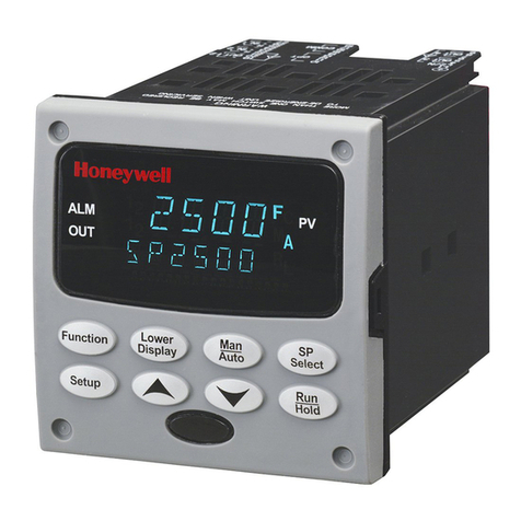
  9. Honeywell UDC2500 User manual

Honeywell UDC2500 User manual

January 2017 51-52-33-137 1
Replacement Printed Wiring Boards
Instruction Sheet for UDC2500 and UDC3200
Universal Digital Controllers
Document No: 51-52-33-137
Effective Date: January 2017
Supersedes: March 2010
Kit Contents:
This kit contains one of the following replacement Printed Wiring Boards:
UDC2500 MCU/Input Board –Part No. 51452801-503
UDC2500 Limit Controller MCU/Input Board –Part No. 51452801-504
UDC2500 Display/Keyboard –Part No. 51452758-501
UDC3200 MCU/Input Board –Part No. 51452819-501
UDC3200 Display/Keyboard –Part No. 51452845-501
UDC3200 Optional Input Board –Part No. 51452825-501
UDC2500/3200 Power 90-264Vac Board –Part No. 51452822-502
UDC2500/3200 Power 24Vac/dc Board –Part No. 51452822-503
UDC2500/3200 Aux Out/Dig Inp/RS-485 –Part No. 51452809-501
UDC2500/3200 Aux Out/Dig Inp/RS-485 –Part No. 51452810-501
UDC2500/3200 Aux Out/Dig Inp/Ethernet–Part No. 51452816-501
UDC2500/3200 Current Output Board –Part No. 51452804-501
UDC2500/3200 Dual Relay Board –Part No. 51452807-501
UDC Controller Keypad Button Guide Kit –Part No. 50133058-501
Equipment needed:
Small flat-bladed screwdriver
Small needle-nose pliers
January 2017 51-52-33-137 2
Procedures:
The procedure tables that follow list the steps required to replace the old Printed Wiring Board in
your controller with the one supplied in this kit.
Table 1: How to Remove the Chassis
Step
Action
1
Remove any screws in the front face.
2
Insert a flat-bladed screwdriver into the tabs of the case as shown in
Figure 1 and pry chassis forward slightly until the chassis connectors
separate from the back of the case.
3
Grasp the bezel and pull the chassis out of the case.
Figure 1: Chassis Removal
Using a thin screwdriver, gently pry the side tabs from the front face and twist the screwdriver
slightly to disengage the front. Pry just enough to release it, otherwise you’ll bend or break
the tab. If you break or bend the tab and can’t reattach the front securely, you’ll need to reattach
the front using the 4 NEMA4 screws provided.
Insert thin screwdriver under
tabs and gently pry the tab and
twist slightly to disengage front.
January 2017 51-52-33-137 3
Table 2: Board Identification
Step
Action
1
Note the location of the various boards inside the instrument.
2
Match up the replacement board in this kit with the one inside the
instrument so that you become familiar with where it goes.
Figure 2: Board Identification
Power / Output Bd.
Auxiliary Output / Digital Input /
Communication Bd.
MCU / Inputs / Output Bd.
Output Bd.
Option Input Bd.
Display/Keyboard
Wires on J8
January 2017 51-52-33-137 4
Table 3: How to Remove the Printed Wiring Boards from the Chassis
Step
Action
1
Remove the chassis from the case as shown in Figure 1.
2
Find J8 in Figure 2. Remove all wire connectors from J8 by sliding a small screwdriver
under each connector and lift the release.
3
Separate the chassis frame at the release points shown in Figure 3 and ease each
printed wiring board out of its socket on the display/keyboard assembly. Pull all boards
out of the chassis.
4
Lay the boards flat on a static-free surface. If the Display/Keyboard is to be replaced, go
to Table 4. If the Display/Keyboard is not being replaced, go to Table 5.
Figure 3: Removing Printed Circuit Boards
Release points (top and bottom)
January 2017 51-52-33-137 5
Table 4: How to Remove the Display/Keyboard from the Chassis
Step
Action
1
Remove the chassis from the case as shown in Figure 1.
2
Remove the Boards from the chassis as shown in Figure 3.
3
The Display/Keyboard is held in place by four slots in the Chassis as shown in Figure 4.
Using a small flat-blade screwdriver, lift up the two top slots one at a time while pulling
on the Display/Keyboard until it comes out of the slots. Rotate the Display/Keyboard
downwards until it can be pulled out of the bottom two slots.
4 Slots
Top of Display
Bottom of Display
Figure 4: Removing Display/Keyboard
Table 5: Board Replacement Procedure
Step
Action
1
Remove the chassis from the case. (Figure 1)
2
Remove the printed wiring boards from the chassis. (Figure 3 and Figure 4)
3
Lay the boards flat and identify the board you are replacing. (Figure 2)
4
If present, the Output option board and the Option Input Board are held onto the
MCU/Input board with three posts. Locate these posts under the MCU/Input board.
5
Use small pliers and squeeze the ends of each post together and push it up through the
board.
6
Replace the board with the one from this kit. If the white ground lead on the old board
has a ferrite sleeve on it, remove the sleeve and place it onto the ground lead on the
new board.
7
Reinstall the Output Option and Option Input boards.
January 2017 51-52-33-137 6
8
Reinstall the Aux.Out/DI/Communications board, if present, onto the MCU/Input board
and install these as a unit into the Chassis. Make sure the connections to the
Display/Keyboard assembly are made and that the release points on the chassis snap
into place on the printed wiring boards. If the boards are not properly inserted, then the
Chassis will not slide into the Case properly.
9
Reinstall the wires onto the J8 connectors.
10
Slide the printed wiring boards back into the chassis. Make sure the connections to the
display/keyboard assembly are made and that the release points on the chassis snap
into place on the printed wiring boards.
11
Reinstall the chassis into the case. Push in hard until the case tabs lock onto the
chassis, then replace the screws, if present.
Table 6: Display / Keyboard Replacement Procedure
Step
Action
1
Remove the chassis from the case. (Figure 1)
2
Remove the printed wiring boards from the chassis. (Figure 3 and Figure 4)
3
Refer to Figure 4, Removing The Display/Keyboard. Insert the bottom of the
Display/Keyboard into the bottom two slots of the Chassis. Now, push the top of the
Display/Keyboard until it snaps into the upper two slots. Make certain that the tabs on
the Display/Keyboard are fully inserted into the slots on the chassis.
4
Reassemble the other boards as described in Table 4.
Table 7: Ethernet MAC and IP Address Information
Step
Action
1
The MAC Address is printed on a label attached to the spare board. This is a unique
value for each board.
2
The IP address for all spare boards is set to 10.0.0.2 as shipped from the Factory.
January 2017 51-52-33-137 7
Installation of the 50133058-501, UDC Controller Keypad Button Guide
Kit
Step Action
1
Remove the chassis from the case.
2
Remove the printed wiring boards from the chassis.
3
Remove the Display/Keyboard.
4
Insert the button guide over the protruding bezel rubber keypads, aligning with the six
bezel tabs as shown in above Figure.
5
Reassemble the Display/Keyboard and the other printed wiring boards.
6
Reinstall the chassis into the case. Push in hard until the case tabs lock onto the
chassis, then replace the screws if present.
For more information
To learn more about Controllers,
visit www.honeywellprocess.com
Or contact your Honeywell Account Manager
Process Solutions
Honeywell
1250 W Sam Houston Pkwy S
Houston, USA, TX 77042
Honeywell Control Systems Ltd
Honeywell House, Skimped Hill Lane
Bracknell, England, RG12 1EB
51-52-33-137
January 2017
2017 Honeywell International Inc.
Shanghai City Centre, 100 Jungi Road
Shanghai, China 20061
www.honeywellprocess.com
Sales and Service
For application assistance, current specifications, pricing, or name of the nearest Authorized Distributor, contact one
of the offices below.
ASIA PACIFIC
Honeywell Process Solutions,
Phone: + 800 12026455 or
+44 (0) 1202645583
(TAC) hfs-tac-
support@honeywell.com
Australia
Honeywell Limited
Phone: +(61) 7-3846 1255
FAX: +(61) 7-3840 6481
Toll Free 1300-36-39-36
Toll Free Fax:
1300-36-04-70
China –PRC - Shanghai
Honeywell China Inc.
Phone: (86-21) 5257-4568
Fax: (86-21) 6237-2826
Singapore
Honeywell Pte Ltd.
Phone: +(65) 6580 3278
Fax: +(65) 6445-3033
South Korea
Honeywell Korea Co Ltd
Phone: +(822) 799 6114
Fax: +(822) 792 9015
EMEA
Honeywell Process Solutions,
Phone: + 800 12026455 or
+44 (0) 1202645583
Email: (Sales)
FP-Sales-A[email protected]
or
(TAC)
hfs-tac-support@honeywell.com
AMERICAS
Honeywell Process Solutions,
Phone: (TAC) (800) 423-9883
or (215) 641-3610
(Sales) 1-800-343-0228
Email: (Sales)
FP-Sales-A[email protected]
or
(TAC)
hfs-tac-support@honeywell.com

Other manuals for UDC2500

3

This manual suits for next models

1

Other Honeywell Controllers manuals

Honeywell UDC2000 User manual

Honeywell

Honeywell UDC2000 User manual

Honeywell ML7420A6025 User manual

Honeywell

Honeywell ML7420A6025 User manual

Honeywell EXCEL 5000 OPEN ZAPP User manual

Honeywell

Honeywell EXCEL 5000 OPEN ZAPP User manual

Honeywell WEB-700 User manual

Honeywell

Honeywell WEB-700 User manual

Honeywell DeltaNet R7515A User manual

Honeywell

Honeywell DeltaNet R7515A User manual

Honeywell V4055F Operation manual

Honeywell

Honeywell V4055F Operation manual

Honeywell touchpoint Pro User manual

Honeywell

Honeywell touchpoint Pro User manual

Honeywell Design and Application Product manual

Honeywell

Honeywell Design and Application Product manual

Honeywell T775A User manual

Honeywell

Honeywell T775A User manual

Honeywell L482A User manual

Honeywell

Honeywell L482A User manual

Honeywell HON R100NG Series Operating instructions

Honeywell

Honeywell HON R100NG Series Operating instructions

Honeywell PRO 2000 Series Owner's manual
Honeywell

Honeywell PRO 2000 Series Owner's manual

Honeywell HC900 Operating manual

Honeywell

Honeywell HC900 Operating manual

Honeywell HR 80 User manual

Honeywell

Honeywell HR 80 User manual

Honeywell UDC3300 User manual

Honeywell

Honeywell UDC3300 User manual

Honeywell 301C User manual

Honeywell

Honeywell 301C User manual

Honeywell HVC0001 User manual

Honeywell

Honeywell HVC0001 User manual

Honeywell HVC0001 User manual

Honeywell

Honeywell HVC0001 User manual

Honeywell SDW 30 User manual

Honeywell

Honeywell SDW 30 User manual

Honeywell 10260A Series Guide

Honeywell

Honeywell 10260A Series Guide

Honeywell LT-32 User manual

Honeywell

Honeywell LT-32 User manual

Honeywell PP904A User manual

Honeywell

Honeywell PP904A User manual

Honeywell BC-200 Assembly instructions

Honeywell

Honeywell BC-200 Assembly instructions

Honeywell DBC2000 Series User manual

Honeywell

Honeywell DBC2000 Series User manual

Popular Controllers manuals by other brands

Hiwin HIMC installation guide

Hiwin

Hiwin HIMC installation guide

Siemens OpenAir GLB 1E Series manual

Siemens

Siemens OpenAir GLB 1E Series manual

Matelec FPC-32020 Owner's operation manual

Matelec

Matelec FPC-32020 Owner's operation manual

Siemens K60 4I/1O operating instructions

Siemens

Siemens K60 4I/1O operating instructions

Chauvet Professional WELL COM V2 Quick reference guide

Chauvet Professional

Chauvet Professional WELL COM V2 Quick reference guide

Savant SSC-W485 Quick reference guide

Savant

Savant SSC-W485 Quick reference guide

Intec Controls PolyGard DGC3 user manual

Intec Controls

Intec Controls PolyGard DGC3 user manual

Reznor RCB manual

Reznor

Reznor RCB manual

MSR ELECTRONIC PolyGard SPC3-11 Series user manual

MSR ELECTRONIC

MSR ELECTRONIC PolyGard SPC3-11 Series user manual

NLR AMS-500 manual

NLR

NLR AMS-500 manual

Manson Engineering Industrial PVC-7820 user manual

Manson Engineering Industrial

Manson Engineering Industrial PVC-7820 user manual

HighPoint Rocket 700L Series manual

HighPoint

HighPoint Rocket 700L Series manual

GVision VW-CG Series user manual

GVision

GVision VW-CG Series user manual

Lennox PRODIGY M2 Application guide

Lennox

Lennox PRODIGY M2 Application guide

Moeller MSC-D Series installation instructions

Moeller

Moeller MSC-D Series installation instructions

Supero Supero SMT IPMI user guide

Supero

Supero Supero SMT IPMI user guide

Baker Becker VRP-CH Series instruction manual

Baker

Baker Becker VRP-CH Series instruction manual

Jands SafeGuard installation guide

Jands

Jands SafeGuard installation guide

manuals.online logo
manuals.online logoBrands
  • About & Mission
  • Contact us
  • Privacy Policy
  • Terms and Conditions

Copyright 2025 Manuals.Online. All Rights Reserved.