Honeywell 8812309S User manual

User Guide
ENGLISH
Square Faceplate Digital Bluetooth Deadbolt
Model 8812309S
8812409S
Package Includes:
1 - Exterior Faceplate
1 - Interior Faceplate
1 - User Guide
2 - Keys
1 - Strike Plate
1 - Mounting Plate
1 - Deadbolt Latch
1 - 1 3/8” Screws
2 - 5/16” Screws
2 - 1 “ Screws
5 - 3/4” Screws
Read this manual carefully before installing and operating!
Please carefully check the above list to confirm all items have been received. If any items are
missing, please contact Consumer Assistance. ( See page for contact information)
3/4” Screws1” Screws 5/16” Screws1 3/8” Screws
Mounting Plate Deadbolt Latch
Exterior Faceplate Interior Faceplate User Guide Keys Strike plate

I. INSTALLATION INSTRUCTIONS
Product Overview / Tools Required.......................................................................................................... Page 1
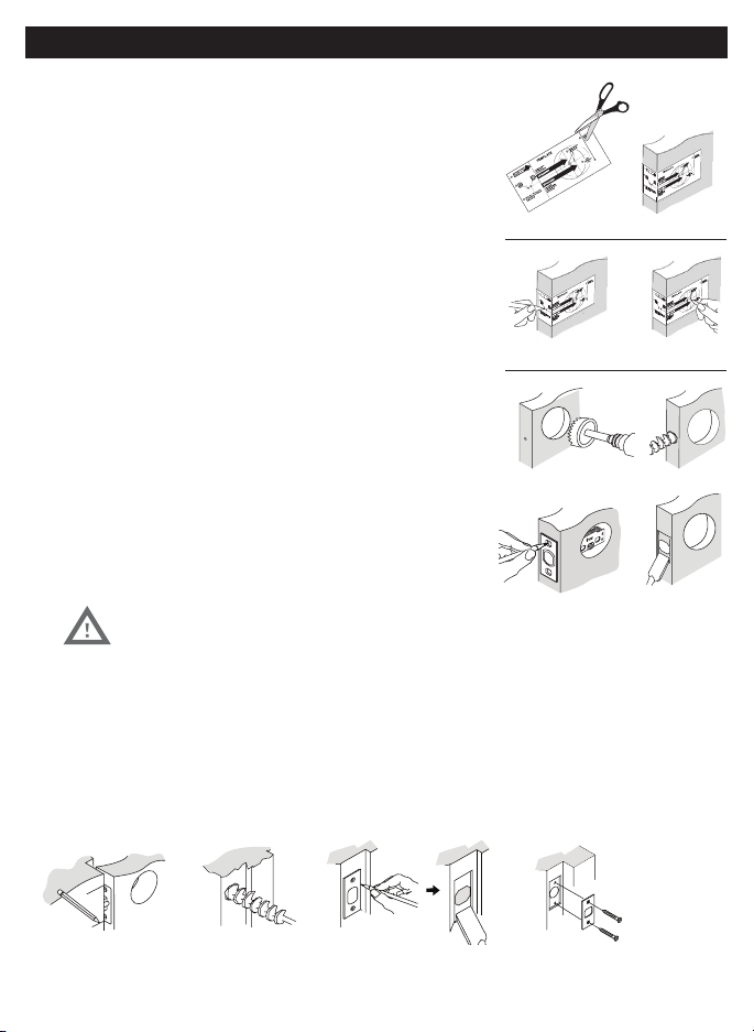
Prepare Door and Jamb............................................................................................................................... Page 2
Adjusting Deadbolt Latch Set.................................................................................................................... Page 3
Installing Deadbolt Latch Set.................................................................................................................... Page 4
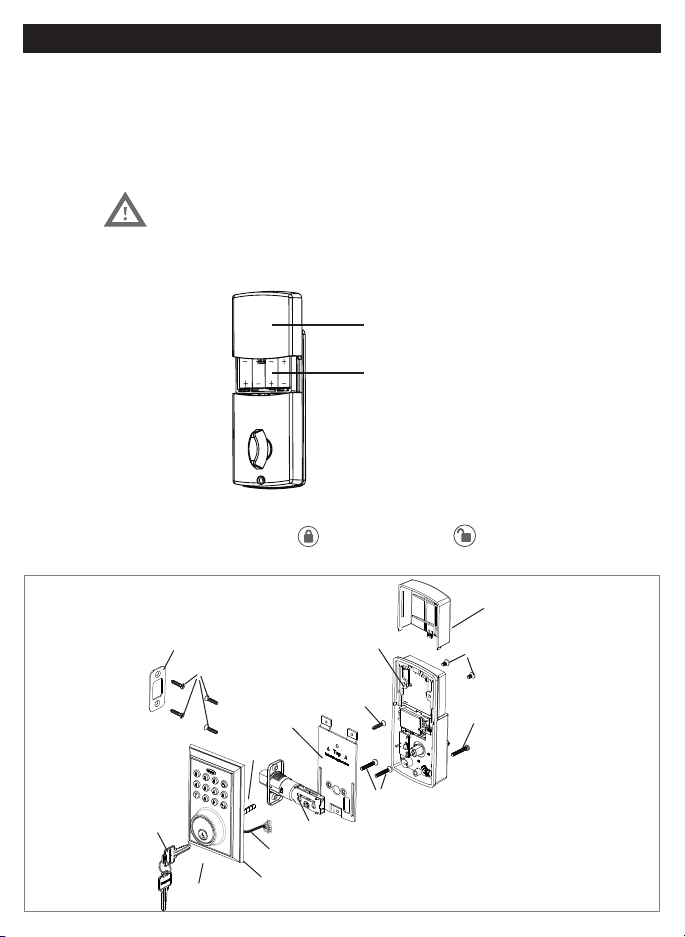
Preparing Interior Assembly....................................................................................................................... Page 5
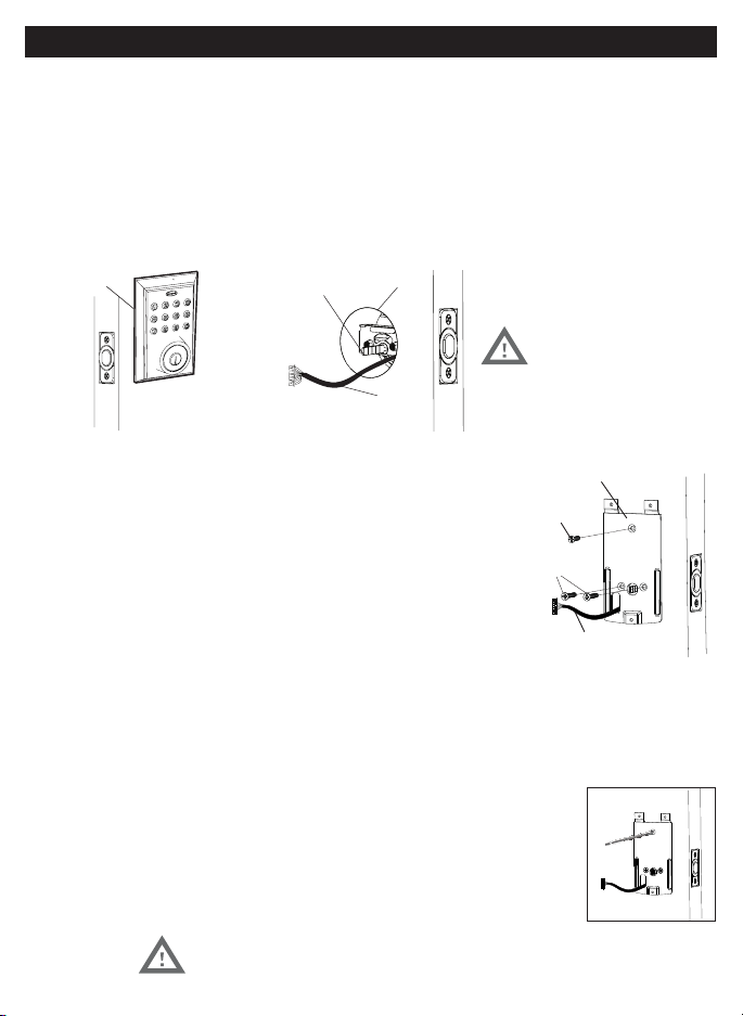
Installing Exterior Assembly...................................................................................................................... Page 6
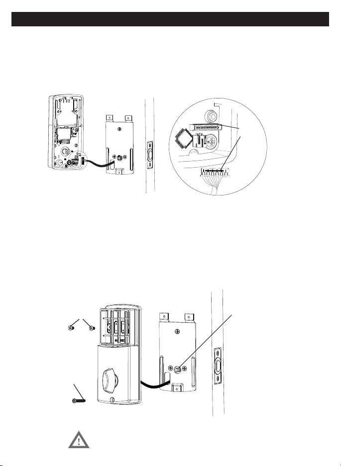
Installing Interior Assembly....................................................................................................................... Page 78
II. MOBILE APPLICATION INSTRUCTIONS
Connect to Lock / Lock Settings ............................................................................................................. Page 10
Lock and Unlock ........................................................................................................................................... Page 11
System Settings............................................................................................................................................. Page 12
Account Management/Notifications ..................................................................................................... Page 13
Send Passcodes and eKeys ........................................................................................................................ Page 14
Manage Users ................................................................................................................................................ Page 1517
III. PHYSICAL KEYPAD PROGRAMMING / TROUBLESHOOTING / ASSISTANCE / WARRANTY
Keypad Programming.................................................................................................................................. Page 18
Turn On/Off Auto Lock Function.............................................................................................................. Page 19
Sound Off......................................................................................................................................................... Page 19
Sound On......................................................................................................................................................... Page 19
Restore Factory Settings............................................................................................................................ Page 19
Add Administrator......................................................................................................................................... Page 20
Customize Passcodes Received from the App...................................................................................... Page 20
EnableDisable AutoLock......................................................................................................................... Page 20
Vacation Mode............................................................................................................................................... Page 20
Disable Vacation Mode................................................................................................................................ Page 20
IV. ASSISTANCE
Trouble Shooting............................................................................................................................................ Page 21
Template........................................................................................................................................................... Page 2223
Consumer Assistance.................................................................................................................................... Page 24
FCC COMPLIANCE......................................................................................................................................... Page 25
Warranty............................................................................................................................................................ Page 26
INDEX

1
PAY CLOSE ATTENTION TO ALERTS
INSTALLATION INSTRUCTIONS
Tools Required for Installation
on Doors That Require Drilling:
Interior Assembly Mounting Plate
Exterior Assembly
Entry keys (2 ea.)
5/16” (8mm) Screws - 2 ea.
3/4” (19mm) Screws - 5 ea. 1” (25mm) Screw - 1 ea.
Deadbolt Strike Plate
Deadbolt Latch Set (Adjustable)
Tools Required for Installation on Pre-drilled Doors:
NOTE: DO NOT USE a drill.
Electronic lock requires (4) High Quality AA Alkaline
batteries. When all 4 batteries are installed in the
correct position, hear 2 beeps and the keypad will
keypad stops illuminating.
Batteries (not included)
PACKAGE CONTENTS
TOOLS REQUIRED

2
NOTE: For installation on doors with pre-drilled holes skip to page 4.
1. TEMPLATE
a. Cut out template printed on page 15 of this Manual
(Figure 1a).
b. Fold template and place on door 36” (915mm) from
the ground as marked (Figure 1b).
2. MARK THE DOOR FOR DRILLING
b. Mark center hole on door edge through guide on
template for 1” (25mm) latch bolt (Figure 2a).
a. Mark center hole on door face through guide on
backset (Figure 2b).
3. DRILL AND CHISEL DOOR
for lock set (Figure 3a).
b. Drill 1” (25mm) hole in center of door edge for
Deadbolt Latch Assembly (Figure 3b).
c. Insert Deadbolt Latch Assembly in hole keeping it
parallel to face of door. Mark outline and remove latch
(Figure 3c).
d. Chisel 1/8” (3mm) deep or until latch face is flush
with door edge (Figure 3d).
4. MARK AND DRILL DOOR JAMB
a. Mark center hole on edge of jamb even with the center of the Latch Bolt on door edge. (Figure 4a).
c. Outline outside edges of Strike Plate (Figure 4c).
d. Chisel 1/8” (3mm) deep for Strike Plate or until flush (Figure 4d).
e. Install Strike Plate using two 3/4” (19mm) screws provided (Figure 4e).
Figure 4a Figure 4b Figure 4c Figure 4e
Figure 4d
NOTE: For Drive in Latch, drill hole size indicated on
template and press until it is flush with door edge.
UP
Figure 1a
Figure 2a Figure 2b
Figure 3a
Figure 3c
Figure 1b
Figure 3b
Figure 3d
PREPARE DOOR AND JAMB

3
NOTE: Deadbolt Latch Set is shipped with the backset set at 23/8” (60mm)
Measure the backset (backset is distance between edge of the door and the
center of Lock).
1. TO CONVERT FROM 23/8” (60mm) BACKSET TO 23/4” (70mm) BACKSET
a. Hold latch with numbers facing forward and thumb pressing on the bolt (Figure 1a).
indicator (Figure 1c).
2. TO CONVERT FROM 23/4” (70mm) BACKSET TO 23/8” (60mm) BACKSET
a. Hold latch with numbers facing forward and thumb pressing on the bolt (Figure 2a).
position indicator (Figure 2c).
NOTE: Do not extend Cylindrical Cover past 23/4” (70mm)
Figure 2a Figure 2b Your latch is now set 2-3/8” (60mm) backset
Cylindrical Cover Extension Plate
2-3/8”
(60mm) 2-3/8”
(60mm)
Figure 2c
Figure 2d
Figure 1a Figure 1b
Figure 1c
Your latch is now set 2-3/4” (70mm) backset
Cylindrical Cover Extension Plate
2-3/8”
(60mm) 2-3/8”
(60mm)
2-3/4”
(70mm)
Figure 1d
ADJUSTING DEADBOLT LATCH SET

4
3. INSTALLING THE DEADBOLT LATCH SET (need phillips head screwdriver)
a. Insert Deadbolt Latch Set into door edge hole with the word
“UP” and the arrow on the extension plate facing UP. Cross
shaped spindle connector will be at the bottom of the Deadbolt
Latch Set (Figure 3a).
b. Make sure the face plate sits flush with the door. Do not force
the latch into the mortise flush. Chisel out excess material if
necessary for a flush fit.
c. Using two 3/4” (19mm). screws provided, screw the latch into the
4. IDENTIFYING YOUR DOOR HANDING
Stand outside the door.
a. If the hinges are on the left your door is Left Handed (Figure 4a).
NOTE: Deadbolt Latch must be retracted when installing
Figure 4a
Left Handed Door
Hinges are on the left side
Hinges are on the right side
Figure 4b
Figure 3a
NOTE: You are standing outside the door
Deadbolt Latch Extended
Deadbolt Latch Retracted
INSTALLING DEADBOLT LATCH SET

5
6. SET THE ENTRY SWITCH FOR LEFT OR RIGHT HANDED DOOR
a. Gently move the switch to “L” for Left Handed Door (Figure 6a).
7. SET THE INTERIOR KNOB POSITION FOR LEFT OR RIGHT HAND HINGED DOORS
Entry Switch
(Left or Right)
Figure 6a-b
Right Handed Door
(Vertical)
Left Handed Door
(Horizontal)
NOTE: Deadbolt Latch must be retracted when installing
5. UNPACK THE INTERIOR ASSEMBLY
Mounting Plate from the Interior Assembly.
NOTE: Make sure deadbolt Latch is retracted
Figure 6a-b
PREPARING THE INTERIOR ASSEMBLY

6
Right handed door view
Figure 9a-f
Gasket
Control
Wire
Latch Hole
Figure 8a Figure 8c
C
3/4”(19mm) screw
(Optional Instalation)
Mounting Plate
Control Wire
B
9. SECURING THE EXTERIOR ASSEMBLY TO THE DOOR
door”, route the Control Wire through the
rectangular slot in the Mounting Plate
(Figure 9a).
b. Place Mounting Plate against door with tailpiece passing
through the center hole in the three hole set (Figure 9b).
c. Secure the Mounting Plate to the Exterior Assembly using
(Figure 9c).
d. Hand tighten with a Phillips Screwdriver leaving loosely connected (Figure 9d).
f. Check vertical alignment of the lock (Figure 9f).
DO NOT OVER TIGHTEN
10. OPTIONAL INSTALLATION
a. Using a 1/16” (2mm) drill bit, drill a pilot hole in your door using the
b. Insert one 3/4” (19mm) screw and tighten.
8. INSTALLING THE EXTERIOR ASSEMBLY
Work with the Door Open for easy access.
a. Unpack the Exterior Assembly. Use care to not scratch the green circuit board during handling and installation.
c. Insert the Exterior Assembly onto the door with the tailpiece going through the Deadbolt Latch Set cross
shaped spindle connector in the VERTICAL POSITION
Deadbolt Latch Set (Figure 8c).
NOTE: Tailpiece must be
positioned vertically
NOTE: Lock and unlock using the key to see if
the Deadbolt Latch is opening and closing easily.
INSTALLING EXTERIOR ASSEMBLY

Figure 12a
A
5/16” (8mm) screws
1”(25mm) screw
D
Figure 11a
Match Color
NOTE: Tailpiece must be
positioned vertically
11. ATTACH THE CONTROL WIRE TO THE INTERIOR ASSEMBLY
a. Use care to attach the Control Wire male plug to the Interior Assembly female
socket connector.
b. Carefully insert the male plug, smooth side up, into the female socket on the
12. ATTACH THE INTERIOR ASSEMBLY TO DOOR
a. IMPORTANT:
left hand door.
b. Make sure the tailpiece (Figure 12a) is in the vertical position.
c. Position the Interior Assembly over the vertically positioned tailpiece and carefully push
the Interior Assembly against the door (Figure 12a).
d. Using two 5/16” (8mm) screws and one 1” (25mm) screw, attach the Interior Assembly to the Mounting
Plate. DO NOT OVER TIGHTEN SCREWS
NOTE: Lock and unlock using Interior Knob to see if
the latch is opening and closing easily.
INSTALLING INTERIOR ASSEMBLY

8
13. INSTALLING BATTERIES
a. Slide battery cover up and remove.
b. Insert 4 AA high quality Alkaline batteries into the Battery Compartment in the
the Honeywell button will flash green twice to signify that it has received power (Figure 13a).
batteries (Figure 13b).
14. TESTING LOCK
a. Always test with the Door Open
to unlock.
Battery
Cover
4 AA
Batteries
NOTE: Do not touch the Keypad until the blue light turns off.
Do not use rechargeable batteries or non-alkaline batteries.
Figure 13a-b
INSTALLATION OVERVIEW
Strike Plate
3/4”(19mm) screws(C)
Mounting Plate
Optional
3/4”(19mm) screw(C)
Interior Assembly
Battery Cover
5/16”(8mm) screw(A)
1”(25mm) screw(D)
Latch
Control Wire
Exterior Assembly
Key
INSTALLING INTERIOR ASSEMBLY

9
PRIMARY APP ICONS
Messages User
Unlock Users
Save Menu Dropdown
Edit
Settings eKey Passcode
KEYPAD SYMBOLS
USER TYPES
Administrative User - Able to send & delete eKeys & Passcodes,
change AP , and remove connected lock(s)
Authorized User - Able to send eKeys & Passcodes, can delete
only the eKeys & Passcodes they send
User - Able to use eKeys & Passcodes assigned from
A
AP
AU
U
After you have installed your Bluetooth Lock, download the free “Honeywell Lock” App on your smart phone
using one of the following options:
1. Search “Honeywell Lock” in the App Store or Google Play Store.
1. Open the App after it has been installed on your Smartphone.
3. Follow prompts on screen and enter Mobile Phone Number and Password
4. Select “Get Code”
IMPORTANT:
5. Input received verification code
6. Select “Create Account”
Administrator
Passcode
New
Passcode
NP
Passcode
RP
VERY IMPORTANT
Before connecting to a lock please
ensure that Bluetooth is enabled on
your phone and you are standing in
front of the lock, and it is activated.
Once the door is unlocked with the
App, you will have to manually lock
it. (See page 11 to set the Auto Lock
feature)
Ensure that Push Notifications are
enabled for the App.
After connecting to a new lock as
an A, the factory default Passcode
will be deleted, and replaced with a
new AP , which is randomly assigned,
and should be changed in the lock’s
settings immediately.
Add Device
Locks Safes
See page 16 for information on
features and settings for the App.
NP RP
HONEYWELL LOCK MOBILE APPLICATION INSTALLATION & USE
APPLICATION SETUP OPTIONS
REGISTER APP AND CREATE ACCOUNT

IMPORTANT: Your Bluetooth must be enabled and you must be within range of the lock.
1. Press any key on Lock to activate the Lock. (Digital keys are lit when activated).
3. Select which type of lock you would like to add
4. Click on available lock
5. Follow prompts to name the device
After you have connected the lock to the Bluetooth App, the Admin. Digital Passcode must be reprogrammed by
going to the “Lock Setting” page.
Go to “Lock Settings” by selecting the “Settings icon “*” in the top right corner of the screen.
SET ADMIN PASSCODE
IMPORTANT: Your Bluetooth must be enabled and you must be within range of the lock.
1. Select “Admin Passcode” from the list.
2. You will be prompted to enter your Account Password.
3. Enter a new 4 to 9 digit password of your choice and press “DONE”.
CHANGE LOCK NAME
1. Select “Name” from the list
2. Input the name you want to assign to this lock and press “DONE”.
ACTIVATE AUTO LOCK
1. Select “Auto Lock” from the list
2.
3.
4. Press “OK” to Save changes
NOTE: Auto lock can also be programmed using the digital keypad
ADD LOCK TO GROUP
If no groups exist you will have to create one. Press “Create Group” and enter the group name.
1. Select “Group” from the list.
2.
3. Select the Group to place the lock in.
4.
UPGRADE THE CONNECTED LOCK
In order to upgrade you have to be the AP for the lock, and within Bluetooth range
that the lock is upgrading.
1. Press “Lock Upgrade” from the list to Check for Updates
2. Press “Upgrade’ (in case a pop up notification appears, follow it to finish the upgrade).
CONNECT TO BLUETOOTH LOCK
MANAGE LOCK SETTINGS

11
UNLOCK DOOR WITH THE APP
2.
LOCK DOOR WITH THE APP
1. Open the App
2. Click on the connected safe you wish to lock
3. Press and hold the lock button until the safe has locked.
AUTO LOCK
UNLOCK DOOR WITH KEYPAD
1. Press any key on Lock to activate the Lock. (Digital keys are lit when activated).
2.
LOCK DOOR WITH THE KEYPAD
1. Press the button on the keypad.
TOUCH TO UNLOCK
IMPORTANT: Your Bluetooth must be enabled and you must be within range of the lock.
1.
2. Press any key on Lock to activate the Lock. (Digital keys are lit when activated).
3. Press any key to unlock.
USING APP TO LOCK AND UNLOCK
USING KEYPAD TO LOCK AND UNLOCK

12
1. Go to the Main menu by pressing the * icon at the top left corner of the screen.
2. Select “System Settings”
3. Select below settings as desired.
PATTERN PASSWORD
Create a pattern to unlock the App. Provides extra security
BEEP ON UNLOCKING
Mute or enable a sound when the door is unlocked
VIBRATION
Enable or disable the App’s vibration feature
TOUCH TO UNLOCK
MANAGE GROUPS
Assign locks to groups
WIFI GATEWAY
Connect and use the App in conjunction with an Internet Gateway
SECURITY SETTING –
Adjust the following settings
RESET LOCK VERIFICATION –
Notifications when the lock is reset
SEND EKEY VERIFICATION –
Notification when an eKey is sent
SEND PASSCODE VERIFICATION –
Notification when a Passcode is sent
DELETE EKEY VERIFICATION –
Notification when an eKey is deleted
CHANGE MANAGEMENT PASSCODE VERIFICATION –
Notification when a Passcode is changed
AUTHORIZE VERIFICATION –
SYSTEM SETTINGS

13
1. Go to the Main menu by pressing the * icon at the top left corner of the screen.
2. Select “Account Management”
3. Select below settings as desired.
PROFILE PICTURE
1. Click on the picture at the top of the page
2. Change the picture associated with the account by clicking the icon
NICKNAME
1. Click on “Nickname”.
2. Enter a nickname for the account.
EMAIL/MOBILE NUMBER
1. Click on “Email”
2. Enter an email address to the account.
3. Select “Get Code”
IMPORTANT:
4. Select “Admin Passcode” from the list.
RESET PASSWORD –
1.
2.
1. Open the App
2. Select the icon at the top right of the Home screen
3. Select the message you would like to read
ACCOUNT MANAGEMENT
VIEW NOTIFICATIONS

14
CREATE & SEND PASSCODES BY EMAIL OR TEXT MESSAGE
CREATE AND SEND EKEYS
Passcodes can be sent via email or text to any SMS enabled mobile device.
SENDING PASSCODES
1. Select the lock you want to send a Passcode for
2. Select the in the bottom menu
Permanent Passcodes –
a. Select “Permanent” from the top tabs
Timed Passcodes –
b. Input the time frame
Cyclic (Recurring) Passcodes
a. Select “Cyclic” from the top tabs
b. Input the time frame
OneTime Passcodes
3. Press “Generate” to get a new Passcode
4. Input the mobile number, or email address you would like to send the Passcode to
5. Press “Send by email” or “Send by Msg.”
-
tered, or the wrong information is input when sending an eKey.
SENDING EKEYS
1. Select the lock you want to send a Passcode for.
2. Select the in the bottom menu.
NOTE:
Permanent Passcodes –
a. Select “Permanent” from the top tabs
b. Enter the receiver’s Account Name
Timed Passcodes –
b. Input the time frame
c. Enter the receiver’s Account Name
d. Press send
3. You will receive a notification once the key has been received

15
MANAGE USERS
Ensure that WiFi is connected and working in order to manage Users associated with a connected lock
FREEZE A USERS’ EKEY
1.
2. Select the in the bottom menu
3.
4.
5.
CHANGE AU TO A
1.
2.
3. Select the in the bottom menu
4. Select the top eKey tab
5.
6.
Input your account Password
8. Once that User’s account has changed you will be notified
RENAME USERS
1. Select the lock with the eKey you want to rename
2. Select the in the bottom menu
3. Select the top eKey tab
4.
5.
6. Input the new name you would like to use
EDIT TIME FRAME
1. Select the lock with the eKey you want to edit
2. Select the in the bottom menu
3. Select the top eKey tab
4.
5. Select on the screen
6. Change the time frame for the User

16
CLEAR USER EKEYS
1. Select the lock with the eKeys you want to clear
2. Select the in the bottom menu
3. Select the top right icon
4. Select “Clear”
5. Input your account password
6. Confirm the action
RESET USER EKEYS
When you reset eKeys, all eKeys will be removed from the lock.
1. Select the lock with the eKeys you want to reset
2. Select the in the bottom menu
3. Select the top right icon
4.
5. Input your account password
6. Confirm the action
DELETE A USERS’ EKEY
1. Select the lock with the eKeys you want to clear
2. Select the in the bottom menu
3. Select the User you would like to Delete
4. Select “Clear”
5. Select “Delete” from the top tab
6. Confirm that you would like to Delete the User
RENAME PASSCODES
1. Select the lock with the Passcode you want to rename/name
2. Select the in the bottom menu
3. Select “Passcode” from the top tab
4.
5.
6. Input the new name you would like to use
DELETE PASSCODES
1. Select the lock with the Passcode you want to delete
2. Select the in the bottom menu
3. Select “Passcode” from the top tab
4. Select the Passcode to Delete
5. Select ”Delete”
6. Confirm the action
MANAGE USERS

MANAGE USERS
RESET PASSCODES
When you reset eKeys, all eKeys will be removed from the lock.
1. Select the lock the Passcode is associated with
2. Select the in the bottom menu
3. Select “Passcode” from the top tab
4. Select the Dropdown icon
5.
6. Input your account password

18
EXTERIOR ASSEMBLY OVERVIEW
Indicator light
Green
Red
l
The electronic lock requires four (4) High Quality AA
Alkaline batteries. When all 4 batteries are installed
in the correct position, you will hear 2 beeps and
the keypad will illuminate blue. DO NOT TOUCH the
keypad until the keypad stops illuminating.
Batteries (not included)
Unlock button
Lock - Use to lock door
Lock button
App in order to program the keypad.
By default the factory keypad passcode is 1234
Change the Administrator passcode AP so
it can easily be remembered by you after
connecting to a lock.
Once you connect the App to the lock, the
factory keypad passcode will be changed to
a new code, which can be found in the lock’s
settings.
Unlock - Used to unlock door
Programming - Used in programming steps
VERY IMPORTANT
Received Code (69 digits)
Complete all the programming steps in the programming mode
within 5 seconds.
Use the key to clear entries in case a wrong button is pushed.
Programming Symbols
New Code (49 digits)
Lock / Clear
Administrator Passcode
Administrator Passcode:
AP
AP
RP
NP
(Admin Passcode is located on the Honeywell App under
Lock Settings.)
Unlock / Programming
KEY PAD PROGRAMMING OPTIONAL
This manual suits for next models
1
Table of contents
Other Honeywell Door Lock manuals