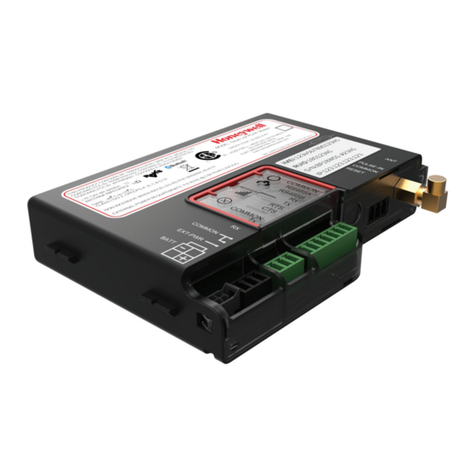
Honeywell XYR 400E User manual

XYR 400E Wireless Ethernet
User's Manual
34-XY-25-26
Version 1
5/1/08

Version 1 XYR400E Ethernet Modem 2
5/1/08
Notices and Trademarks
Copyri ht 2008 by Honeywell International Inc.
Version 1 May 1, 2008
While this information is presented in good faith and believed to be accurate, Honeywell disclaims the implied warranties of
merchantability and fitness for a particular purpose and makes no express warranties except as may be stated in its written agreement
with and for its customers.
In no event is Honeywell liable to anyone for any indirect, special or consequential damages. The information and specifications in
this document are sub ect to change without notice.
Honeywell, PlantScape, Experion PKS, and TotalPlant are registered trademarks of Honeywell International Inc.
Other brand or product names are trademarks of their respective owners.
Honeywell International
Process Solutions
2500 West Union Hills
Phoenix, AZ 85027
1-800 343-0228

3 XYR400E Ethernet Modem Version 1
5/1/08
About This Document
This document describes preparation, operation and maintenance of the XYR 400E Ethernet Modem. Mounting,
installation and wiring are covered in other documents.
Honeywell does not recommend using devices for critical control where there is a single point of failure or where single
points of failure result in unsafe conditions. XYR3000 is targeted at open loop control, supervisory control, and controls
that do not have environmental or safety consequences. As with any process control solution, the end-user must weigh the
risks and benefits to determine if the products used are the right match for the application based on security, safety, and
performance. Additionally, it is up to the end-user to ensure that the control strategy sheds to a safe operating condition if
any crucial segment of the control solution fails.
Revision Information
Document Name Document
ID
Version
Number
Publication Date
XYR 400E Wireless Ethernet User’s M nu l 34-XY-25-26 5/1/2008
References
The following list identifies all documents that may be sources of reference for material discussed in this publication.
Document Title
Getting St rted with Honeywell One Wireless solutions
XYR3000 MSG
How to build n XYR3000 system

Version 1 XYR400E Ethernet Modem 4
5/1/08
Support and Contact Information
United States and Canada
Contact: Honeywell Solution Support Center
Phone: 1-800 822-7673. In Arizona: 602- 313-5558
Calls are answered by dispatcher between 6:00 am and 4:00 pm Mountain Standard
Time. Emergency calls outside normal working hours are received by an answering
service and returned within one hour.
Facsimile: (602) 313-3293
Mail: Honeywell TAC, MS P13
2500 West Union Hills Drive
Phoenix, AZ, 85027
World Wide Web
Honeywell Solution Support Online:
http://www.honeywell.com/ps
lsewhere
Call your nearest Honeywell office.
Training Classes
Honeywell Automation College:
http://www.automationcollege.com

5 XYR400E Ethernet Modem Version 1
5/1/08
Symbol Definitions
The following table lists those symbols used in this document to denote certain conditions.
Symbol Definition
ATT NTION: Identifies inform tion th t requires speci l consider tion.
TIP: Identifies dvice or hints for the user, often in terms of performing t sk.
CAUTION
Indic tes situ tion which, if not voided, m y result in equipment or work (d t ) on
the system being d m ged or lost, or m y result in the in bility to properly oper te
the process.
CAUTION: Indic tes potenti lly h z rdous situ tion which, if not voided, m y
result in minor or moder te injury. It m y lso be used to lert g inst uns fe
pr ctices.
CAUTION symbol on the equipment refers the user to the product m nu l for
ddition l inform tion. The symbol ppe rs next to required inform tion in the
m nu l.
WARNING: Indic tes potenti lly h z rdous situ tion, which, if not voided, could
result in serious injury or de th.
WARNING symbol on the equipment refers the user to the product m nu l for
ddition l inform tion. The symbol ppe rs next to required inform tion in the
m nu l.
WARNING, Risk of electrical shock: Potenti l shock h z rd where HAZARDOUS
LIVE volt ges gre ter th n 30 Vrms, 42.4 Vpe k, or 60 VDC m y be ccessible.
SD HAZARD: D nger of n electro-st tic disch rge to which equipment m y be
sensitive. Observe prec utions for h ndling electrost tic sensitive devices.
Protective arth (P ) terminal: Provided for connection of the protective e rth
(green or green/yellow) supply system conductor.
Functional earth terminal: Used for non-s fety purposes such s noise immunity
improvement. NOTE: This connection sh ll be bonded to Protective E rth t the
source of supply in ccord nce with n tion l loc l electric l code requirements.
arth Ground: Functional earth connection. NOTE: This connection sh ll be
bonded to Protective E rth t the source of supply in ccord nce with n tion l nd
loc l electric l code requirements.
Chassis Ground: Identifies connection to the ch ssis or fr me of the equipment
sh ll be bonded to Protective E rth t the source of supply in ccord nce with
n tion l nd loc l electric l code requirements.

Version 1 XYR400E Ethernet Modem 6
5/1/08
CONTENTS
CHAPTER ONE INTRODUCTION ............................................................................ 8
1.1 N
ETWORK
T
OPOLOGY
..................................................................................................... 8
1.2 G
ETTING
S
TARTED
Q
UICKLY
........................................................................................ 11
CHAPTER TWO INSTALLATION ............................................................................. 11
2.1 G
ENERAL
...................................................................................................................... 11
2.2 A
NTENNA
I
NSTALLATION
.............................................................................................. 12
2.2.1 Dipole and Collinear antennas................................................................................. 14
2.2.2 Directional antennas. ............................................................................................... 15
2.3 P
OWER
S
UPPLY
............................................................................................................. 16
2.4 S
ERIAL
C
ONNECTIONS
.................................................................................................. 16
2.4.1 RS232 Serial Port ................................................................................................ 16
2.4.2 RS485 Serial Port ................................................................................................ 17
2.5 D
ISCRETE
(D
IGITAL
)
I
NPUT
/O
UTPUT
............................................................................. 19
CHAPTER THREE OPERATION............................................................................. 19
3.1 S
TART
-
UP
...................................................................................................................... 19
3.2 S
ELECTING A
C
HANNEL
................................................................................................ 21
3.3 D
EFAULT
C
ONFIGURATION
........................................................................................... 23
3.4 C
ONFIGURING THE
U
NIT FOR THE
F
IRST
T
IME
............................................................... 23
3.4.1 Set PC to same network as XYR 400E................................................................... 23
3.4.2 Set XYR 400E to same network as PC.................................................................... 26
3.5 N
ETWORK
C
ONFIGURATION
.......................................................................................... 28
3.6 E
THERNET
D
ATA
........................................................................................................... 30
3.7 N
ORMAL
O
PERATION
.................................................................................................... 31
3.8 R
ADIO
C
ONFIGURATION
................................................................................................ 32
3.9 S
PANNING
T
REE
A
LGORITHM
/
R
EDUNDANCY
.............................................................. 34
3.10 M
ULTIPLE
AP
R
EPEATER
M
ESH
N
ETWORK
................................................................... 35
3.11 R
OUTING
R
ULES
........................................................................................................... 42
3.12 W
IRELESS
M
ESSAGE
F
ILTERING
.................................................................................... 45
3.13 S
ERIAL
P
ORT
C
ONFIGURATION
...................................................................................... 47
3.13.1 RS-232 PPP Server .............................................................................................. 47
3.13.2 Serial Gateway..................................................................................................... 52
3.13.3 Modbus TCP to RTU Gateway............................................................................ 54
3.14 D
IGITAL
I
NPUT
/O
UTPUT
................................................................................................ 55
3.15 M
ODBUS
I/O
T
RANSFER
................................................................................................ 55
3.16 M
ODULE
I
NFORMATION
C
ONFIGURATION
..................................................................... 60
3.17 R
EMOTE
C
ONFIGURATION
............................................................................................. 60
3.18 C
ONFIGURATION
E
XAMPLES
......................................................................................... 61

7 XYR400E Ethernet Modem Version 1
5/1/08
CHAPTER FOUR DIAGNOSTICS.................................................................................. 65
4.1 D
IAGNOSTICS
C
HART
.................................................................................................... 65
4.2 D
IAGNOSTIC
I
NFORMATION
A
VAILABLE
....................................................................... 66
4.2.1 Connectivity......................................................................................................... 66
4.2.2 Monitor Communications.................................................................................... 67
4.2.3 Statistics............................................................................................................... 68
4.2.4 Network Traffic Analysis..................................................................................... 68
4.3 T
ESTING
R
ADIO
P
ATHS
................................................................................................. 68
4.4 U
TILITIES
...................................................................................................................... 69
4.4.1 PING ........................................................................................................................ 69
4.4.2 IPCONFIG ............................................................................................................... 71
4.4.4 ROUTE .................................................................................................................... 72
CHAPTER FIVE SPECIFICATIONS .......................................................................... 74
APPENDIX A FIRMWARE UPGRADE ......................................................................... 76
APPENDIX B GLOSSARY ............................................................................................... 82

Version 1 XYR400E Ethernet Modem 8
5/1/08
Chapter One INTRODUCTION
The XYR 400E Industrial WiFi Wireless Ethernet module provides wireless connections between
Ethernet devices or Ethernet wired networks (LAN’s). It complies with the IEEE 802.11b standard.
The XYR 400E has an internal 2.4GHz direct sequence spread spectrum (DSSS) wireless transceiver,
which can be used without a radio license in most countries. Users can select one of 11 x 5 MHz
wide channels, with the first channel centred at 2.412 GHz.
Note that regulations in North America and part of Europe permit all 11 channels to be
used in these countries. Please check with your HONEY ELL representative for the
permitted channel usage in your country.
The XYR 400E unit also provides two serial connections as well as the Ethernet connections. It is
possible to use all three data connections concurrently, allowing the XYR 400E to act as a Device
Server. Wireless connections can be made between serial devices and Ethernet devices, however
appropriate driver applications are required in the host devices to handle the different data format.
The XYR 400E does provide connection functionality between serial “Modbus RTU” devices and
Ethernet “Modbus TCP” devices.
The XYR 400E is available in two models with different RF power:
XYR 400E-100 100mW of RF power
XYR 400E-300 300mW of RF power
Note that European regulations do not permit more than 100m of RF power to be used.
In USA, Canada and Australia, up to 1 of RF power may be generated. In other
countries, please check with your HONEY ELL representative.
The XYR 400E has a standard RJ45 Ethernet connection which will operate at up to 100Mbit/sec.
The module will transmit the Ethernet messages on the wireless band at rates between 1 and 11
Mbit/sec.
1.1 Network Topolo y
The XYR 400E is an Ethernet device, and must be configured as part of an Ethernet network. Each
XYR 400E must be configured as:
an “Access Point” or a “Client”, and
a “Bridge” or a “Router”.
You can also connect to the XYR 400E via a RS232 or
RS485 serial port using serial server or PPP (point-to-point) protocol. PPP allows the XYR 400E to
connect serial communications into the Ethernet network.
Client
Ethernet
Device
Access
Point

9 XYR400E Ethernet Modem Version 1
5/1/08
LAN
Ethernet device
Client
Access
Point
Client
Access Point vs Client
The Access Point unit acts as the “wireless
master” unit. The Access Point sets up the
wireless links to the Client units, and controls
the wireless communications. The first diagram
shows two Ethernet devices being linked. One
XYR 400E is configured as an Access Point and
one as a Client - in this example it doesn’t mater
which unit is the Access Point.
The second diagram shows an existing LAN being
extended using XYR 400E’s. In this example, the
Access Point should be configured at the LAN end
- although the wireless link will still work if the
Client is at the LAN end.
An Access Point can connect to multiple Clients. In
this case, the Access Point should be the “central”
unit.
An Access Point could be used as a “Repeater” unit
to connect two XYR 400E Clients which do not have direct reliable radio paths.
Multiple Access Points can be set-up in a “mesh” network to provide multiple repeaters.
LAN
Ethernet Device
Client
Access
Point
LAN
Ethernet Device
Client
Access
Point
Client
Client
LAN
Client
Access
Point
Client
Access
Point Access
Point
Client

Version 1 XYR400E Ethernet Modem 10
5/1/08
Brid e vs Router
Each XYR 400E is configured with an IP address for the Ethernet side, and another for the wireless
side.
A Brid e connects devices within the same Ethernet network - for example, extending an existing
Ethernet LAN. For a
Bridge, the IP address for
the wireless side is the
same as the Ethernet side.
A Router connects devices on different LAN’s. The IP addresses for the Ethernet and wireless sides
are different.
In the above example, the wireless link is part of LAN A, with the Client unit acting as a Router
between LAN A and LAN B. Alternately, the Access Point could be configured as a Router - the
wireless link is then part of LAN B.
LAN A
Client
Bridge
Access Point
Router
•192.168.0.34
•169.254.102.54
LAN B
•169.254.102.17
•169.254.102.53
If more than two routers are required within the same radio network, then routing rules may need to
be configured (refer section “3.11 Routing Rules” for further details). There is no limit to the number
of Bridges in the same network - although there is a limit of 128 Client units linked to any one
Access Point.
LAN
Client
Bridge
Access Point
Bridge
•192.168.0.34
•192.168.0.34 •192.168.0.72
192.168.0.72
LAN A
Client
Router
Access Point
Bridge
•192.168.0.34
•192.168.0.34
LAN B
•169.254.102.17
•192.168.0.72

11 XYR400E Ethernet Modem Version 1
5/1/08
1.2 Gettin Started Quickly
Most applications for the XYR 400E require little configuration. The XYR 400E has many
sophisticated features, however if you don’t require these features, this section will allow you to
configure the units quickly.
First, read Section 2, “Installation”. The XYR 400E requires an antenna and a power supply.
Power the XYR 400E and make an Ethernet connection to your PC (for further information on
how to do this, refer to section 3.4)
Set the XYR 400E address settings as per section 3.4
Save the configuration - the XYR 400E is now ready to use.
Before installing the XYR 400E, bench test the system. It is a lot easier to locate problems when the
equipment is all together.
There are other configuration settings which may or may not improve the operation of the system.
For details on these settings, refer to section 3.
Chapter Two INSTALLATION
2.1 General
The XYR 400E module is housed in an rugged aluminium case, suitable for DIN-rail mounting.
Terminals will accept wires up to 2.5 sqmm (12 gauge) in size.
All connections to the module must be SELV. Normal 110-250V mains supply should not
be connected to any terminal of the XYR 400E module. Refer to Section 2.3 Power Supply.
Before installing a new system, it is preferable to bench test the complete system. Configuration
problems are easier to recognize when the system units are ad acent. Following installation, the
most common problem is poor communications caused by incorrectly installed antennas, or radio
Client
Router
LAN C
169.254.102.17
192.168.0.73
LAN A
Client
Bridge
Access Point
Bridge
192.168.0.34
192.168.0.34
192.168.0.72
192.168.0.72
Client
Router
LAN B
169.254.109.40
192.168.0.74

Version 1 XYR400E Ethernet Modem 12
5/1/08
interference on the same channel, or the radio path being inadequate. If the radio path is a
problem (i.e. path too long, or obstructions in the way), then higher performance antennas or a
higher mounting point for the antenna may rectify the problem. Alternately, use an intermediate
XYR 400E Module as a repeater.
The foldout sheet XYR 400E Installation Guide provides an installation drawing appropriate to
most applications. Further information is detailed below.
Each XYR 400E module should be effectively earthed via the "GND" terminal on the XYR 400E
module - this is to ensure that the surge protection circuits inside the XYR 400E module are
effective.
2.2 Antenna Installation
The XYR 400E module will operate reliably over large distances. The distance which may be
reliably achieved will vary with each application - depending on the type and location of
antennas, the degree of radio interference, and obstructions (such as buildings or trees) to the
radio path.
The maximum range achievable depends on the regulated RF power permitted in your country,
and whether you use separate transmit and receive antennas. With a single antenna, 5 km (3
miles) can be achieved in USA, Canada and Australia (4W ERP) and 1km in Europe (100mW
ERP). With separate transmit and receive antennas, more than 10km (6 miles) can be achieved
in USA, Canada and Australia and more than 5 km in Europe.
To achieve the maximum transmission distance, the antennas should be raised above
intermediate obstructions so the radio path is true “line of sight”. The modules will operate
reliably with some obstruction of the radio path, although the reliable distance will be reduced.
Obstructions which are close to either antenna will have more of a blocking affect than
obstructions in the middle of the radio path. The XYR 400E modules provide a diagnostic feature
which displays the radio signal strength of transmissions (refer Diagnostics section).
Line-of-sight paths are only necessary to obtain the maximum range. Obstructions will reduce
the range, however may not prevent a reliable path. A larger amount of obstruction can be
tolerated for shorter distances. For short distances, it is possible to mount the antennas inside
buildings. An obstructed path requires testing to determine if the path will be reliable - refer the
section 6 of this manual.
Where it is not possible to achieve reliable communications between two XYR 400E modules,
then a third XYR 400E module may be used to receive the message and re-transmit it. This
module is referred to as a repeater. This module may also have a host device connected to it.
The XYR 400E unit has two antenna connections at the top of the module, allowing two
antennas to be fitted to the unit. The left connector (looking at the front) labeled “RX” is
connected only to the internal wireless receiver. The right connector labeled TX/RX is connected
to both the transmitter and receiver.
Note: when only one antenna is used, it must be connected to the right TX/RX connector.

13 XYR400E Ethernet Modem Version 1
5/1/08
Plant and factory installations
Most installations in industrial plants and factories use a single omni-directional antennas.
Installations can suffer from “multi-path fading” effects where multiple reflected radio signals
adversely affect the signal strength. This can be checked by moving the antenna a short distance
(10 cm or 4 inches) - if the signal increases significantly then there are multi-path effects.
In a “static” installation, where the radio path is not changing, moving an antenna to the
position of maximum signal solves this problem. However where the radio path changes because
the XYR 400E is mounted on moving equipment, or if there is moving equipment in the area,
then the solution is to use two antennas. Because the two connectors are separated, the RF
signal at each connector will be different in the presence of multi-path fading. The XYR 400E
unit will automatically select the higher RF signal.
Note that directional antennas are not normally used in plant and factory installations.
Line-of-si ht installations
In longer line-of-sight installations, the range may be increased by using a high gain antenna on
the TX/RX connector. However the gain should not cause the effective radiated power (ERP) to
exceed the permitted value. A second higher gain antenna can be connected to the RX connector
without affecting ERP - this will increase the operating range provided the background noise in
the area is low.
Antennas
Antennas can be either connected directly to the module connectors or connected via 50 ohm
coaxial cable (eg RG58 Cellfoil or RG213) terminated with a male SMA coaxial connector. The
higher the antenna is mounted, the greater the transmission range will be, however as the length
of coaxial cable increases so do cable losses.
The net gain of an antenna/cable configuration is the gain of the antenna (in dBi) less the loss in
the coaxial cable (in dB). The maximum net gain of the antenna/cable configuration connected
to the TX/RX connector is 0dB in Europe (100mW ERP). In USA, Canada and Australia (4W
ERP), the maximum gain is 12dB for the XYR 400E-300 or 16dB for the XYR 400E-100.
There is no gain restriction for antennas connected to the RX connector.

Version 1 XYR400E Ethernet Modem 14
5/1/08
The gains and losses of typical antennas are
Antenna Gain (dBi)
Dipole 2
Collinear 5 or 8
Directional 10 - 28
Cable type Loss (dB per 10 m / 30 ft)
RG58 Cellfoil -6
RG213 -5
LDF4-50 -1.5
The net gain of the antenna/cable configuration is determined by adding the antenna gain and the
cable loss. For example, a 5dBi antenna with 10 metres of Cellfoil has a net gain of -1 dB (5dB
– 6dB).
Installation tips
Connections between the antenna and coaxial cable should be carefully taped to prevent ingress
of moisture. Moisture ingress in the coaxial cable is a common cause for problems with radio
systems, as it greatly increases the radio losses. We recommend that the connection be taped,
firstly with a layer of PVC Tape, then with a vulcanizing tape such as “3M 23 tape”, and finally
with another layer of PVC UV Stabilized insulating tape. The first layer of tape allows the oint
to be easily inspected when trouble shooting as the vulcanizing seal can be easily removed.
Where antennas are mounted on elevated masts, the masts should be effectively earthed to avoid
lightning surges. For high lightning risk areas, surge suppression devices between the module
and the antenna are recommended. If the antenna is not already shielded from lightning strike by
an ad acent earthed structure, a lightning rod may be installed above the antenna to provide
shielding.
2.2.1 Dipole and Collinear antennas
A dipole or collinear antenna transmits the same amount of radio power in all directions - as
such that are easy to install and use. The dipole antenna with integral 5 metres (15 feet) cable
does not require any additional coaxial cable, however a cable must be used with the collinear
antennas.
Collinear and dipole antennas should be mounted vertically, preferably 30 cm (1 foot) away from
a wall or mast to obtain maximum range.

15 XYR400E Ethernet Modem Version 1
5/1/08
45
o
DIRECTIONAL
ANTENNA
2.2.2 Directional antennas.
Directional antennas can be
a Yagi antenna with a main beam and orthogonal elements, or
a directional radome, which is cylindrical in shape, or
a parabolic antenna.
A directional antenna provides high gain in the forward direction, but lower
gain in other directions. This may be used to compensate for coaxial cable
loss for installations with marginal radio path.
Yagi antennas should be installed with the main beam horizontal, pointing
in the forward direction. If the Yagi is transmitting to a vertically mounted
omni-directional antenna, then the Yagi elements should be vertical. If the Yagi is
transmitting to another Yagi, then the elements at each end of the wireless link need to
in the same plane (horizontal or vertical).
Directional radomes should be installed with the central beam horizontal and must be
pointed exactly in the direction of transmission to benefit from the gain of the
antenna. Parabolic antennas should be mounted as per the manufacturer’s
instructions, with the parabolic grid at the “back” and the radiating element pointing
in the direction of the transmission.
Ensure that the antenna mounting bracket is well connected to “ground/earth”.
30 cm minimum
COLIN AR
ANT NNA
MAST
ARTH STAK
IF GROUND
CONDITIONS AR
POOR, INSTALL
MOR THAN ON
STAK
INSTALL A RIAL ABOV
LOCAL OBSTRUCTIONS
TX/RX
XYR
400
SURG
ARR STOR
(OPTIONAL)
COAXIAL CABL
W ATH
RPROOF
CONN CTORS WITH
“3M 23” TAP
STR SS R LI F
LOOP
PROVID GOOD
GROUND
CONN CTION TO
MAST, MODUL
AND SURG
ARR STOR
GND

Version 1 XYR400E Ethernet Modem 16
5/1/08
+
_
B
A
-
+
COM
DIO
XYR
400
9 - 30
VDC
RS485
SUPPLY
2.3 Power Supply
The XYR 400E module can be powered from a 9 - 30VDC power supply. The power supply
should be rated at 1 Amp. The positive side of the supply must not be connected to earth. The
supply negative is connected to the unit case internally. The DC supply may be a floating supply
or negatively grounded.
The power requirements of the XYR 400E unit is 240mA @
12V or 150mA @ 24VDC. This is
inclusive of radio and Ethernet ports
active, & serial port plugged in.
Transmission current is nominally
350mA at 12V (200mA at 24V)
for the 100mW RF unit, and
500mA at 12V (350mA at 24V) for the
300mW RF unit.
A Ground Terminal is provided on the back of the module.
This Terminal should be connected to the Main Ground point of the installation in order to
provide efficient surge protection for the module (refer to the Installation Diagram)
2.4 Serial Connections
2.4.1 RS232 Serial Port
The serial port is a 9 pin DB9 female and provides for connection to a host device as well as a
PC terminal for configuration, field testing and for factory testing. Communication is via
standard RS232 signals. The XYR 400E is configured as DCE equipment with the pinouts
detailed below.
XYR
400E
DB9
MALE
DTE HOST
DB9
FEMALE
XYR 400E
DB9
MALE
DCE HOST
DB9
MALE
Hardware handshaking using the CTS/RTS lines is provided. The CTS/RTS lines may be used to
reflect the status of the local unit’s input buffer. The XYR 400E does not support XON/XOFF.
Example cable drawings for connection to a DTE host (a PC) or another DCE hosts (or modem) are
detailed above.

17 XYR400E Ethernet Modem Version 1
5/1/08
DB9 Connector Pinouts
Pin Name Direction Function
1 DCD Out Data carrier detect –
2 RD Out Transmit Data – Serial Data Output
3 TD In Receive Data – Serial Data Input
4 DTR In Data Terminal Ready -
5 SG Si nal Ground
6 DSR Out Data Set Ready - always high when unit is powered on.
7 RTS In Request to Send -
8 CTS Out Clear to send -
9 RI Rin indicator -
2.4.2 RS485 Serial Port
The RS485 port provides for communication between the XYR 400E unit and its host device using
a multi-drop cable. Up to 32 devices may be connected in each multi-drop network.
As the RS485 communication medium is shared, only one of the units on the RS485 cable may
send data at any one time. Thus communication protocols based on the RS-485 standard require
some type of arbitration.
RS485 is a balanced, differential standard but it is recommended that shielded, twisted pair cable
be used to interconnect modules to reduce potential RFI. It is important to maintain the polarity
of the two RS485 wires. An RS485 network should be wired as indicated in the diagram below
and terminated at each end of the network with a 120 ohm resistor. On-board 120 ohm resistors
are provided and may be engaged by operating the single DIP switch in the end plate next to the
RS485 terminals. The DIP switch should be in the “1” or “on” position to connect the resistor. If
the module is not at one end of the RS485 cable, the switch should be off.

Version 1 XYR400E Ethernet Modem 18
5/1/08
HOST XYR 400E
HOST
RS485 CONNECTIONS
120
Ω
RS485
SUPPLY
RS232
DIP SWITCH
FOR 120Ω
120
Ω
HOST HOST
XYR 400E
+
-
+
-
+
-
RS485 CONNECTION USING TERMINATING RESISTOR
ETHERNET
DIO
DEFAULTS DIP SWITCH

19 XYR400E Ethernet Modem Version 1
5/1/08
DIO
GND XYR
400
Volt ge-free
cont ct input
V
+
V
-
2.5 Discrete (Di ital) Input/Output
The XYR 400E has one on-board discrete/digital I/O channel. This channel can act as either a
discrete input or discrete output. It can be monitored, or set remotely, or alternatively used to
output a communications alarm status.
If used as an “input”, the I/O channel is suitable for voltage free contacts (such as mechanical
switches) or NPN transistor devices (such as electronic proximity switches). PNP transistor
devices are not suitable. Contact wetting current of approximately 5mA is provided to maintain
reliable operation of driving relays.
The digital input is connected between the "DIO" terminal and common "COM". The I/O circuit
includes a LED indicator which is lit when the digital input is active, that is, when the input
circuit is closed. Provided the resistance of the switching device is less than 200 ohms, the
device will be able to activate the digital input.
The I/O channel may also be used as a discrete output. The digital outputs are transistor switched
DC signals, FET output to common rated at 30VDC 500 mA.
The output circuit is connected to the "DIO" terminal. The digital output circuit includes a LED
indicator which is lit when the digital output is active.
Chapter Three OPERATION
3.1 Start-up
“Access Point” Start-up
An Access Point (AP) unit starts and immediately begins transmitting periodic messages, called
beacons, on the configured channel. Beacons include capability information that a Client may
examine in order to identify if the Access Point is suitable for link establishment. Clients will only
_
+
DC
Lo d
M x 30VDC
0.5A
DIO
GND XYR
400

Version 1 XYR400E Ethernet Modem 20
5/1/08
attempt to establish a link with an Access Point whose beacon indicates a matching SSID. Access
Points do not initiate link establishment.
“Client” Start-up
When a Client powers up, it scans for beacons from Access Points. While a link is not established,
the Client cyclically scans all available channels for a suitable Access Point. The Client will attempt
to establish a link with an Access Point only if it has matching SSID and other compatible
capabilities as indicated by the beacon. If more than one suitable Access Point is discovered, the
client will attempt to establish a link with the Access Point that has the strongest radio signal.
Link Establishment
Once a Client identifies a suitable Access Point for link establishment it attempts to establish a link
using a two step process – “Authentication” and “Association”. During Authentication the Client
and Access Point check if their configurations permit them to establish a link. Once the Client has
been authenticated, it will then request an Association to establish a link.
Status of the wireless link is indicated via the Link LED. For an Access Point, the Link LED will be
OFF while no links have been established. Once one or more links have been established, the Link
LED is ON. For a Client, the Link LED will reflect the connection status to an Access Point. Link
status is also displayed on the “Connectivity” page of the web interface.
After the link is established, data may be transferred in both directions. The Access Point will act as
a master-unit and will control the flow of data to the Clients linked to it. Clients can only transmit
data to the AP to which they are connected. When a Client transfers data to another Client, it first
transmits the data to the AP which then forwards the data to the destined Client.
Presence of a “link” does not mean that the connected unit is authorized to communicate over radio.
If the encryption keys are incorrect between units in the same system, or a dissimilar encryption
scheme is configured, the LINK led will light, however data may not be passed over the wireless
network.
A maximum of 255 Clients may be linked to an Access Point.
How a Link connection is lost
The Access Point refreshes the link status with a Client every time a message is received from that
Client. If nothing is received from a Client for a period of 120 seconds, the Access Point sends a
“link-check” message. If there is no response to the link-check a De-authenticate message is sent
and the link is dropped.
A Client monitors beacons from an Access Point to determine whether the link is still present. If the
Client can no longer receive beacons from the AP, the AP is considered to be out-of-range and the
link is dropped. Whenever a Client is not connected to an AP, it will cyclically scan all available
channels for a suitable AP.
Roamin
Clients may also roam between Access Points. If a Client receives a beacon from an AP with a
stronger signal than the current AP (providing SSID is the same and capability information are
compatible), it may disconnect from the first AP and establish a link with the second AP. This
functionality permits a client to have mobility whilst maintaining a link with the most suitable AP.
Table of contents
Other Honeywell Modem manuals

Honeywell
Honeywell CLOUDLINK 4G M1 User manual

Honeywell
Honeywell E-Mon E10039 Assembly instructions

Honeywell
Honeywell Cloud Link 4G Modem User manual

Honeywell
Honeywell Mercury User manual

Honeywell
Honeywell HCI 300 User manual

Honeywell
Honeywell XM500 User manual

Honeywell
Honeywell NPB-MDM User manual

Honeywell
Honeywell Fire-Lite 2UD User manual
Popular Modem manuals by other brands

Aztech
Aztech MDP3880SP-U user manual

LG
LG PCRCUDT3 INSTALLATION GUIDE/USER GUIDE

TRENDnet
TRENDnet TFM-PCIV92 Quick installation guide

Telenetics
Telenetics MIU2.4 Installation, operation & diagnostics

Wavenet Technology
Wavenet Technology Dualwave-I user manual

Belkin
Belkin F5U302ea Quick installation guide