Honeywell Manning GM-JR Manual
Other Honeywell Security System manuals

Honeywell
Honeywell Manning GM-1 Manual
Honeywell
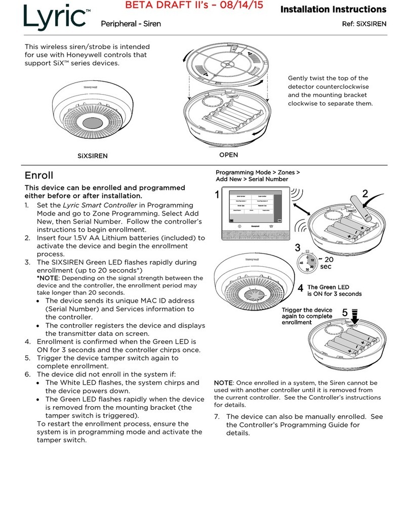
Honeywell Lyric SIXSIREN User manual

Honeywell
Honeywell Water Defense RWD41 User manual

Honeywell
Honeywell PROSiXSIRENO Assembly instructions
Honeywell
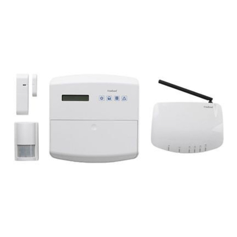
Honeywell Friedland HISK1 User manual

Honeywell
Honeywell Frieland FGGA06 Series User manual

Honeywell
Honeywell VISTA-128BP User manual

Honeywell
Honeywell GKP-S8M Setup guide

Honeywell
Honeywell AlarmNet 7845GSM User manual
Honeywell
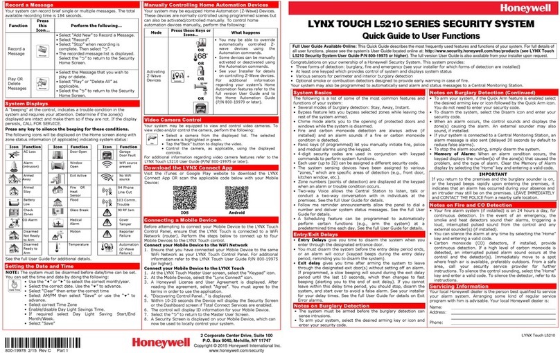
Honeywell LYNX Touch L5210 Series User manual

Honeywell
Honeywell NETAXS NX4L1 User manual

Honeywell
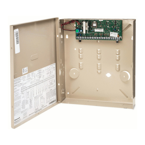
Honeywell Fire Lite Alarms SWIFT Datasheet
Honeywell
Honeywell Ademco Vista-48LA Assembly instructions

Honeywell
Honeywell Le Sucre User manual

Honeywell
Honeywell Galaxy Flex V3 Series User guide

Honeywell
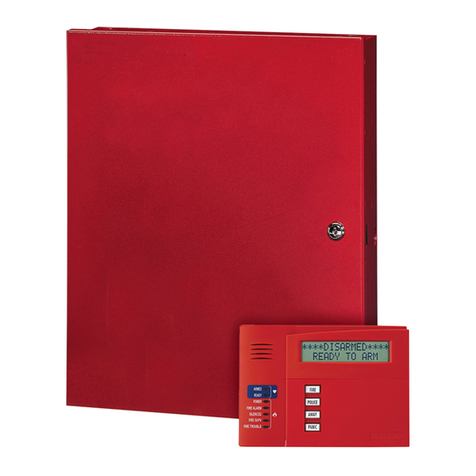
Honeywell Ademco VISTA-50PUL User manual
Honeywell
Honeywell VISTA-128FBPN Assembly instructions

Honeywell
Honeywell ADEMCO VISTA SERIES Operating instructions

Honeywell
Honeywell Ademco VISTA-20P User manual

Honeywell
Honeywell RCWL200A User manual
Popular Security System manuals by other brands

Inner Range
Inner Range Concept 2000 user manual

Climax
Climax Mobile Lite R32 Installer's guide

FBII
FBII XL-31 Series installation instructions

Johnson Controls
Johnson Controls PENN Connected PC10 Install and Commissioning Guide

Aeotec
Aeotec Siren Gen5 quick start guide

IDEAL
IDEAL Accenta Engineering information

Swann
Swann SW-P-MC2 Specifications

Ecolink
Ecolink Siren+Chime user manual

Digital Monitoring Products
Digital Monitoring Products XR150 user guide

EDM
EDM Solution 6+6 Wireless-AE installation manual

Siren
Siren LED GSM operating manual

Detection Systems
Detection Systems 7090i Installation and programming manual


