Hoppe 7517464 Service manual

Swing Door Service
Installation Packet
Paquete de servicio e
instalación de puerta
giratoria
Do Not Discard
Leave with Homeowner
No deseche
dejarlo con propietario
Part No. 7517464
N° de pieza 7517464

Page 2
Swing Door Handle Set
Installation Instructions
1. Apply the backplate gasket to the inside of the
exterior and interior backplates. Push gaskets rmly
into place to ensure a tight seal. Attach interior and
exterior backplates to the door and fasten loosely
with the screws provided. Note: The screw heads
must be on the interior side of the door.
2. Insert the two-piece handle shaft into one handle. Be
sure to orient the shaft as shown below. Screw the
set screw until ush with handle using the hex wrench
provided. Insert the handle with shaft attached
through the escutcheon plate and door gear handle
hole until extending out opposite side of door.
3. Install remaining handle onto shaft, pressing tightly
to the backplates. Tighten the handle set screw with
hex wrench. Screw until ush with handle.
4. Insert the keyed cylinder from the interior side of
the door until it is ush with the exterior backplate.
Install the cylinder screw in the screw hole below the
deadbolt in the edge of the door to secure in place.
5. Hand tighten the backplate screws to complete
assembly.
A Phillips screwdriver is required.
A 3mm hex wrench for set screws is
provided in the hardware package.
To prevent damage to the handle set
during the construction phase, use
the enclosed construction handle to
operate the door. Lift the handle to
engage the multipoints. Push down to
disengage.
Use water and a soft cloth to clean.
Do not use brass cleaner or solvent
based cleaning agents as they will
remove the protective coating on the
hardware.
Note: Handles and backplates vary by
style but application is the same.
See Cylinder Installation
Instructions for installing
cylinder
Exterior
Lever Handle
Exterior
Backplate
Gasket
Gasket
Interior of
Door Stile Construction
Handle
Interior
Backplate
Required Shaft
Position for Set
Screw
Cylinder Screw
(One Provided)
Backplate Screws
(Two ro Three Provided
Depending on the Backpaltes)
Interior Lever
Handle
Lock
Cylinder
Set Screw
(Two Provided)
Nylon
Bushing

Page 3
Juego de manilas de puerta giratoria
Instrucciones de instalación
Se requiere un destornillador Phillips.
Se proporciona una llave hexagonal
de 3mm para los tornillos de jación
en el paquete de tornillos.
Para evitar de danar la manilla
durante la fase de construcción,
utillice la manilla para construcción
que se incluye para abrir la puerta.
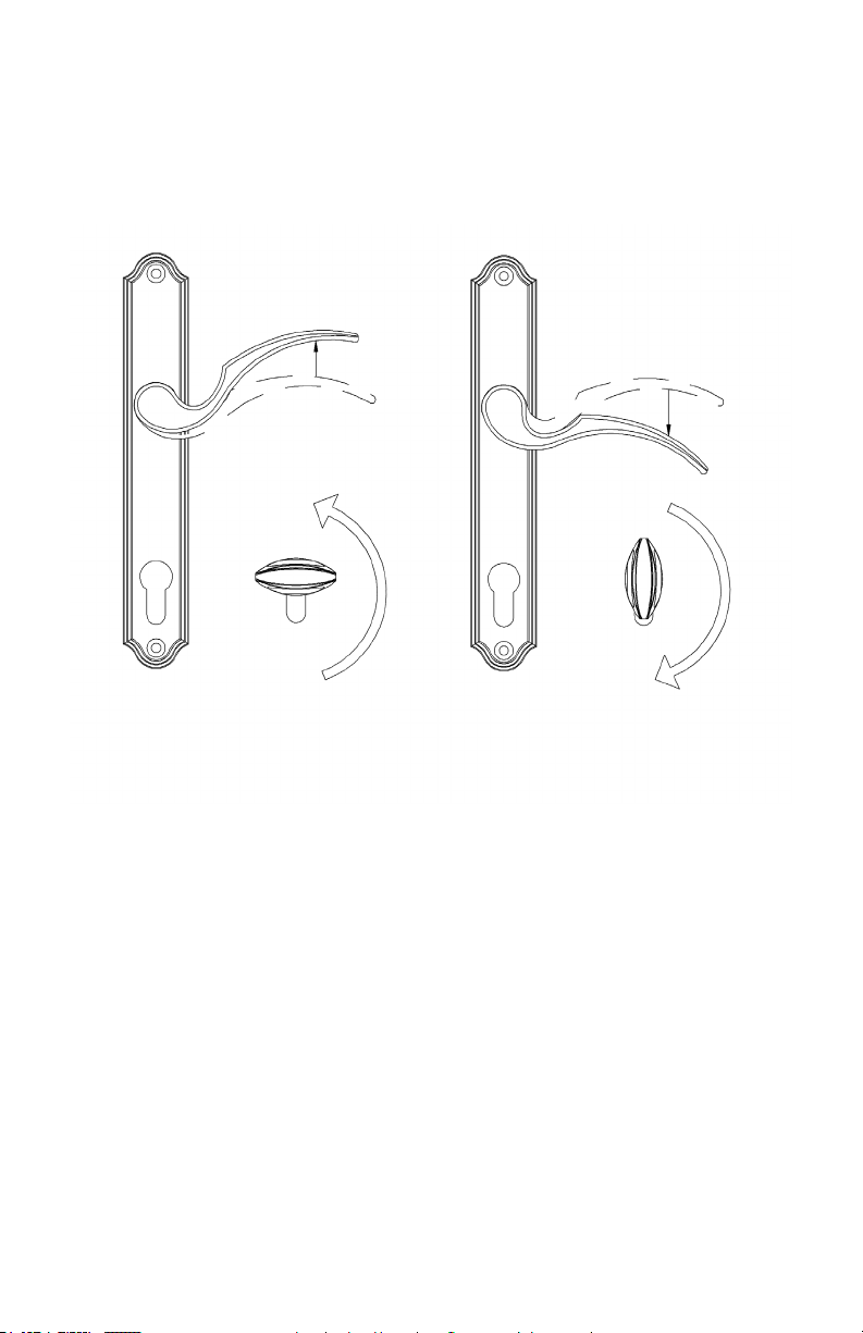
Levante la anilla para enganchar
las trabas multipunto con la puerta
cerrada. Empuje la manilla hacia
abajo para abrir a puerta.
Nota: Los estilos de las manillas y
placas de respaldo varian, pero su
uso es igual.
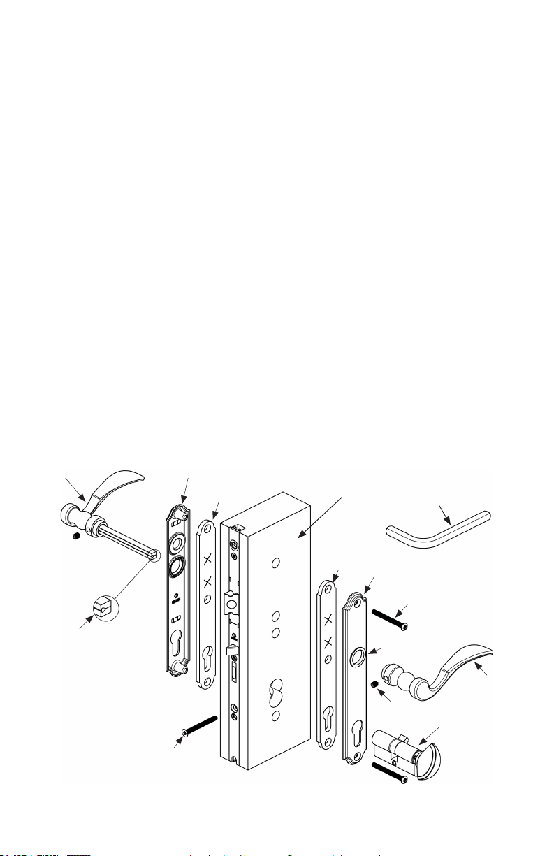
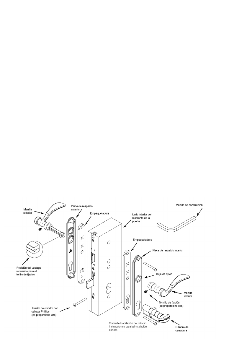
1. Coloque la empaquetadura de la placa de respaldo en
el lado interior de la placa de respaldo exterior. Empuje
la empaquetadura remente en su lugar para formas un
sello hermético. Coloque la empaquetadura de la placa
de respaldo en el lado interior de la placa de respaldo
interior. Coloque las placas de respaldo interior y
excterior y sujételas con los dos tornillos provistos sin
apretarios. Nota: Las cabezas de los tornillos deben
quedar orientadas hacia el lado interior de la puerta.
2. Inserte el vástago de dos piezas en la manilla.
Asegúrese de orientar el vástago como se muestra en
la ilustración siguiente. Enrosque el tornillo de fjación
hasta que quede a ras con la manilla usando la llave
Allen. Inserte la manilla en el agujero del pestillo.
3. Instale la manilla interior en el vástago, a través del
agujero del pestillo, oprimiéndola adjustadamente contra
las placas de respaldo. Apriete el tornillo de fjación de la
manilla interior usando la llave Allen. Enrósquelo hasta
dejarlo a ras con la manilla.
4. Inserte el cilindro congurado para la llave por el lado
interior de la puerta hasta que quede a ras con la placa
de respaldo exterior. Instale el tornillo del cilindro en el
agujero que está debajo del cerrojo, en el borde de la
puerta. Apriete los tornillos de la placa de respaldo.
5. Apriete los tornillos de la placa de respaldo

Page 4
Swing Door Handle
Operation Instructions
Handle and backplates vary in style
To lock a manual system, lift the handle to
engage the multi-points before engaging the
deadbolt.
Gradually return the handle to the home
position. Do not abruptly release the handle.
Releasing the handle abruptly will cause the
handle to spring back beyond the home
position causing partial retraction of the multi-
points. When this happens, the deadbolt
cannot be extended.
Use the a key or the thumbturn to engage the
deadbolt after the multi-points are engaged.
To open both automatic and
manual systems, disengage
the deadbollt with a key or the
thumbturn, push the handle
down until multi-points are
retracted, and then open door.
Manual System
Automatic System
To lock an automatic system, push the door shut. Multi-points will engage
automatically when the auto-release pin hits the strike plate mounted on the jamb.

Page 5
Los estilos de las manillas y placas de respaldo varían
Instrucciones de uso
de la manilla de puerta giratoria
Si el cerrojo no se engancha completamente,
enganche el sistema manualmente
levantando la manilla antes de enganchar el
cerrojo.
Gradualmente devuelva la manija a
la posición inicial. No suelte la manija
abruptamente. Soltando la manija
abruptamente puede causar que la manija
resalte sobre la posición inicial, y podrá
causar retracción parcial de los multipuntos.
Cuando esto sucede, el cerrojo no se puede
extender.
Use la tecla o el botón giratorio para activar el
cerrojo después de activar los multipuntos.
Para abrir la puerta, desenganche el
cerrojo con la llave o el pasador de
giro, empuje la manilla hacia abajo
hasta su tope y luego abre la puerta.
Sistema Manual
sistema automático
Para atrancar el sistema automático, empuje la puerta hasta cerrarla. Las trabas multipunto se
enganchan automáticamente.

Page 6
PLEASE NOTE: MAIN GEAR AND EXTENSIONS SHOULD BE HAND-TIGHTENED ONLY.
EXCESSIVE FORCE MAY CAUSE DRIVE RAIL TO BIND AND INHIBIT SYSTEM OPERATION.
1. With the door in the open position, the bevel on the latch should slide into the strike plate
for the latch and deadbolt door as you close the door. If you need to reverse the latch, see
Hardware Adjustment Sheet also see page 14.
2. Slide main gear (shown in drawing) into place aligning holes drilled in door face with cylinder,
handle holes and lockcase to properly accommodate trim. Ensure that the operating gear is
ush with the wood edge style of the door, reference page 2.
3. Install handle set per Swinging Patio Door Handle Set Installation Instructions.
4. Remove machine screw in top of lockcase. Top drive rail needs to connect to linkage in gear
lockcase. Slide top extension into place and fasten to lockcase with the supplied machine
screws to door edge. Use #7 screws. The #7 stainless steel screws should be screwed in
ush with the faceplate, but not over tightened. See page 14 for drive rail and gear alignment.
Test gear with the door in the open position. Engage system by depressing mishandling
device and lifting handle (note if multipoint system operates on the edge of the door) and
extend deadbolt by turning thumbturn. If the system operates freely on the door edge and the
deadbolt operates, the hardware system in the door is fully functional. If not, please see the
Troubleshooting Guide on page 10 and 11.
PLEASE NOTE: MAIN GEAR AND EXTENSIONS SHOULD BE HAND TIGHTENED ONLY.
EXCESSIVE FORCE MAY CAUSE DRIVE RAIL TO BIND AND INHIBIT SYSTEM OPERATION.
Installation of Multipoint
Swing Door Hardware

Page 7
TENGA EN CUENTA: engranaje y extensión debe ser apretada a mano solamente.
UNA FUERZA EXCESIVA lata unirse e inhibir el funcionamiento.
1. Con la puerta en la posición abierta, el bisel del pestillo debe deslizarse hacia la placa de
cierre para la puerta del pestillo y el pestillo al cerrar la puerta. Si necesita invertir el pestillo,
consulte la Hoja de ajuste de hardware también en la página 15.
2. Deslice el engranaje principal (que se muestra en el dibujo) en su lugar alineando los oricios
taladrados en la cara de la puerta con el cilindro, los oricios de las manijas y la caja de
bloqueo para acomodar adecuadamente el borde. Asegúrese de que el engranaje de
operación esté alineado con el estilo de borde de madera de la puerta, consulte la página 3.
3. Instale el juego de manillas según lo indicado en las instrucciones de instalación del juego de
manillas para puertas giratorias de patio.
4. Retire el tornillo de la máquina en la parte superior de la caja de seguridad. El riel de
transmisión superior debe conectarse al enlace en la caja de engranajes. Deslice la extensión
superior en su lugar y fíjela a la caja con los tornillos para metales suministrados al borde de
la puerta. Use tornillos # 7. Los tornillos de acero inoxidable n. ° 7 deben atornillarse a ras
de la placa frontal, pero no apretarse demasiado. Consulte la página 14 para ver el riel de
transmisión y la alineación del engranaje. Pruebe el engranaje con la puerta en la posición
abierta. Enganche el sistema presionando el dispositivo de mal manejo y levantando la manija
(observe si el sistema multipunto opera en el borde de la puerta) y extienda el cerrojo girando
la palanca. Si el sistema funciona libremente en el borde de la puerta y el cerrojo funciona, el
sistema de hardware en la puerta es completamente funcional. De lo contrario, consulte la
Guía de solución de problemas en las páginas 12 y 13.
FAVOR DE OBSERVAR: EL MECANISMO PRINCIPAL Y LAS EXTENSIONES DEBEN APRETARSE
CON LA MANO SOLAMENTE. EL USO DE FUERZA EXCESIVA PUEDE HACER QUE EL RIEL
IMPULSOR SE ATORE E IMPEDIR QUE EL SISTEMA FUNCIONE.
Instalación de cerraduras
multipunto para puerta giratoria

Page 8
HLS9000 Multipoint Hardware
System Terminology
Note:
All options are shown for the sake of terminology.
The gear system you have will NOT contain all of
the components as shown in the diagram below.
TERMINOLOGY:
1. Top Shootbolt (Pinions
for reverse action in Circle)
2. Bottom Shootbolt
3. Deadbolt
4. Mishandling Device
5. Latch Bolt
6. Cylinder Hole
7. Handle Hole
8. Lockcase
9. Drive Rail
10. Faceplate
11. Screw Support
12. Tongue
13. Roller
14. Auto-Release Pin
15. Top Extension Phillips
Machine Screw
16. Roundbolt
17. Swing Hook
1. Trim Maintenance:
Use water to clean and a soft cloth. Do not use brass cleaner as it will remove the
protective coating.
2. Prole Cylinder:
Cylinders are available in rekeyable Schlage C version. Key blanks are available at most
hardware stores

Page 9
Nota:
Se ilustran todas las opciones para nes de terminología.
Un sistema particular NO incluye todos los componentes
que se muestran en el diagrama abajo.
Terminología del sistema
de equipo multipunto HLS9000
TERMINOLOGÍA:
1. Cerrojo superior (Piñones para
acción inversa en círculo)
2. Cerrojo de fondo
3. Cerrojo
4. Dispositivo contra intrusión
5. Pestillo
6. Agujero del cilindro
7. Agujero de manilla
8. Caja de cerradura
9. Riel impulsor
10. Placa de sujeción
11. Soporte de tornillo
12. Lengua
13. Rodillo
14. Clavija de soltado automátic
15. Tornillo Phillips de rosca na de
extensión superior
16. Perno redondo
17. Gancho de columpio
1. Mantenimiento de piezas decorativas:
Limpie con agua y un trapo suave. No use productos limpiadores de latón ya que éstos
quitan el revestimiento protector.
2. Cilindro de perl:
Los cilindros se ofrecen en la versión con llave modicable en las bocallaves Schlage C
clavijas. Las llaves vírgenes se pueden obtener en la mayoría de las ferreterías comunes.

Page 10
Be certain door is square in frame before adjusting other hardware. With the door in the
open position, engage system by lifting handle and extend deadbolt by turning thumb
turn. If the system operates on the door edge and the deadbolt operates, the hardware
system is fully functional.
1. SYSTEM WILL NOT OPERATE WHEN YOU LIFT THE HANDLE
Probable Cause: Improper installation of handle set.
Solution: Remove handle and reinstall. See Handle Set Installation Instructions.
2. SYSTEM OPERATES IN THE OPEN POSITION WHEN YOU LIFT THE HANDLE BUT
NOT IN THE CLOSED POSITION WITH THE DOOR SHUT
Probable Cause: Relationship of door in the frame.
Solution: Check to make sure the door is square in the frame.
Probable Cause: If automatic version, the auto release pin may not be adjusted properly.
Solution: See Hardware Adjustment Sheet.
3. LOCKING POINTS WILL NOT ENGAGE WITH DOOR SHUT
Probable Cause: Deadbolt is not fully extending.
Solution: Clear away anything blocking travel of deadbolt (insulation, wood, etc.).
4. DEADBOLT WILL NOT FULLY ENGAGE
Probable Cause: Locking points are not fully engaged. System design does not permit
deadbolt operation unless locking points are fully engaged.
Solution: Check system again for binding problems. Conrm deadbolt extends fully
into strike. Check to conrm locking points are correctly engaging strikes on the frame.
5. THUMBTURN OR KEY WILL NOT TURN
Probable Cause: Backplates may not be on straight.
Solution: Conrm that inside and outside holes line up with lockcase. Loosen
backplate screws ½ turn.
Troubleshooting Guide
Multipoint Swing Door Hardware

Page 11
6. HANDLE SAGS OR RETURNS SLOWLY
Probable Cause: Cladding or wood in the hole is interfering with shaft.
Solution: Check to see if machined holes line up with screw and handle holes. May
need to le or drill hole slightly larger.
7. SET SCREWS WILL NOT GO INTO HANDLE COMPLETELY
Probable Cause: Shaft is not assembled properly.
Solution: Remove handle to see how shaft is assembled. See Handle Set Installation
Instructions for proper assembly and position of shaft.
8. BOTTOM LOCKING POINT MOVES BUT TOP LOCKING POINT DOES NOT
Probable Cause: Top extension drive rail is not connected at the lockcase.
Solution: Remove screws used to attach top extension to the door and the machine
screw that attaches it to the lockcase, and remove top extension. Place the end of
the drive rail (the “L” shape) in the lockcase above the latchbolt, as you slide the top
extension into the door. Fasten with a screw at the lockcase and the one up higher.
Operate the gear to make sure it works. Then nish installing the rest of the screws.
9. IF DOOR HAS PLAY OR IS NOT SEALING CORRECTLY
Probable Cause: Unit is not adjusted properly.
Solution: Bend tab on strike.
Solution: If available adjust Roller (See Adjustment Instructions)
Solution: If available adjust Hinge
10. KEY DOES NOT WORK IN CYLINDER
Probable Cause: Cylinder was rekeyed incorrectly.
Solution: Check with Builder or Installer to see if cylinder was rekeyed to match other
doors in the house. If so, return to locksmith to rekey properly.

Page 12
Compruebe que la puerta esté a escuadra en su marco antes de ajustar otros
elementos. Con la puerta en posición abierta, accione el sistema levantando la manilla
y extienda el cerrojo girando el pasador de giro. Si el sistema funciona en el orilla de la
puerta y el cerrojo funciona bien, el equipo funciona completamenta.
1. SI EL SISTEMA NO FUNCIONA CUANDO SE LEVANTA LA MANILLA
Causa probable: Instalación incorrecta del juego de manillas.
Solución: Retire la manilla y vuélvala a instalar. Consulte las instrucciones de instalación
del juego de manillas.
2. SI EL SISTEMA FUNCIONA CON LA PUERTA ABIERTA CUANDO SE LEVANTA LA
MANILLA PERO NO FUNCIONA CON LA PUERTA CERRADA
Causa probable: relacion de marco de la puerta.
Solución: Comprobar que la puerta esté a escuadra en el marco.
Causa probable: Si la cerradura es de versión automática, la clavija de soltado
automático podría no estar debidamente ajustada.
Solución: Comprobar la hoja de ajuste de la cerradura.
3. SI LOS PUNTOS DE TRABA NO SE ENGANCHAN CON LA PUERTA CERRADA
Causa probable: El cerrojo no se extiende completamente.
Solución: Despejar cualquier viaje bloqueo de cerrojo (aislamiento, madera, etc.).
4. SI EL CERROJO NO SE ENGANCHA COMPLETAMENTE
Causa probable: Los puntos de traba no se enganchan completamente. El diseño del
sistema no permite que el cerrojo se accione a menos que los puntos de traba estén
completamente enganchados.
Solución: Vuelva a revisar el sistema en busca de atascamiento. Verique que el cerrojo
se extienda completamente dentro del cerradero. Compruebe que los puntos de traba
se enganchen correctamente en los cerraderos del marco.
5. SI NO ES POSIBLE GIRAR EL PASADOR DE GIRO O LA LLAVE
Causa probable: Las placas de respaldo posiblemente no están derechas.
Solución: Verique que los agujeros interiores y exteriores estén alineados con la caja de
la cerradura. Suelte los tornillos de la placa de respaldo 1/2 vuelta.
Guía para la localización de
averías Cerradura multipunto
para puerta giratoria

Page 13
6. SI INTERFERENCIA DE PUERTA CON LA MANILLA
Causa probable: El revestimiento o madera en el agujero interere con el vástago.
Solución: Verique que los agujeros taladrados estén alineados con los agujeros
de tornillos y de la manilla. Puede tener que presentar o taladar agujero un poco
masgrande.
7. SI LOS TORNILLOS DE FIJACIÓN NO PENETRAN EN LA MANILLA COMPLETAMENTE
Causa probable: El vástago no ha sido armado debidamente.
Solución: Quite la manilla para ver cómo se ha armado el vástago. Consulte las
instrucciones de instalación del juego de manillas para el armado y posición correctos
del vástago.
8. SI EL PUNTO DE TRABA INFERIOR SE MUEVE PERO EL PUNTO DE TRABA
SUPERIOR NO
Causa probable: El riel impulsor de la extensión superior no está conectado con la caja
de la cerradura.
Solución: Saque los tornillos que se usan para jar la extensión superior a la puerta y
el tornillo de rosca na que la ja a la caja de la cerradura y retire la extensión superior.
Coloque el extremo del riel impulsor (con forma de un “L”) en la caja de la cerradura,
encima del pestillo, mientras se desliza la extensión superior dentro de la puerta.
Fíjelo con un tornillo a la caja de la cerradura y con el tornillo más arriba. Accione el
mecanismo para vericar que funciona. Después termine de instalar el resto de los
tornillos.
9. SI LA PUERTA TIENE JUEGO O NO SE SELLA CORRECTAMENTE
Causa probable: La unidad no está debidamente ajustada.
Solución: Doble pestana en huelga.
Solución: Si el rodillo de ajuste disponibles (Vea las Instrucciones de ajuste)
Solución: Si bisagra de ajuste disponible
10. SI LA LLAVE NO FUNCIONA EN EL CILINDRO
Causa probable: El cilindro no esta se reconguró correctamente para la llave.
Solución: Consulte con el constructor o con el instalador para ver si se cambió la
conguración de la llave del cilindro para que correspondiera con las demás puertas de
la casa. En tal caso, devuelva la cerradura al cerrajero para que la congure para la llave
correcta.

Page 14
Hardware Modication
Instruction Sheet
Reversing Mishandling
Device in Field:
1. Remove shipping clip
2. Make sure mishandling
device is sloped the
same as latch.
3. If not, pull out and
spin180* to the same
direction.
Reversing Mishandling
Device in Factory:
1. Remove shipping clip
2. Pull out mishandling
device to spin to slope
the same as latch.
3. Push mishandling
device in and snap
shipping clip back in.
Shipping Clip for
Mishandling Device
Attaching Top Extension
Pull and rotate latch 180* with
hand and release back into
the lockcase.
A
Hook drive rail of top extension
into gear linkage just above latch.
Screw machine screw through
top extension into screw boss.
Reversing Latch
Angled surfaces on Latch and
Mishandling Device needs to
be in a matching directions

Page 15
Hoja de instrucciones de
modicación de cerradura
Clip del envío para el mal
manejo de dispositivos Fijación
A
1. Quite clip de plástico
negro
2. Asegúrese de aparato
mal manejo está inclinado
mismo como el pestillo.
3. En caso contrario, extráigalo
y girelo 180° para orientarlo
en el mismo sentido.
Inversion del dispositivo contra
intrusion en el campo:
Inversion del dispositivo contra
intrusion en el fábrica:
1. Quite Ia etiqueta
2. Quite clip de plástico negro.
3. Asegúrese de aparato
mal manejo está inclinado
mismo como el pestillo.
4. En caso contrario, extráigalo
y girelo 180° para orientarlo
en el mismo sentido.
5. Empuje el aparato mal
manejo dentro de el
lockcase
Hook riel de unidad de extensión
superior en engranaje de justo por
encima del el pasador.
Atornille el tornillo de la máquina a
través de la extensión superior en
el saliente del tornillo.
Revertir Latch
Jale girar el pestillo 180 *
con la mano y suelte de
nuevo en el lockcase.
Las supercies anguladas en el
dispositivo de enganche y mal
manejo deben estar en direcciones
coincidentes

Page 16
REMOVAL TOOL
for PLASTIC
INSERT
2 mm or 5/64”
HEX WRENCH P/N
7065774
(for use with no-logo
cylinders)
PLASTIC INSERT
Part Number
8771719
(for use with CES
cylinders)
KEY GAUGE
Not oered by
HOPPE
Recommended Tools and Accessories
HOPPE REKEY KITS
Schlage® Pins, 30 cyl.
capacity
- P/N 3459001
• Rekeying should be done by a qualied
locksmith.
• Cylinder designs vary. HOPPE supplies CES
brand cylinders and non-logo cylinders.
• Cylinders feature Schlage® SC1 keyways
and may be rekeyed using Schlage® rekey
kits.
• Cylinders should be rekeyed to an existing
Schlage® key whenever possible.
• The HOPPE key gauge measures key cuts
1 through 9 the same as a Schlage® key
gauge.
• If rekeying a CES cylinder with CES pins, use
the CES pin number that corresponds with the
measured key cut.
• If rekeying a CES cylinder with Schlage® pins,
use the Schlage® pin number that is one less
than the measured key cut. A key cut measur-
ing 4 uses a #3 Schlage® pin.
• If rekeying a non-logo cylinder with Schlage®
pins, then use the Schlage® pin number that
corresponds with the measured key cut.
• If rekeying a non-logo cylinder with CES pins,
use the CES pin number that is one higher than
the measured key cut. A key cut measuring 4
uses a #5 CES pin.
HOPPE Prole Cylinders
Rekeying Instructions
Steps to Rekey
Remove PLASTIC INSERT using
REMOVAL TOOL as shown and
tap out PINS and SPRINGS
Remove one SET SCREW at a time
using 2 mm HEX WRENCH as shown
and tap out PINS and SPRING
1.
3.
2. Determine CORE PIN size with KEYING GAUGE
Contact your local hardware store or search the
Internet for “Schlage Key Guage”.
• Insert desired CORE PIN into the appropriate
cylinder pin hole.
• Note: for cylinder designs featuring six pin
holes, the innermost hole (furthest from
the key face) is left blank.
• Insert HOUSING PIN
• Insert SPRING
• Repeat until all PINS have been replaced and
install PLASTIC INSERT OR install SET SCREW
and repeat until all PINS have been replaced.
Visit HOPPE North America on YouTube to see a cylinder removal video and other helpful videos.
1-888-485-4885 www.hoppe.com
P/N 7517355
p1312012e065
Introduction

Page 17
Cilindros de perl HOPPE
Rekeying Instrucciones
• Si vuelve a crear claves de un cilindro CES con
alleres Schlage ®, utilice el número pin Schlage
®, que es uno menos que el corte clave medido.
Un corte tecla de medición 4 utiliza un pin # 3
Schlage ®.
• Si vuelve a crear claves de un cilindro no-logo
con Schlage ® alleres, a continuación, utilice el
número de pin Schlage ® que se corresponde
con el corte clave medido.
• Si vuelve a crear claves de un cilindro no-logo con
los pernos de la CES, utilice el número pin CES,
que es uno más alto que el corte clave medido.
Un corte tecla de medición 4 utiliza un pin # 5
CES.
• Rekeying debe ser realizado por un cerrajero
cualicado.
• Cilindro diseños muy. HOPPE suministra cilindros
marca CES y cilindros sin logo.
• Los cilindros cuentan con Schlage ® SC1 chavetas y
pueden rekeyed utilizando kits Schlage ® rekey.
Los cilindros deben ser rekeyed a un Schlage ®
existente llave siempre que sea posible.
• El indicador clave HOPPE mide muescas de llave
1 hasta el 9 de la misma como un indicador clave
Schlage ®.
• Si vuelve a crear claves de un cilindro con pernos
CES CES, utilice el número pin CES que se
corresponde con el corte clave med
Introducción
Pasos para Rekey
Herramientas y Accesorios recomendados
HERRAMIENTA DE
DESMONTAJE para
INSERTOS DE PLÁSTICO
LLAVE HEXAGONAL
DE 2 mm O 5/64 ”P / N
7065774
(para usar con
cilindros sin logotipo)
Determine el tamaño del PIN CORE con KEYING GAUGE
Póngase en contacto con su ferretería local o busque el
Internet para “Schlage Key Guage”.
Retire una TORNILLO a la vez
con le 2 mm LLAVE HEXAGONAL
como se muestra y toque los
pasadores y la primavera
HOPPE Rekey KITS
Clavijas Schlage ®, 30 cil.
capacidad
- Número de pieza 3459001
MEDIDOR CLAVE
No ofrecido por
ESPERANZA
INSERCION PLASTICA
Número de pieza
8771719
(para usar con cilindros
CES)
3.
2.
1. Retire PIEZA DE PLÁSTICO
INSERTO usando la HERRAMIENTA
eliminacion como se muestra y
toque los pasadores y resortes
tornillos de
jación
Resortes
Caja
Clavijas
de cilindro
(inferiores)
OR
nserto de
plástico
Resortes
Caja
Clavijas
de cilindro
(inferiores)
OR
• Poner PIN BASE deseada en el oricio del
pasador de cilindro adecuado.
Nota: para los diseños de cilindros con seis
oricios, el agujero más profundo (más de la
faz de llave) se deja en blanco.
• Introduzca PIN VIVIENDA
• Inserte PRIMAVERA
• Repita hasta que todos los pasadores
han sido sustituidos e instalar INSERT
PLÁSTICO O Instale el tornillo y repita hasta
que todas PINS han sido reemplazados.
Visite HOPPE North America en YouTube para ver un video de extracción de cilindros y otros videos útiles.

Page 18
Tools required:
Phillips head screw driver
Hex wrench (provided)
Ring wrench (provided)
Pliers (recommended)
Installation:
1. Loosen set screw (C) on knob (D) using the hex wrench provided. Knob designs may vary from
design shown.
2. Remove knob (D) from body of cylinder (B).
3. Align drive tab (J) with the cylinder body to install the cylinder into the lock as shown by (G). If the
drive tab (J) cannot be rotated to this position, push the pin (E) down with the ring wrench (F) to
disengage the stops and turn the cylinder shaft (B) until the drive tab (J) is aligned with the cylinder as
shown by (G).
4. Holding the cylinder in this position, insert the cylinder body into the lock so the drive tab (J) is inside
of the lock.
5. Rotate the shaft (B) (use pliers if necessary) so the top of the shaft (B) moves toward the edge of the
door or insert the key (A) into the cylinder and rotate so the top of the key (A) moves towards the
edge of the door (H). The shaft or key will rotate freely and will stop after approximately 120°. Do
not force rotation. The dead bolt should not extend (exception: dead bolt will extend on single point
gear). Conrm that one of the two set screw openings is positioned on the bottom of the shaft (B).
Warning: If the shaft (B) or key (A) is rotated the wrong direction, the cylinder will lock after
approximately 120° and cannot be rotated in either direction. If this happens, push the pin
(E) down with the ring wrench (F) included to disengage the stops and turn the shaft (b) or
key (A) in the opposite direction until the dead bolt extends.
6. Attach knob (D) on shaft (B) as shown.
7. Tighten set screw (C). Install cylinder screw (K) as shown.
Removal:
1. Loosen and remove cylinder screw (K) and repeat steps 1-4 above.
Installation Instructions
90-Degree Turn Cylinder
(A) (B)
(B)
(B)
(C)
(C)
(D)
(D)
(E)
(F)
(G)
(H)
(H)
(J)
(K) (A)
Aligned

Page 19
Herramienta que necesita:
Destornillador Phillips
Llave hexagonal (provista)
Llave del anillo (suministrada)
Alicates (recomendados)
Instalación:
1. Aoje el tornillo de jación (C) en el mando (D) usando la llave hexagonal provista. Diseños de perilla
pueden variar de diseño que se muestra.
2. Quite el mando (D) del cuerpo del cilindro (B).
3. Alinee la unidad lengüeta (J) con el cuerpo del cilindro para instalar el cilindro en la cerradura como se
muestra en (G). Si la cha del coche (J) no puede ser girada a esta posición, empuje el pasador (E)
hacia abajo con la llave del anillo (F) para desenganchar las paradas y gire el eje del cilindro (B) hasta
que la cha de unidad (J) esté alineada con el cilindro como se muestra (G).
4. Sosteniendo el cilindro en esta posición, inserte el cuerpo del cilindro en la cerradura para que la cha
de unidad (J) está dentro de la cerradura.
5. Gire el eje (B) (use pinzas si es necesario) para la parte superior del el eje (B) se mueve hacia el borde
de la puerta o inserte la llave (A) en el cilindro y gire hasta que la parte superior de la llave (A) se
mueve hacia el borde de la puerta (H). El eje o el clave girará libremente y se detendrá después de
aproximadamente 120°. No fuerce la rotación. No debe extenderse el pestillo (excepción: cerrojo se
extenderá en el engranaje monopunto). Conrman que uno de los dos oricios de tornillo se coloca
en la parte inferior del eje (B).
AVISO: Si se hace girar el eje (B) o la tecla (A) la dirección equivocada, el cilindro se
jará después de aproximadamente 120° y no puede girarse en cualquier dirección. Si
esto sucede, presione el pasador (E) hacia abajo con la llave del anillo (F) incluida para
desenganchar las paradas y gire el eje (b) o la tecla (A) en la dirección opuesta hasta que el
pestillo se extiende.
6. Fije en el mando (D) en el eje (B) como se muestra.
7. Apriete el tornillo de jación (C). Instale el cilindro tornillo (K) como se muestra.
Retiro:
1. Aoje y retire el cilindro tornillo (K) y repita los pasos 1-4 arriba.
Instrucciones de instalación
Cilindro de giro de 90 grados
(A) (B)
(B)
(B)
(C)
(C)
(D)
(D)
(E)
(F)
(G)
(H)
(H)
(J)
(K) (A)
Alineado

Page 20
• Se requiere una llave hexagonal de 4 mm o 5/32”
Una llave hexagonal de 4 mm o 5/32” es Esta instrucción se aplica a los sistemas de bloqueo
multipunto HOPPE® HLS Roller. Los bloqueos multipunto de rodillo HOPPE cuentan con
capacidad de ajuste para proporcionar una compresión óptima del sello del tiempo. Esto
permite ajustes de +/- 1 mm que proporcionan compresión adicional del sello del tiempo o un
funcionamiento de bloqueo mejorado.
1. En la cara del punto de bloqueo del rodillo, localice el indicador posicional.
Una posición a las 3:00 indica la posición más a la derecha.
Una posición de las 9:00 indica la posición más a la izquierda.
Una posición de las 12:00 en punto indica la posición más alta.
Una posición de las 6:00 en punto indica la posición más baja.
1. Con la llave hexagonal, gire el indicador posicional para aumentar o disminuir la compresión
del sello meteorológico.
2. Repita el ajuste para los puntos de bloqueo del rodillo
restantes como desee.
3. Cierre la puerta y enganche los rodillos para probar los
ajustes.
4. Los ajustes pueden resultar en una sobrecompresión del
sello meteorológico que causa una operación de bloqueo
difícil. Vuelva a ajustar los rodillos para reducir la compresión del sello meteorológico cuando la
operación de bloqueo no es deseable.
Adjustment Instructions
Roller Multipoint
• A 4 mm or 5/32” hex wrench is required
This instruction applies to HOPPE® HLS Roller Multipoint locking systems. HOPPE Roller Multipoint
locks feature adjustability to provide optimal weather seal compression. This allows for +/- 1
mm adjustments that provide additional weather seal compression or improved lock operation.
1. On the face of the Roller lock point, locate the positional indicator.
A 3:00 o’clock position indicates the rightmost position.
A 9:00 o’clock position indicates the leftmost position.
A 12:00 o’clock position indicates the highest position.
A 6:00 o’clock position indicates the lowest position.
2. Using the hex wrench, turn the positional indicator to increase
or decrease weather seal compression.
3. Repeat the adjustment for the remaining Roller lock points as
desired.
4. Close the door and engage the Rollers to test the
adjustments.
5. Adjustments may result in over-compression of the weather
seal causing dicult lock operation. Re-adjust Rollers to reduce weather seal compression
when lock operation is undesirable.
Positional Indictor
Indictora Posicional
Instrucciones de ajuste
Roller Multipoint
Table of contents
Languages:
Other Hoppe Door Lock manuals
Popular Door Lock manuals by other brands

Kaba
Kaba 5 00 Series installation instructions

Schlage
Schlage Dexter JD60 installation guide

UNIVERSAL HARDWARE
UNIVERSAL HARDWARE UH4051 installation instructions

CAMDEN
CAMDEN CX-ED1259-L installation instructions

SDC
SDC Z7835 Series installation instructions

Coastal Bronze
Coastal Bronze 50-100 installation instructions