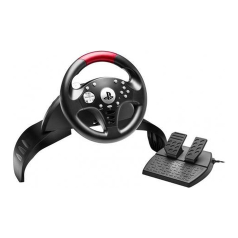
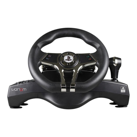
HORI RACING WHEEL PRO DELUXE User manual

1
・Gyroscope ・Accelerometer ・IR Motion Camera ・Player LED
・HD Rumble ・HOME Button Notification LED・NFC
* This controller works only in TV Mode.
* Make sure that your Nintendo Switch™ is updated with the latest system software.
* This product does not support the following features:
Instruction Manual
RACING WHEEL PRO DELUXE
for Nintendo Switch™ / PC
Thank you for purchasing this product.
Before using this product, please read the instructions carefully.
After reading the instruction manual, please keep it for reference.
EN
Assign Mode 12-13
Main Features 14
ITEM Button Hold Function 13
Quick Handling Mode 11
Adjustable Dead Zone 10
Adjustable Sensitivity 9
Reset Back to Default Settings 11
Directional Pad Control Toggle Switch 11
Caution 3
Included 4
Compatibility 4
Layout and Features 5
How to Set Up
Steering Unit
Foot Pedals
6-7
How to Connect 8
2-3
Product Setup
Table of Contents
https://stores.horiusa.com/nsw-429U/compatibility/
Compatible Software

Product Setup
Make sure that your Nintendo Switch™ is updated with the latest system software.
1
From the Home Menu select ‘Settings’.
Select ‘System’ and then ‘System Update’ to update to the
latest system software.(Please skip this step if console
already has the latest system software.)
Mount the steering unit onto a flat, stable surface.
2
Steering Unit
⇒p.6~7
Foot Pedals
⇒p.7
2

Connect all of the cables accordingly.
3
How to Connect
⇒p.8
Turn the steering wheel fully to the right, then fully to the left.
(This ensures proper wheel calibration.)
2
1
Caution Parents/Guardians:
Please read the following information carefully.
●
●
●
●
●
●
●
●
●
●
●
●
●
●
●
●
●
●
This product contains small parts. Keep away from children under 3 years old.
Keep this product away from small children or infants. Seek medical attention immediately if any small parts are swallowed.
Long cord. Strangulation hazard.
Keep the product away from dusty or humid areas.
Do not use this product if it has been damaged or modified.
Do not get this product wet. This may cause an electric shock or malfunction.
Do not place this product near heat sources or leave under direct sunlight for an extended period. Overheating may cause
malfunction.
Do not use this product with a USB hub. The product may not function properly.
Do not touch the metal parts of the USB plug.
Do not apply strong impact or weight on the product.
Do not pull roughly or bend the cable of the product.
Do not disassemble, modify or attempt to repair this product.
If product needs cleaning, use only a soft dry cloth. Do not use any chemical agents like benzene or thinner.
The wires are not to be inserted into socket-outlets.
The packaging must be retained since it contains important information.
The normal function of the product may be disturbed by strong electro-magnetic interference. If so, simply reset the product to
resume normal operation by following the instruction manual (How to Connect). In case the function does not resume, please
relocate to an area which does not have electro-magnetic interference to use the product.
Do not use this product for anything other than its intended purpose. We are not responsible for any accidents or damages in the
event of use other than the intended purpose.
Keep your fingers away from the foot pedals during gameplay.
3
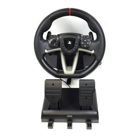
Included
Foot Pedals × 1Steering Unit × 1
Screw × 1Clamp × 1 Instruction Manual × 1
Compatibility
Nintendo Switch™
Nintendo Switch™ – OLED Model
* Functions as PC controller through XInput. This product does not support DirectInput.
PC (XInput)
* An Internet connection is required to update the Nintendo Switch™ to the latest system software.
Important
Please be sure to read the instruction manual for the Nintendo Switch™ before using the product with the
Nintendo Switch™. Make sure that your Nintendo Switch™ is updated with the latest system software.
Windows®11 / 10
XInput
USB Port (Type-A)
Supported OS
Input Method
System Requirements
4

Layout and Features
Steering Unit
Foot Pedals
R Pedal (A Button)
PC : R Pedal (RT Button)
L Pedal (B Button)
PC : L Pedal (LT Button)
Modular Plug
Pedal Cable Cable Groove
Capture Button
PC : N/A
Directional Pad
PC : Directional Pad
- Button
PC : BACK Button
ZL Button
PC : LT Button
L Stick Button
PC : L Stick Button
ASSIGN Button
LED (L)
Steering (L Stick X Axis)
PC : Steering (L Stick X Axis)
ITEM Button (ZL Button)
PC : ITEM Button (LT Button)
When playing Mario Kart™ 8 Deluxe ⇒p.13
R Stick Button
PC : R Stick Button
ZR Button
PC : RT Button
X Button
PC : X Button
Y Button
PC : Y Button
+ Button
PC : START Button
LED (R )
A Button
PC : A Button
B Button
PC : B Button
HOME Button
PC : GUIDE Button
Directional Pad Control Toggle Switch
R Paddle (R Button)
PC : R Paddle (RB Button)
L Paddle (L Button)
PC : L Paddle (LB Button)
Foot Pedal Connection
Controller Cable
USB Connector
5

How to Set Up
1
Put the screw through the clamp.
Clamp
Screw
Steering Unit
1
6 ~45mm
150 mm ~
90 mm ~
Flat, hard surface required
(i.e., table)
Do not attach to any unstable surface as shown in
the diagram below.
Tighten the clamp into the steering unit base with the
screw.
Carefully detach from furniture to prevent damage to
furniture or product.
Please read before setup
Thin or soft Fragile (i.e., glass)
Uneven Too thick Shallow clamp grip
2
Put through the hole on the bottom of the steering unit.
Rotate the screw clockwise to secure temporarily.
1
Steering Unit
6

Place the mounting surface between the clamp and the base of the steering unit.
3
4
Rotate the screw clockwise while supporting the steering unit and firmly secure.
Foot Pedals
Assemble the foot pedal as shown in the image below.
Slide the foot pedal cable through any of the three grooves on the
bottom of the foot pedals.
Cable Groove
Bottom of Foot Pedals
7

How to Connect
Please follow the instructions below to avoid malfunction.
・Do not use this product with a USB hub.
・Do not plug / unplug the controller during gameplay.
・Do not push any buttons or move the steering unit or pedals when doing the following:
When connecting the product to the Nintendo Switch™ / When turning on the Nintendo Switch™ /
When waking the console from sleep mode
1
Connect as shown in the image below:
2
Turn the steering wheel fully to the right, then fully to the left.
(This ensures proper wheel calibration.)
Please perform this before each of the following actions:
・After connecting the product to the Nintendo Switch™
・After turning on the Nintendo Switch™
・After deactivating the sleep mode
2
1
8

①
②
LED (R) will flash (slowly).
Sensitivity value increases by
pressing up on the Directional Pad.
Sensitivity value decreases by
pressing down on the Directional
Pad.
④
Operation LED Status Setting Status
③
LED (L) colour will change
according to setting and chart
above.
LED (L) colour will change
according to setting and chart
above.
Set Directional Pad Control Toggle
Switch to LS.
Increase sensitivity
Decrease sensitivity
Hold ASSIGN Button for 3 seconds
Press + Button
・Button input from the controller to the
Nintendo Switch™ will be disabled.
Start setting
LED (R) will flash (quickly).
Finish setting
⑤
Press ASSIGN Button
・The Program LED (R) will light
green when assigning buttons.
LED (R/L) will turn off.
Steering wheel sensitivity is adjustable to seven levels.
The LED (L) color will change to indicate the sensitivity value.
Adjustable Sensitivity
123 5 6Sensitivity value
LED color
47
Green Yellow Red Blue Light BluePurple White
Less sensitive More sensitiveDefault
・Controller settings are stored even if the USB is disconnected.
・If you do not perform step ②after ①, the LED (R) will turn off after four seconds and Adjustable Sensitivity setting mode will
automatically end.
9

The dead zone play of centered wheel is adjustable to seven levels.
LED(L ) color will change to indicate the dead zone value.
123 5 6Dead zone value
LED color
47
Green Yellow Red Blue Light BluePurple White
Narrow WideDefault
①
②
LED (R) will flash (slowly).
LED (R) will flash (quickly).
Dead zone value increases by
pressing up on the Directional Pad.
Dead zone value decreases by
pressing down on the Directional
Pad.
④
Operation LED Status Setting Status
③
LED (L) colour will change
according to setting and chart
above.
LED (L) colour will change
according to setting and chart
above.
Set Directional Pad Control Toggle
Switch to DP.
Dead zone value increases
Dead zone value decreases
Hold ASSIGN Button for 3 seconds
Press + Button
・Button input from the controller to the
Nintendo Switch™ will be disabled.
Start setting
Finish setting
⑤LED (R/L) will turn off.
Press ASSIGN Button
・The Program LED (R) will light
green when assigning buttons.
Adjustable Dead Zone
・Controller settings are stored even if the USB is disconnected.
・If you do not perform step ②after ①, the LED (R) will turn off after four seconds and Adjustable Dead Zone setting mode will
automatically end.
10

・Directional Pad cannot be set to analog functionality.
・The Directional Pad Control Toggle Switch may not be compatible with some software titles.
Please refer to the software's instruction manual for further information.
Directional Pad controls can be set to directional buttons, left stick, or right stick
controls.
Directional Pad Control Toggle Switch
LSDP RS Directional Button LSDP RS Left Stick LSDP RS Right Stick
Experience quicker handling by switching the max steering output from 270 degrees to 180 degrees.
180°
MAX MAX
270°
MAX MAX
LED (L)
Blue light lits for
3 seconds
LED (L)
Green light lits for
3 seconds
・Controller settings are stored even if the USB is disconnected.
Quick Handling Mode
Adjustable Sensitivity / Adjustable Dead Zone / Quick Handling Mode
Reset Back to Default Settings
・If you do not perform step ②after ①, the LED (R) will turn off after four seconds and setting mode will automatically end.
To simultaneously reset all of the following : Sensitivity Adjustment・Dead Zone Adjustment・Quick Handling Mode.
①
・Dead zone and sensitivity default
values are set to “4”.
・When Quick Handling Mode is
cancelled, steering wheel input value
will default to 270°.
②
Hold ASSIGN Button for 3 seconds
Press - Button
All settings will return to default.
LED (R) will flash (slowly).
LED (R) will turn off.
Operation LED Status Setting Status
・The Program LED (R) will light
green when assigning buttons.
11

①
②
Hold ASSIGN Button for 3 seconds
Push Programmable Button to assign
Operation LED Status Setting Status
LED (R) will flash (slowly).
・Button input from the controller to the
Nintendo Switch™ will be disabled.
Start setting
LED (R) will flash (quickly).
L Paddle / R Paddle / L Pedal / R Pedal /
L Stick Button / R Stick Button / ZL Button /
ZR Button / ITEM Button
L Paddle / R Paddle / L Pedal / R Pedal / L Stick Button / R Stick Button / ZL Button / ZR Button / ITEM Button
Programmable Buttons
A Button / B Button / X Button / Y Button / L Button / R Button / ZL Button / ZR Button / L Stick Button / R Stick Button /
Directional Button (Right / Down / Left / Up) / Left Stick (Right / Down / Left / Up) / Right Stick (Right / Down / Left / Up)
Assignable Functions
You can remap the function of buttons using this feature.
Assign Mode
Finish setting
③
LED (R) will turn on.
Directional Button (Right / Down / Left / Up) /
Left Stick (Right / Down / Left / Up) /
Right Stick (Right / Down / Left / Up)
Push desired Assignable Function
A Button / B Button / X Button / Y Button /
L Button / R Button / ZL Button / ZR Button /
L Stick Button / R Stick Button
LSDP RS LSDP RS LSDP RS
Directional Button
(Right / Down / Left / Up)
Left Stick
(Right / Down / Left / Up)
Right Stick
(Right / Down / Left / Up)
For step 3, to assign a specific direction input of the Left Analog Stick to a button, set the Directional Pad Control Toggle
Switch (DP/LS/RS) to [LS] and press the D-Pad in the direction you want to assign. For Right Analog Stick, set to [RS].
12

When playing Mario Kart™ 8 Deluxe
Red LED turns on
Red LED turns off
How to Enable
How to Disable
LED (L)
ITEM Button
Press for 1 second
LED (L)
Press Once :
ITEM Button / ZL Button /
L Paddle
ITEM Button Hold Function
Push and hold the ITEM Button to Hold items behind your character.
・ITEM Button Hold Function will be disabled if ITEM Button is assigned to a different function. (See Assign Mode, Pg.12)
・To hold an item such as a Red Shell behind your character, press and hold the ITEM Button for 1 second, then release the
ITEM Button.
・The current item will stay behind your character, protecting you from some approaching projectiles. The red LED on the
racing wheel will turn on to indicate that Item Hold Mode is activated.
・Note: If the item is destroyed by an attack while in Item Hold Mode, press the ITEM Button, Left Paddle or ZL Button to
deactivate Item Hold Mode.
・To use the held item, press the ITEM Button, Left Paddle, or ZL Button. The red LED will then turn off.
①
②
Hold ASSIGN Button for 3 seconds
Press the HOME Button LED (R) will turn off.
All button assignments will reset to
its default settings.
LED (R) will flash (slowly).
Operation LED Status Setting Status
How to Reset Buttons Individually
Use the Step 3 above to individually reset buttons to default.
・
Multiple functions cannot be assigned to a single button.
・Capture Button / + Button / - Button / HOME Button / ASSIGN Button functions cannot be assigned.
・If you do not perform step ②after ①, the LED (R) will turn off after four seconds and assignment mode will automatically end.
・When the LED (L) turns on, it indicates that a button is remapped and will not turn off until button function is reset to default.
・Controller settings are stored even if the USB is disconnected.
How to Reset All Buttons
13

Simplified Declaration of Conformity
Hereby, HORI declares that this product is in compliance with Directive 2014/53/EU.
The full text of the EU declaration of conformity is available at the following internet address:
https://hori.co.uk/consumer-information/
For UK: Hereby, HORI declares that this product is in compliance with the relevant statutory requirements.
The full text of the declaration of conformity is available at the following internet address:
https://hori.co.uk/consumer-information/
US
Warranty
HORI warrants to the original purchaser that the product purchased new in its original packaging shall be free of any defects in material and workmanship for a
period of 90 days from the original date of purchase.
If the warranty claim cannot be processed through the original retailer, please address directly to HORI at [email protected].
Please visit http://stores.horiusa.com/policies/ for warranty details.
Warranty
For all warranty claims made within the first 30 days after purchase, please check with the retailer where the original purchase was made for details.
If the warranty claim cannot be processed through the original retailer or for any other inquiries pertaining to our products,
EU
PRODUCT DISPOSAL INFORMATION
Where you see this symbol on any of our electrical products or packaging, it indicates that the relevant electrical product or battery should
not be disposed of as general household waste in Europe. To ensure the correct waste treatment of the product and battery, please
dispose of them in accordance with any applicable local laws or requirements for disposal of electrical equipment or batteries. In so doing,
you will help to conserve natural resources and improve standards of environmental protection in treatment and disposal of electrical
waste.
THE FCC WANTS YOU TO KNOW
This device complies with part 15 of the FCC Rules. Operation is subject to the following two conditions: (1) This device may not cause harmful interference, and
(2) this device must accept any interference received, including interference that may cause undesired operation.
NOTE: This equipment has been tested and found to comply with the limits for a Class B digital device, pursuant to part 15 of the FCC Rules. These limits are
designed to provide reasonable protection against harmful interference in a residential installation. This equipment generates, uses and can radiate radio
frequency energy and, if not installed and used in accordance with the instructions, may cause harmful interference to radio communications. However, there is no
guarantee that interference will not occur in a particular installation.
If this equipment does cause harmful interference to radio or television reception, which can be determined by turning the equipment off and on, the user is
encouraged to try to correct the interference by one or more of the following measures:
- Reorient or relocate the receiving antenna.
- Increase the separation between the equipment and receiver.
- Connect the equipment into an outlet on a circuit different from that to which the receiver is connected.
- Consult the dealer or an experienced radio/TV technician for help.
CAN ICES-003(B) / NMB-003(B)
This Class B digital apparatus complies with Canadian ICES-003.
Cet appareil numérique de la classe B est conforme à la norme NMB-003 du Canada.
●
●
●
●
●
Actual product may differ from image.
The manufacturer reserves the right to change the product design or specifications without notice.
Nintendo Switch is a trademark of Nintendo. © 2023 Nintendo.
HORI & HORI logo are registered trademarks of HORI.
All other trademarks are the property of their respective owners.
Main Features
: W 11 × D 10.8 × H 10.6 in / W 28 × D 27.5 × H 26.8 cm
: 11 in / 28 cm
: 270°
: 3.08 lbs / 1.4 kg
: USB Type-A
: 10 ft / 3 m
External Dimensions
Steering Diameter
Angle of Rotation
Weight
Connection Type
Cable Length
Steering Unit
: W 9.2 × D 12 × H 5.9 in / W 23.4 × D 30.5 × H 15 cm
: 1.98 lbs / 0.9 kg
: 5 ft / 1.5 m
External Dimensions
Weight
Cable Length
Foot Pedals
For more information please
visit this website.
https://stores.horiusa.com/nsw-429U/
14
Table of contents
Other HORI Video Gaming Accessories manuals

HORI
HORI Split Pad Pro User manual

HORI
HORI SPF-004 User manual

HORI
HORI NSW-373U User manual

HORI
HORI Racing wheel APEX User manual

HORI
HORI Fighting Stick Mini User manual

HORI
HORI SPF-013 User manual

HORI
HORI Ace Combat 7 User manual

HORI
HORI HPC-042 User manual

HORI
HORI Neckset User manual

HORI
HORI Split Pad Compact User manual
Popular Video Gaming Accessories manuals by other brands

Crivit
Crivit 290935 Playing and user instructions

EastPoint
EastPoint NHL ATTACKER HOVER HOCKEY TABLE Assembly instructions

Thrustmaster
Thrustmaster RGT Force Feedback Pro user manual

KROM
KROM Barbie KANDY user manual

Asetek
Asetek SimSports Forte P-BT-2 manual

Tippmann
Tippmann 98 Custom Basic installation instructions