HORI SPF-013 User manual

Caution
Since this product is heavy, it may cause injury if dropped.
Parental supervision is suggested when the product is being used by children.
Please keep away from children under 3 years old.
Caution Parents/Guardians:
Please read the following information carefully.
●
This product contains small parts. Keep away from children under 3 years old.
●
Keep this product away from small children or infants.
Seek medical attention immediately if any small parts are swallowed.
●
Long cord. Strangulation hazard.
●
Keep the product away from dusty or humid areas.
●
Do not use this product if it has been damaged or modified.
●
Do not get this product wet. This may cause an electric shock or malfunction.
●
Do not place this product near heat sources or leave under direct sunlight for
an extended period. Overheating may cause malfunction.
●
Do not touch the metal parts of the USB plug.
●
Do not apply strong impact or weight on the product.
●
Do not pull roughly or bend the cable of the product.
●
If product needs cleaning, use only a soft dry cloth.
Do not use any chemical agents like benzene or thinner.
●
Do not use this product for anything other than its intended purpose.
We are not responsible for any accidents or damages in the event of use other than
the intended purpose.
Instruction Manual
Thank you for purchasing this product.
Before using this product, please read the instructions carefully.
After reading the instruction manual, please keep it for reference.

3) Pass the USB cable through the
cable hole and close the lid.
How to Connect
Put the cable
through hole
●Complete the steps in reverse to store the cable back into the housing cover.
- Be careful not to get your hands, fingers, hair, cables, etc. caught when opening or closing the
housing cover.
- Wrap the USB cable around the designated pins before closing the housing cover.
Open the housing cover and remove the USB cable.
①
1) Open up the housing cover by sliding the latch.
2) Open the housing cover and take out
the USB cable.
Put the cable
through hole
Press the PS Button.
③
- Do not plug in the USB cable while pushing any buttons, switches, or moving the joystick.
- When plugging in the USB connector, ensure that it is facing the correct direction.
Set the Hardware Toggle Switch to the desired platform and plug in the USB cable.
②
1) 2)
USB Type-A
PS4™
PS5™PC
PlayStation®5
console
PS4™
PS5™PC
PlayStation®4
console
PS4™
PS5™PC
PC*
* PC compatibility not endorsed
by Sony Interactive Entertainment.

Included
This user manual focuses on use with the PlayStation®5 console and PlayStation®4 console,
but this product can also be used on a PC following the same instructions.
①Pushing the PS Button does not turn on the PlayStation®5 console / PlayStation®4 console
Troubleshooting
If this product does not function as desired, please check the following:
Due to the specifications of this product, the PlayStation®5 console / PlayStation®4 console will
not turn on when the PS Button is pressed.
③Controller is responsive on the Home Screen, but not during gameplay
Please make sure the controller is signed into the same account that was used to start the software.
Please note that this product may not function with some PlayStation®5 console or
PlayStation®4 console software.
For more information, please see the FAQ section on our website.
④Controller is not responding even when pushing the PS Button
Cannot be used to initialize/configure a brand new PlayStation®5 console or PlayStation®4 console
after turning on for the first time.
②PS Button does not responding during gameplay
Please check the Hardware Switch. When using the PlayStation®5 console or PlayStation®4 console,
change the switch to “PS4" or "PS5” accordingly.
Check that the switch (Hardware Switch & Key Lock Switch) are set to the correct option.
Please check the switch before use so that gameplay is not interrupted.
⑤Hardware Switch / Keylock Switch are not functioning properly
For PlayStation®5 console : Push the Power Button on the PlayStation®5 console or press the
PS Button on the DualSense™ Wireless Controller that is paired to
the console.
For PlayStation®4 console : Push the Power Button on the PlayStation®4 console or press the
PS Button on the DUALSHOCK®4 Wireless Controller that is paired to
the console.
* Set the Hardware Switch before connecting to the console.
The product may not work properly if the switch is changed while connected to the console.
For PlayStation®5 console : Use the DualSense™ Wireless Controller to set up the console.
For PlayStation®4 console : Use the DUALSHOCK®4 Wireless Controller to set up the console.
Controller ×1 Instruction Manual ×1

Platform
* Functions as PC controller through XInput.
This product does not support DirectInput.
USB Port, Internet ConnectionSystem requirements
PlayStation®5 console, PlayStation®4 console,PC*
Important
Before using this product with your PlayStation®5 console or PlayStation®4 console,
please read the included instructions carefully.
Please check that your PlayStation®5 console or PlayStation®4 console is updated to the
latest system software.
Layout
• The PS5™ console and PS4™ console cannot be turned on with the PS Button.
• The PS Button cannot be used to return from PlayStation®5 Rest Mode or PlayStation®4 Standby Mode.
• Do not press any buttons, switches or the joystick when returning from
PlayStation®5 Rest Mode or PlayStation®4 Standby Mode.
• The headset jack is not compatible with PC.
• The Touchpad and Touchpad Button are not compatible with PC.
Caution
Joystick
USB Connector
USB Cable
hButton
PC : Y Button
lButton
PC : X Button
R1 Button
PC : RB Button
Option Button
PS4™: OPTIONS Button
PC : START Button
R2 Button
PC : RT Button
jButton
PC : B Button
k
Button
PC : A Button
L1 Button
PC : LB Button
L2 Button
PC : LT Button
Profile LED Lock LED Key Lock Switch
Create Button
PS4™: SHARE Button
PC : BACK Button
L3 Button
PC : LSB Button
R3 Button
PC : RSB Button
Function Button
PS Button
PC : GUIDE Button
Touchpad / Touchpad Button
(Not compatible with PC)
Hardware
Toggle Switch
Headset/Mic Jack
(Not compatible with PC)
Subpanel
* PC compatibility not endorsed by Sony Interactive Entertainment.

Profile
+
FUNCTION
FUNCTION
+
PROFILE
PROFILE
1
2
3
4
1
2
3
4
1
Use the Function Button to switch profiles (profiles can be set via the HORI Device Manger app).
- Please refer to the section "Download App" on the next page for more information on the HORI Device Manager App
Profile
1
2
3
4
Profile LED
The Profile LED will change
based on Profile setting.
Green
Red
Blue
White
Headphone/Mic Jack
A headset or headphones can be connected by plugging the product in to the headphone/mic jack.
(Not compatible with PC)
Do not use high volume settings for an extended period of time.
Be sure to turn down the volume before connecting a headset / headphones.
LOCK Switch
LOCK
Some inputs can be disabled by using the LOCK Switch.
In LOCK Mode, the functions listed in the table below are disabled.
PC
GUIDE Button
START Button
BACK Button
PS5™/PS4™
PS Button
Option Button / OPTIONSButton
Create Button / SHARE Button

Download App
Maintenance and Design Customization
Open up the housing cover by sliding the latch.
• Please note that the warranty may not cover damages caused by user negligence.
• Please make sure the USB cable is not connected to a PlayStation®5 console,
PlayStation®4 console, or PC while performing maintenance on the controller.
• Do not remove buttons or connectors during gameplay.
Open up the housing cover to access the buttons and joystick for customization and maintenance.
Open up the top panel cover to replace and customize the top panel artwork.
How to Open the Housing Cover
①
Fold the housing cover back to stand upright.
②
『HORI Device Manager』
Please download and install the “HORI Device Manager” from this product's
website using your PC.
URL : https://hori.jp/manual/p5/spf-013/
The following features can be adjusted in the app:
■D-Pad/ Analog Stick Function
■Profile
■Assign Mode

Cable Wiring Diagram
□ Button
(Wiring:Yellow)
kButton
(Wiring:Orange)
○ Button
(Wiring:Green)
R2Button
(Wiring:Red)
L1Button
(Wiring:Purple)
L2Button
(Wiring:Black)
R1Button
(Wiring:White)
OptionButton
(Wiring:Gray)
The cable wiring is as shown in the diagram below.
If you do not know the mounting position of the quick disconnect blade connectors after
inserting and removing it, refer to the cable wiring diagram below.
- The diagram orientation shown is the inside when the housing cover is opened.
•
When installing a button, push the button in until
the stopper clicks into place.
2) As shown in the image to the right, push the two stoppers gradually
to remove the button.
- Parts may be damaged if too much force is used.
- Be careful not to cut your hands on the edges of the button holes on the housing cover.
- After installing, make sure that there is no gap between the button and housing cover.
Housing Cover
Stopper
① ①
②
• When installing a button, insert the blade connectors as far as it will go.
Refer to the cable wiring diagram below when wiring each button.
1) Remove the quick disconnect blade
connectors connected to each button.
How to Remove Buttons
- When removing the quick disconnect blade connectors,
remove while pressing the area shown in the diagram to the right.
When performing maintenance, please refer to the “How to Remove a Button” section and the
“Cable Wiring Diagram” as shown below.
Quick disconnect
blade connector
Push
△ Button
(Wiring:Blue)

HowtoChangetheDesign
Close the frame, put the buttons, screws, and
joystick back to their original state, and close
the housing cover.
④
- Do not remove the transparent cover.
If it comes o, reattach it according to
the groove on the frame.
Open the frame and replace the design sheet.
③
Frame
Open the housing cover, place it on a
stable surface, and remove the
buttons (9) shown in the diagram
to the right.
①
As shown in the diagram below, remove the screws (8 screws) and joystick ball top.
②
hButton,jButton,k
Button,lButton
L1 Button,L2 Button,R1 Button,R2 Button
Option Button
Howtoremovethe
joystickballtop
Screwdriver
(sold separately)
Plate
●The parts are separated as
shown in the figure below.
Housing Cover
1)Hold the
joystick ball top
2)Turn the
screw
Housing Cover
Ball TopShaft

EU and Turkey only
PRODUCT DISPOSAL INFORMATION
Where you see this symbol on any of our electrical products or packaging, it indicates that
the relevant electrical product or battery should not be disposed of as general household
waste in Europe. To ensure the correct waste treatment of the product and battery,
please dispose of them in accordance with any applicable local laws or requirements for
disposal of electrical equipment or batteries. In so doing, you will help to conserve natural
resources and improve standards of environmental protection in treatment and disposal
of electrical waste. Applicable to EU countries and Turkey only.
THE FCC WANTS YOU TO KNOW
This device complies with part 15 of the FCC Rules. Operation is subject to the following two conditions: (1) This
device may not cause harmful interference, and (2) this device must accept any interference received, including
interference that may cause undesired operation.
NOTE: This equipment has been tested and found to comply with the limits for a Class B digital device, pursuant
to part 15 of the FCC Rules. These limits are designed to provide reasonable protection against harmful
interference in a residential installation. This equipment generates, uses and can radiate radio frequency energy
and, if not installed and used in accordance with the instructions, may cause harmful interference to radio
communications. However, there is no guarantee that interference will not occur in a particular installation. If this
equipment does cause harmful interference to radio or television reception, which can be determined by turning
the equipment o and on, the user is encouraged to try to correct the interference by one or more of the
following measures:
- Reorient or relocate the receiving antenna.
- Increase the separation between the equipment and receiver.
- Connect the equipment into an outlet on a circuit dierent from that to which the receiver is connected.
- Consult the dealer or an experienced radio/TV technician for help.
The normal function of the product may be disturbed by strong electro-magnetic interference. If so, simply reset
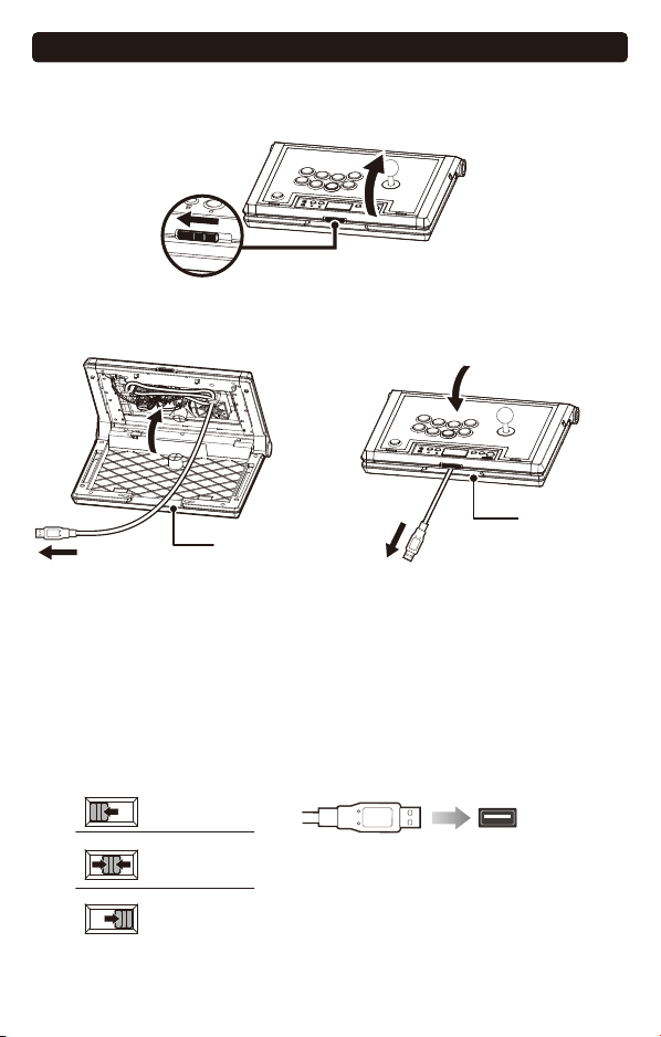
the product to resume normal operation by following the instruction manual (How to connect). In case the
function does not resume, please relocate to an area which does not have electro-magnetic interference to use
the product.
The wires are not to be inserted into socket-outlets.
The packaging must be retained since it contains important information.
US
Warranty
HORI warrants to the original purchaser that the product purchased new in its original packaging shall be free of any
defects in material and workmanship for a period of 1 year from the original date of purchase. If the warranty claim
cannot be processed through the original retailer please contact HORI customer support directly at info@horiu-
sa.com. Please visit http://stores.horiusa.com/policies/ for warranty details.
EU
Warranty
For all warranty claims made within the first 30 days after purchase, please check with the retailer where the original
purchase was made for details. If the warranty claim cannot be processed through the original retailer or for any
other inquiries pertaining to our products, please contact HORI customer support directly at [email protected].
“1”, “PlayStation”, “PS5”, “PS4”, “DualSense” and “DUALSHOCK” are registered trademarks or trademarks of
Sony Interactive Entertainment Inc.
All other trademarks are the property of their respective owners.
Manufactured and distributed under license from Sony Interactive Entertainment.
Simplified Declaration of Conformity
Hereby, HORI declares that this product is in compliance with Directive 2014/53/EU.
The full text of the EU declaration of conformity is available at the following internet address:
https://hori.co.uk/consumer-information/
For UK: Hereby, HORI declares that this product is in compliance with the relevant statutory requirements.
The full text of the declaration of conformity is available at the following internet address:
https://hori.co.uk/consumer-information/
Main Features
:410mm×300mm×120mm
:2.7kg
:3.0m
:HAYABUSA
:HAYABUSA
:HORIButton
ExternalDimensions
Weight
CableLength
Joystick
Button(△Button,○Button,×Button,□Button,
L1Button,L2Button,R1Button,R2Button)
Button( OptionButton)
Table of contents
Other HORI Video Gaming Accessories manuals

HORI
HORI HPC-042 User manual

HORI
HORI Ace Combat 7 User manual

HORI
HORI NSW-326 User manual

HORI
HORI Neckset User manual

HORI
HORI SPF-004 User manual

HORI
HORI Fighting Stick Mini User manual

HORI
HORI Racing Wheel Overdrive User manual

HORI
HORI NSW-373U User manual

HORI
HORI Split Pad Compact User manual

HORI
HORI RACING WHEEL PRO DELUXE User manual