Horizon Fitness PF-P3100 User manual

I
I Introduction
• This service manual is for the following product.
Paper Folder PF-P3100
• Prior consent
This service manual is intended for use when repairing and maintaining this
machine to keep it in top working condition. In order for you to safely perform
repair and maintenance work on this machine, please make sure that you fully
read and understand all of the notes related to safety that are written through-
out this service manual.
- Horizon International, INC. cannot accept responsibility for any loss, damage, or
injury as a result of unauthorized modification, misuse, or use outside the
machine’s specifications, or any unsuitable or inadequate maintenance performed
by you or by authorized service personnel.
- Horizon International, INC. is continuously working to improve the design and
performance of all of its products. Consequently, the contents of this service
manual may be changed at any time in the future without prior notice.
Furthermore, Horizon International, INC. bears no additional liability for any added
contents.
- All rights with regards to copyrights are reserved. The copying or distribution of
any part or whole of this manual is strictly prohibited unless prior written
permission is obtained directly from Horizon International, INC.
• Caution when undertaking service operations
- When replacing parts or performing other such maintenance operations, switch
the power supply Off before starting unless it is necessary to keep the power on.
Also, remove the power cable from the socket before starting for additional safety.
- When removing covers, be extremely cautious of rotating objects such as belts
and pulleys, and of electrical wiring etc.
- Always perform operations alone. This manual is written on the assumption that
operations will be performed by one person.
- Make sure that other people do not touch the machine during operation.
- When turning the power back on, wait for approximately 10 seconds after turning
the power Off before switching it On again.
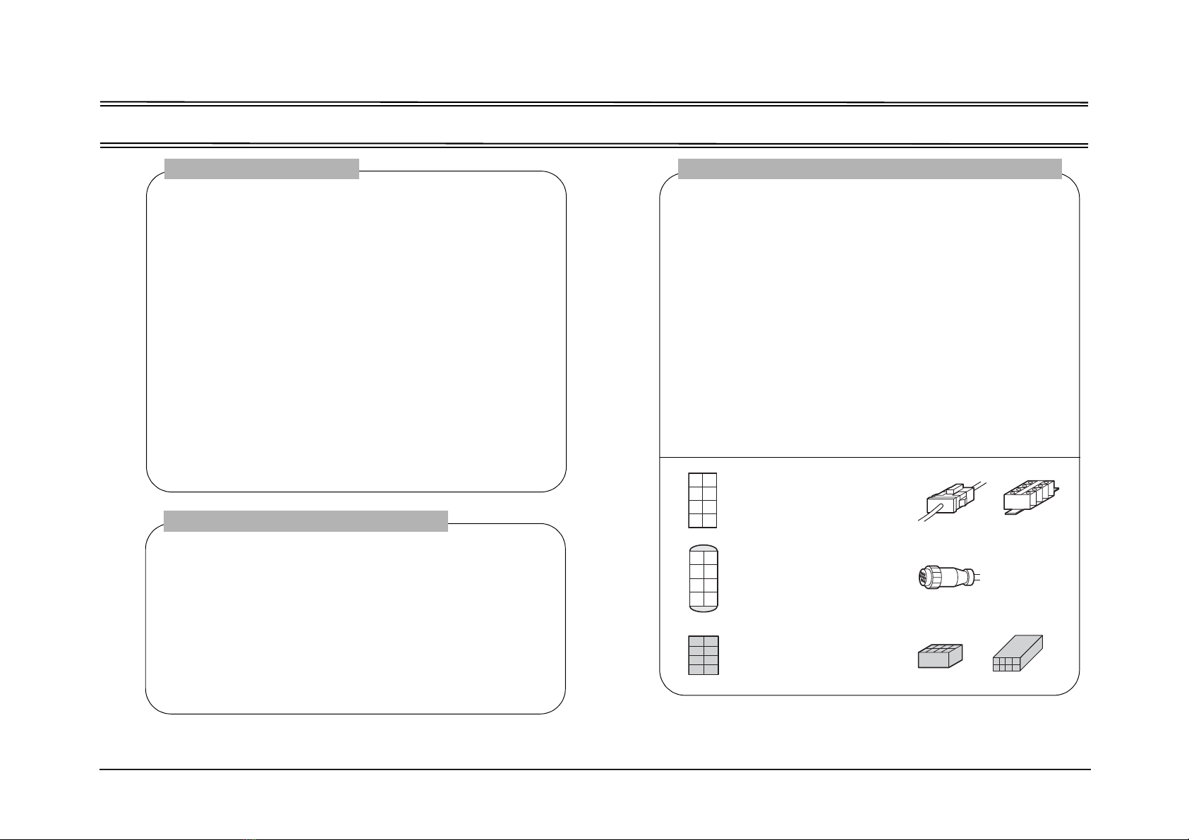
- When replacing parts, use the parts shown in the parts book unless commercially
available parts with exactly the same functions and performance can be obtained.
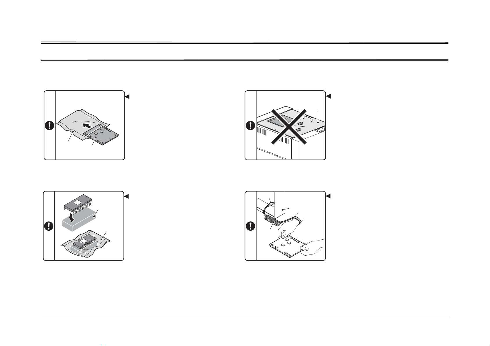
• Safety precautions
- In order to perform repair or maintenance work safely on this machine, thoroughly
read all of the warnings and cautions related to safety that are written in this
service manual BEFORE commencing any operation. Failing to heed the safety
precautions in this manual may lead to accidents resulting in injury or death.
- The maintenance procedures and safety precautions described in this service
manual are only effective if the repair/maintenance procedures specified for this
machine are followed.
- Precautions that if not followed correctly may lead to accidents resulting in injury
or death are indicated by this heading.
- Precautions that if not followed correctly may lead to accidents resulting in
machine damage or malfunctions are indicated by this heading.
- It is impossible for Horizon International, INC. to prevent all possible dangers
related to this product and its use. Therefore, the precautions shown in this service
manual and warning labels displayed on the product do not completely warn
against all possible dangers.
- Some of the diagrams in this service manual are drawn with covers removed to
describe the details or internal sections of the machine.
WARNING
CAUTION
Edited and Published by Horizon International, INC.
070608/PFP3100/00E/TM/HI,MT US503013-00

II
II Symbols used in this manual
Single color wire color Compound line symbol
BRN = Brown = Brown PW = Power system Cabtire
RED = Red = Red GY = Heater system Likal wire
ORN = Orange = Orange SD = Cap for stepping motor
YEL = Yellow = Yellow Tire
GRN = Green = Green IO = Cabtire for I/O signal
BLU = Blue = Blue IL = Interlock system Cabtire
VIO = Violet = Violet CC = Each unit junction cord
GRY = Grey = Grey
WHT = White = White
BLK = Black = Black
PIN = Pink = Pink
SKY = Sky = Sky blue
BRNNE = The [NE] that follows the color mark is the dark gray band that
is attached to one of the wires for identification purposes when there are
2 of the same color wires within the same bundle of wires.
RED/BLU = The /BLU that follows the color mark indicates that the
mother color of the wire is blue, and that on top there is a RED colored
stripe.
1. Wiring color character code
A** = Inverter/driver NF** = Noise filter
B** = Sensor PW** = Power cable No.
C** = Capacitor Q** = Circuit protector/
E** = Heater Breaker
F** = Fuse QPM** = (multi layer) board
G** = Power supply QPW** = (Single layer) board
H** = Indicating lamp S** = Switch
HS** = Temperature sensor T** = Transformer
K** = Connector X** = Terminal board
L** = Lamp Y** = Solenoid/clutch/
M** = Motor Valve etc.
2. Identification characters of electrical parts
AC = Alternating current MS = Micro-switch
BK = Brake MOD = Module connector
BL = Short circuit connector NF = Noise filter
CL = Clutch NC = Normal [closed] contact
terminal
CN = Connector NO = Normal [open] contact
terminal
COM = Common terminal SSR = Solid state relay
CON = Connector VR = Volume
CW = Clockwise direction SL = Solenoid
CCW = Counterclockwise SIG = Signal voltage
direction
DC = Direct current S/N = Machine number
DSW = Dip switch RAP = Trouble recovery procedure
F.G = Frame ground BSD = Electric block diagram
GND = Ground *X## = * Connector
JSW =Jumper switch
2
3
4
1
2
3
4
1
2
3
4
1
2
3
4
1
Junction connector, or
terminal board
Round connector
Short circuit connector
BL
3. Circuit configuration identification characters and symbols

III
III Cautions when handling the print board and ROM
Even an small amount of static electricity that it cannot be felt by people will damage the board or ROM.
Exercise caution on the following points when handling the board or ROM.
P.C.Board
Shield Bag
Keep Board in a
shield bag.
Put the ROM on a
conductive sponge
and keep in a shield
bag.
Shield Bag
Conductive
Sponge
Acrylic
Cover
Wrist
Strap
Clip
Machine
Frame
Do not put Board and ROM on the
machine, especially on the acrylic
cover. (No problem on the
conductive plate.)
And keep the Board and ROM away
from the insulators.
Insulators: Plastic, form polystyrene,
chemical fiber fabric,
dry paper, etc.
When replacing the Board and
ROM, or setting the dip switches
and volumes on the Board, wear a
wrist strap, and connect the clip to
the machine frame (not painted
surface).

IV
Table of Contents
I Introduction ........................................................................I
II Symbols used in this manual..........................................II
III Cautions when handling the print board and ROM.....III
1 Installation and Mechanism.............................. 1-1
1-1 Installation .......................................................................... 1-2
1-2 Main Cover Removal.......................................................... 1-3
1-3 Buckle Chute Removal....................................................... 1-4
1-4 Mechanism of Folding ........................................................ 1-5
1-5 Feed Table ......................................................................... 1-6
1-6 Table Up/Down Mechanism ............................................... 1-7
1-7 Drive Section...................................................................... 1-8
1-8 Feed Roller Section............................................................ 1-9
1-9 Double Feed Stop Section ............................................... 1-10
1-10 Fold Roller Section......................................................... 1-11
1-11 Tray Gate Section .......................................................... 1-12
1-12 Delivery Section ............................................................. 1-13
1-13 Buckle Chute Section..................................................... 1-14
2 Service Mode and Error Code.......................... 2-1
2-1 Functions of Service Mode................................................. 2-2
2-2 Error Code Chart................................................................ 2-3
3 Adjusting and Checking Procedures ................ 3-1
3-1 Buckle Chute Stopper Angle Adjustment ........................... 3-2
3-2 Feed Clutch Unit Adjustment ............................................. 3-3
3-3 Tray Gate Position Adjustment ...........................................3-4
3-4 Belt Tension Adjustment .....................................................3-5
3-5 Delivery Belt Replacement..................................................3-6
3-6 Micro-switch Adjustment .....................................................3-7
4 Mechanical Troubleshooting............................. 4-1
4-1 Machine Is Not Powered On ...............................................4-2
4-2 M10 Main Motor Does Not Rotate ......................................4-3
4-3 Tray Gate Malfunctions.......................................................4-4
4-4 Y01 Clutch Solenoid Does Not Activate..............................4-5
4-5 Buckle Chute Proximity Sensor Error .................................4-6
4-6 Delivery Belt Does Not Move ..............................................4-7
5 Folding Quality Troubleshooting....................... 5-1
5-1 Sheets Are Wrinkled ...........................................................5-2
5-2 Corner of the Sheets Are Folded (Dog Ear)........................5-3
5-3 Uneven Folding...................................................................5-4
5-4 Fold Skewing ......................................................................5-5
5-5 Delivered Sheets Are Not Neatly Stacked ..........................5-6
5-6 Sheet Jams at the Tray Gate ..............................................5-7
6 Electrical Circuit................................................ 6-1
6-1 Electrical Parts Location and Description ...........................6-2
6-2 Power Circuit Wiring Diagram and Interlock Circuit ............6-5
6-3 QPM-243 Control P.C.B......................................................6-6
6-4 QPW-767/QPW-768 Buckle Chute LED P.C.B...................6-8
6-5 Firmwae Update................................................................6-10

1-1
Installation and Mechanism
1
1 Installation and Mechanism
1-1............... Installation............................................................................ 1-2
1-2............... Main Cover Removal ........................................................... 1-3
1-3............... Buckle Chute Removal ........................................................ 1-4
1-4............... Mechanism of Folding.......................................................... 1-5
1-5............... Feed Table............................................................................ 1-6
1-6............... Table Up/Down Mechanism.................................................. 1-7
1-7............... Drive Section........................................................................ 1-8
1-8............... Feed Roller Section.............................................................. 1-9
1-9............... Double Feed Stop Section.................................................... 1-10
1-10............. Fold Roller Section............................................................... 1-11
1-11 ............. Tray Gate Section................................................................. 1-12
1-12............. Delivery Section.................................................................... 1-13
1-13............. Buckle Chute Section........................................................... 1-14

1 - 1 Installation
1 Installation and Mechanism
1-2
Open the package and take the folder
out of the box.
- Take all the accessories out of the box, too.
Place the folder on the table. (Fig.1)
Attach the support table. (Fig. 2)
Open the delivery tray. (Fig. 2)
Attach the delivery roller assembly.
(Fig. 3)
- Insert the rear end of the pin in the rear hole, and
push back in the direction shown by arrow 1. Pull
the front end of the pin into the front hole in the
direction shown by arrow 2.
Plug the power cable to the PF-P3100.
(Fig. 4)
Fig.1
Fig.2
Fig.3
Fig.4
1 - 1 Installation
- Do not install the PF-P3100 on an
unstable or tilted floor. Otherwise,
the folder may fall over or the
machine frame may be distorted,
and this could affect the machine
performance.
- The PF-P3100 weighs 37kg (81.4 lb.).
Install the PF-P3100 on the table
which can support this weight.
- This machine must be moved by at
least two people.
Caution
503013
1_1_1A
503013
1_1_1C
Delivery Tray
Support Table
503013
1_1_1B
Delivery Roller
Assembly
1
2
Pin
503013
1_1_1D
Power Cable

1 - 2 Main Cover Removal 1-3
Installation and Mechanism
1
1 Installation and Mechanism
1 - 2 Main Cover Removal
Remove the cover F.
- Remove three lock screws.
- Loosen two lock screws of the control
panel.
- Lift the control panel, and disengage the
control panel from the cover F.
- Remove the cover F.
Remove the cover R.
- Remove four lock screws.
- Remove the cover R.
When attaching the cover, it is easier to attach
the cover once the buckle chute unit is
removed.
503013
1_2_1A
Engage-
ment
Lock Screw for Control Panel
Control Panel
Cover F
Cover R
Control Panel
Cover F
B4-8Bx3
B4-8Bx4
B4-8B
B4-8B
B4-8B

1 - 3 Buckle Chute Removal
1 Installation and Mechanism
1-4
Pull out the buckle chute.
- Pull out the buckle chute to the arrow direction
slowly until it stops. (Fig. 1)
Remove the stopper bracket.
- Remove four lock screws of the stopper bracket
on the buckle chute at the bottom of the buckle
chute. (Fig. 2)
Remove the buckle chute.
- Pull out the buckle chute to the arrow direction to
remove. (Fig. 3)
- Remove the stopper bracket from the main body.
(Fig. 3)
Fig.1
Fig.2
Fig.3
Fig.4
1 - 3 Buckle Chute Removal
503013
1_3_1
A
Buckle
Chute
503013
1_3_1B
BuckleChute
Bottom Plane
Lock Screws
B4-6B
4
503013
1_3_1C
Frame F
Support Shaft 1
Support Shaft 2
Stopper Bracket
Frame R
503013
1_3_1D
Stopper
Bracket
BuckleChute
BuckleChute and Stopper Bracket
separated from the mainbody

1 - 4 Mechanism of Folding 1-51-5
Installation and Mechanism
1 Installation and Mechanism
1
Sheets are fed.
- The feed roller rotates and feeds sheet one by one
to the buckle chute. (Fig. 1)
The sheet hits the stopper.
- The sheet hits the stopper on the 1st buckle chute
and stops. (Fig. 2)
The sheet is bent slightly.
- The sheet stopped by the stopper is bent, and the
fold rollers catch the sheet bend. (Fig. 3)
- When the folding speed is set to “High”, the amount of
sheet bend is slightly changed. Set the stopper posi-
tion 1 mm (0.04”) shorter than the normal setting.
- When the heavier sheet is folded, the amount of sheet
bent becomes smaller. Set the folding speed to “High”
to create bigger sheet bend.
The sheet is folded.
- The fold rollers catch the bending part of sheet
and sheet is folded.
- The fold position changes depending on the stop-
per position.
Fig.1
Fig.2
Fig.3
Fig.4
1 - 4 Mechanism of Folding
503013
1_4_1A
Sheets
Feed Roller
DoubleFeed Stop Plate
503013
1_4_1C
1st BuckleChute
2nd BuckleChute
Stopper
503013
1_4_1B
Stopper
Bending Part
Feed Roller
FoldRoller
FoldRoller
503013
1_4_1D

1 Installation and Mechanism
1 - 5 Feed Table 1-6
1 - 5 Feed Table
503013
1_5_1
A
This rod is
eccentric.
Feed Angle Adjusting Mechanism
Slide Spring
Slide Spring
Slide Spring
Slide SpringSlide Spring
Guide Shaft
Sheet Detection
Switch
Feed Table Sheet
Actuator
Guide Shaft
Eccentric Rod
Lever Knob
Slide Block
Sheet Guide
Support Table
Feed Angle
Adjusting Mechanism
Feed Table Sheet
Actuator
S12 The lever knob plates hold
the guide shaft and this fix
the guide position.
The sheet guides can be
adjusted on this pivot.

1 - 6 Table Up/Down Mechanism 1-7
Installation and Mechanism
1
1 Installation and Mechanism
1 - 6 Table Up/Down Mechanism
503013
1_6_1A
S12
Feed Roller
Feed Table
Feed Table
Feed Tray Lever
Feed Tray
Lever
Feed Tray Lever
Feed Table
Pressure Adjusting Lever
Feed Table
Pressure Spring
Pressure Lever
Feed Table
Pressure Adjusting Lever
Feed Table
Pressure Spring
Pressure Lever
Feed Table
Feed Roller
(Strong)
(Strong)
(Strong)
(Normal)
(Normal)
(Normal)
Lever Cam Spring
Feed Tray Lever Cam
The tipof the feed tablelowers
when the feed tray lever pushes
thisshaft down.
Feet Table
Pushdown Shaft
Feed Table
Fulcrum Shaft
Section B
Section B
Section B
Section A
Section A
Section A
Section A
Section A
Section A
Section B
Section B
Section B
Set the lever to "Strong" to
increase the feed tablepressure.
Thisswitch detects
that the feed table
islowered.

1 Installation and Mechanism
1 - 7 Drive Section 1-8
1 - 7 Drive Section
503013
1_7_1A
Power Transport System
Feed Roller
FoldRoller
Delivery Section
Clutch Solenoid
Drive Timing Belt
Feed Drive Belt
Delivery Drive Belt
Delivery Belt
Conveyor Pulley
M10 MainMotor
M10 MainMotor
(DC brushless motor)

1 - 8 Feed Roller Section 1-9
Installation and Mechanism
1
1 Installation and Mechanism
1 - 8 Feed Roller Section
503013
1_8_1
A
Feed Roller
DoubleFeed Stop Plate
Sheet
Feed Table
Twist
Enlarged
Inner
Diameter
The feed roller rotates to the
arrow direction and feeds sheet.
The rotation of the clutch stopper
stops when the clutch lever lowers.
The clutch spring istwisted to
the arrow direction, and the inner
diameter of the clutch spring isenlarged.
Since the inner diameter of the
clutch spring isenlarged, the power
transmission to the feed roller shaft is
shut off, and the clutch bushing is
slipped on the clutch pulley.
The feed roller does not rotate although
the clutch pulley rotates.
Feed Roller
Feed Roller
Insert the feed roller shaft.
Free Bearing
Fixed Bearing
Fixed Bearing
Clutch Unit
Feed Table
DoubleFeed Stop Plate
Clutch Pulley
Clutch Pulley
Clutch Spring
Clutch Stopper
Clutch
Stopper
Clutch Solenoid
Clutch SolenoidClutch Solenoid
Inner diameter of the clutch spring
Inner
Diameter
Clutch Lever
Clutch Lever
Feed Roller Shaft
Clutch Bushing

1 Installation and Mechanism
1 - 9 Double Feed Stop Section 1-10
1 - 9 Double Feed Stop Section
503013
1_9_1A
Second sheet isstopped by the
friction of the doublefeed stop plate.
Feed Roller
Feed Roller
Feed Roller
Feed Roller
Feed Table
DoubleFeed Stop Plate DoubleFeed Stop Plate
DoubleFeed Stop Plate
DoubleFeed
Stop Plate
Sheet
Feed Table
Feed
Pressure
DoubleFeed
Stop Pressure
Plate Pressure Spring
Plate Stand Lever
Plate Bracket Lever
Plate Pressure Adjusting Plate
Plate Bracket
Plate Pressure
"Low"

1 - 10 Fold Roller Section 1-11
Installation and Mechanism
1
1 Installation and Mechanism
1 - 10 Fold Roller Section
503013
1_10_1A
3
2
4
3
5
2
4
1
3
5
2
4
1
3
5
4
2
Feed Roller
Feed Roller
Feed Roller
SolenoidO
SolenoidO
N =
N =
When the tray gate
When the tray gate
isat right.
isat right.
- When the solenoid
- When the solenoid
turns ON,the tray gate
comes close to the third
roller.
roller.
- The sheet that comes
through the second and
third
third
roller goes over
roller goes over
the tray gate and is
delivered.
delivered.
SolenoidOFF =
SolenoidOFF =
When the tray gate isat left.
-
When the solenoid
When the solenoid
turns OFF,the tray gate
moves to the left and
makes aspace between
the tray gate and the
third roller.
third roller.
- The sheet that comes
through the second and
third roller deflects at
the tray gate, then goes
to the second buckle
chute through the third
and fourth roller.
and fourth roller.
Transport Rubber Roller
Upper Guide Plate
HoldSpring
RGate
FoldRoller 2
FoldRoller 4
Tray Gate FoldRoller 1
FoldRoller 3
FoldRoller 5
1st BuckleChute
2nd BuckleChute
Feed Table
Sheet
Roller Pressure Link
FoldRoller Spring
Press the folddriven rollers.
Tray Gate
1st Buckle
2nd Buckle

1 Installation and Mechanism
1 - 11 Tray Gate Section 1-12
1 - 11 Tray Gate Section
503013
1_11_1
A
Gate Bracket
Adjust the tiltof the tray gate and the
internal contact with the 14 holeby adjusting
the tray gate bracket using these two holes.
Tray Gate Section
Tray Gate
Tray Gate
Gate Bracket
Gate Solenoid
(front)
Gate Solenoid(front)
Gate Fulcrum Shaft
Gate Fulcrum Shaft
Gate Lever (front)
Gate Lever (front)
Side Plate
When SolenoidON:
When SolenoidON:
When SolenoidOFF:
When SolenoidOFF:
The stop position of the tray
gate iswhere the gate hits
inside the 14 holeon the
side plate.
Lock the tray gate with thisscrew.
Tray Gate Bracket
14 holeon the side plate

1 - 12 Delivery Section 1-13
Installation and Mechanism
1
1 Installation and Mechanism
1 - 12 Delivery Section
503013
1_12_1
A
M10
M10
M10
M10M10M10M10M10M10
M10M10M10
M10
M10
M10
MainMotor
Conveyor Pulley
Conveyor Pulley
Delivery Belt
Delivery Belts
Delivery Tray
Adjust the belttension
by fixing position of the
shaft.
Tension Adjustment
Tension Adjustment
of the Delivery Belt
M10M10
MainMotor

1 Installation and Mechanism
1 - 13 Buckle Chute Section 1-14
1 - 13 Buckle Chute Section
503013
1_13_1A
57 mm (2.2")
57 mm (2.2")
Timing Belt
Timing Belt
Timing Belt
1st Stopper
1st Stopper
1st Stopper
Stopper
Stopper
Stopper
2nd Buckle
2nd Buckle
2nd Buckle
LED
LEDLED
LED
Buckle Chute
Section
Stopper Pointer
Stopper Pointer
1st Buckle
1st Buckle
1st Buckle
Home Position of Buckle Chute
Stopper
Move Shaft
Timing Pulley
Timing Pulley
Handwheel
Handwheel
Stopper
Move Shaft
Proximity Sensor:
B
21
21
1st Buckle
1st Buckle
Chute Stopper
Chute Stopper
2nd Buckle Chute Stopper
Loosen the lock screws,
and then adjust the position
of the stopper pointer.
Stopper Unit
Stopper Unit
Proximity Sensor for 1st Buckle Chute :
B
21
21
Proximity Sensor for 2nd Buckle Chute :
B
22
22
Slide
Sensor Bracket
Sensor
Spring
Proximity Sensor Unit
Set the first and second stopper at 57 mm (2.2") from the
entrance of the buckle chute. Align the stopper pointer to the left-
most LED on the buckle chute.
Home Position of Buckle Chute Stopper
2nd Buckle
2nd Buckle
When the stopper moves
forward to the gate of the
buckle chute, the whole
sensor bracket slide to the
arrow direction.
Section A
Section A
Section A
Section A
Section A
Section A
Lock Screws
Lock Screws
Lock Screws
Lock
Lock
Screws
Screws
Lock
Screws
Lock
Screws
Stopper
Stopper
Stopper 2nd
Stopper

Service Mode and Error Code
22-1
2 Service Mode and Error Code
2-1............... Functions of Service Mode .................................................. 2-2
2-2............... Error Code Chart.................................................................. 2-3

2 Service Mode and Error Code
2 - 1 Functions of Service Mode 2-2
2 - 1 Functions of Service Mode
The service mode is the functions listed in the chart to
the right can be performed by pressing the power
switch and the other buttons together.
To exit the service mode, turn off the power switch.
503013
2_1_1A
Power Switch : ON
Sheet Size Select Button
Clear Button
Display
Start/Stop Button
Test Button
Service Mode How to Enter What You Can Do in This Mode
Memory writing
error reset mode
Turn on the power switch while pressing
the Start/Stop, Test and Clear buttons on
the control panel simultaneously, and hold
down the buttons for 5 seconds until
buzzer sounds.
When “E7” (memory error) occurs, and the
machine is not recovered by turning the power
off and on, the memory can be reset in this
mode. (This memory will be returned to the
default value.)
Life counter check
mode
Turn on the power switch while pressing
the Start/Stop button on the control panel,
and hold down the button for 5 seconds
until buzzer sounds.
Life counter can be displayed. The last two
digits are not indicated.(For example “10” is
indicated when 1,000 sheets were folded.)
The life counter is cleared to “0” by pressing
the Clear button for 5 seconds.
Software version
check mode
Turn on the power switch while pressing
the Start/Stop, Test and Sheet Size Select
buttons on the control panel simulta-
neously, and hold down the buttons for 5
seconds until buzzer sounds.
Current software version is displayed, for
example “v0.77”.
Error-ignoring
check mode
Turn on the power switch while pressing
the Start/Stop and Test buttons on the con-
trol panel simultaneously, and hold down
the buttons for 5 seconds until buzzer
sounds.
In this mode, error is not detected at all. Oper-
ation can be performed as usual. (“8888” is
displayed when the Clear button is pressed.)
S13: Feed Table
Sheet Detection
switch ignoring
mode
1. Enter into the error-ignoring check
mode.
2. Press the Clear button for 5 seconds
until buzzer sounds.
In this mode, the folder can be used even if
S13 Feed Table Sheet Detection switch is bro-
ken down.
S12: Feed Bar
switch ignoring
mode
1. Enter into the error-ignoring check
mode.
2. Press the Start/Stop button for 5 sec-
onds until buzzer sounds.
In this mode, operator can use the folder even
if S12 Feed Bar switch is broken down.
Other manuals for PF-P3100
1
Table of contents
Other Horizon Fitness Folding Machine manuals

Horizon Fitness
Horizon Fitness H-1000XP User manual

Horizon Fitness
Horizon Fitness SPF-10 User manual

Horizon Fitness
Horizon Fitness PF-P280 User manual

Horizon Fitness
Horizon Fitness PF-P320 User manual

Horizon Fitness
Horizon Fitness PF-P330 User manual

Horizon Fitness
Horizon Fitness SPF-10 User manual

Horizon Fitness
Horizon Fitness SPF-10II User manual

Horizon Fitness
Horizon Fitness CRF-362 User manual

Horizon Fitness
Horizon Fitness AFC-566F User manual

Horizon Fitness
Horizon Fitness SPF-20A User manual