Horizon Fitness PC-P430 User manual

1
●Safety Precautions
-In order to perform repair or maintenance work safely on this machine, thoroughly
read all of the warnings and cautions related to safety that are written in this
service manual BEFORE commencing any operation. Failing to heed the safety
precautions in this manual may lead to accidents resulting in injury or death.
-The maintenance procedures and safety precautions described in this service
manual are only effective if the repair/maintenance procedures specied for this
machine are followed.
-Precautions that if not followed correctly may lead to accidents resulting in injury
or death are indicated by this WARNING heading.
-Precautions that if not followed correctly may lead to accidents resulting in
machine damage or malfunctions are indicated by this CAUTION heading.
-It is impossible for Horizon International, INC. to prevent all possible dangers
related to this product and its use. Therefore, the precautions shown in this
service manual and warning labels displayed on the product do not completely
warn against all possible dangers.
-Some of the diagrams in this service manual are drawn with covers removed to
describe the details or internal sections of the machine.
●The meanings of symbols are following.
Important
This will help you to avoid an incorrect operation which may cause
problems with the machine, or make it necessary to go back to a
previous step.
Note This indicates a helpful hint.
Additional
Information
This indicates additional information which will help you to operate
the machine efciently.
Attention This explains functional limitations and restrictions on the
operation of the machine.
Edited and Published by Horizon International, Inc.
140927/PC-P430/00E/HN/KJ US504013-00(001)
I
Introduction
●This service manual is for the following product.
Paper Cutter PC-P430
●Prior consent
This service manual is intended for use when repairing and maintaining this
machine to keep it in top working condition. In order for you to safely perform
repair and maintenance work on this machine, please make sure that you fully
read and understand all of the notes related to safety that are written throughout
this service manual.
-Horizon International, INC. cannot accept responsibility for any loss, damage,
or injury as a result of unauthorized modication, misuse, or use outside
the machine’s specications, or any unsuitable or inadequate maintenance
performed by you or by authorized service personnel.
-Horizon International, INC. is continuously working to improve the design
and performance of all of its products. Consequently, the contents of this
service manual may be changed at any time in the future without prior notice.
Furthermore, Horizon International, INC. bears no additional liability for any
added contents.
-All rights with regards to copyrights are reserved. The copying or distribution
of any part or whole of this manual is strictly prohibited unless prior written
permission is obtained directly from Horizon International, INC.
●Directions are described as followings in this manual.
*US504013*
When you print this manual, use the newest Adobe Reader.
Left
Right
Front
Rear

2
II
Symbols used in this manual
Circuit conguration identication characters and symbols
1. Wiring color character code
BRN *=The (*) that follows the color mark is the dark gray band that is
attached to one of the wires for identication purposes when there are 2 of
the same color wires within the same bundle of wires.
RED/BLU = The /BLU that follows the color mark indicates that the mother
color of the wire is blue, and that on top there is a red colored stripe. *
* The following wiring color character
codes have been modied. The
new codes are used from January
2013.
-BLU/GRY (Grey)
→ BLU/LBLU (Light blue)
-BLU/VIO (Violet)
→ BLU/PNK (Pink)
2
3
4
1
2
3
4
1
2
3
4
1
2
3
4
1
Junction connector, or terminal board
Short circuit connector BL
2. Identication characters of electrical parts
Single color character code
BRN = Brown = Brown
RED = Red = Red
GRY = Grey = Grey
YEL = Yellow = Yellow
GRN = Green = Green
BLU = Blue = Blue
VIO = Violet = Violet
WHT = White = White
BLK = Black = Black
ORN = Orange = Orange
PNK = Pink = Pink
LBLU = Light blue = Light blue
MOD =Module connector
NC =
Normal [closed] contact terminal
NO =
Normal [open] contact terminal
SSR =Solid state relay
VR =Volume
SIG =Signal voltage
S/N =Machine number
BSD =Block schematic diagram
*X## =* Connector
AC =Alternating current
BL =Short circuit connector
COM =Common terminal
CON =Connector
CW =Clockwise direction
CCW =
Counterclockwise direction
DC =Direct current
DSW =Dip switch
F.G =Frame ground
GND =Ground
JSW =Jumper switch
Round connector (CPC)
PG** =Encoder
Q** = Circuit protector
/Breaker
QPM** =(Multi layer) board
QPW** =(Single layer) board
RY** =Relay (on the board)
S** =Switch
T** =Transformer
X** =Terminal board/connector
Y** =Solenoid/clutch/Valve etc.
Z** =Noise Filter
A** =Inverter/driver/amplier
B** =Sensor
C** =Capacitor
E** =Heater
F** =Fuse
G** =Power supply
H** = Indicating lamp
/illumination
K** =Contactor/relay/SSR
L** =Reactor
M** =Motor

3
Shield Bag
Plastic Cover
Shield Bag
Conductive
Sponge
Machine
Frame
Clip
Wrist
Strap
P.C.Board
WARNING
WARNING
WARNING
CAUTION
CAUTION
CAUTION
Lock the keys when you
turned off the Power switch.
When replacing parts or performing other such main-
tenance operations, turn the power off unless it is
necessary to keep the power on. Also, lock the Power
switch before doing service operations.
-
This prevents another person from turning on the Power
switch without knowing that you are doing service opera-
tions.
-
There are three holes for keys. If more than one person
does service operations at the same time, each person
should lock the Power switch separately.
Beware of rotat-
ing objects.
Do operations
alone.
Wait ten second
before turning on
the power again.
Use the correct
parts.
Prepare a special
wrench when you
replace the safety
switches
If you need to do service operations while operat-
ing the machine, be extremely cautious of rotating
objects such as belts and pulleys etc. Otherwise,
it may cause the severe personal injury.
Always do operations alone when operating
the machine. This manual is written on the
assumption that operations will be done by
one person.
When turning the power back on, wait for
approximately ten seconds after turning the
power off before turning it on again.
When replacing parts, use the parts shown
in the parts book unless commercially avail-
able parts with exactly the same functions
and performance can be obtained.
Special screws are used to mount the safe-
ty switches, which detects that the cover is
opened or closed. This prevents the users
from removing the safety switches.
Beware
of static
electricity
Even an small amount of static electricity that it can-
not be felt by people will damage the board or ROM.
Exercise caution on the following points when han-
dling the board or ROM.
Keep Board in a
shield bag.
Do not put Board and ROM on the machine, especially on
the plastic cover. (No problem on the conductive plate.)
And keep the Board and ROM away from the insulators.
Insulators: Plastic, form polystyrene,
chemical ber fabric, dry paper, etc.
Put the ROM on a
conductive sponge
and keep in a shield
bag.
When replacing the Board and ROM, or setting the DIP
switches and volumes on the Board, wear a wrist strap,
and connect the clip to the machine frame (not painted
surface).
●The description in this page is common issue in the Horizon products.
The description unrelated to this machine may be contained.
CAUTION
III
Cautions when undertaking service operations - Part 1

4
CPU
CPU
CAUTION
CAUTION
Handling the on-board lithium battery
Manipulation de la batterie au lithium intégrée
Handling the digital counter
Manipulation du compteur numérique
If the battery is replaced with the wrong one, it way cause an explosion.
The battery should be kept in a place where the temperature does not rise
above 60 degrees Celsius (140 degrees Fahrenheit).
Do not throw away the used battery as household waste.
Dispose of or recycle the battery according to the regulations and/or ordinanc-
es of your local government.
Un remplacement de la batterie par une mauvaise batterie peut entraîner une
explosion.
La batterie doit être conservée dans un endroit où la température ne dépasse
pas 60 degrés Celsius (140 degrés Fahrenheit).
Ne pas jeter la batterie usagée avec les déchets ménagers.
Jeter ou recycler la batterie conformément à la réglementation et/ou
aux décrets des autorités locales.
A battery is mounted inside the digital counter.
Dispose of or recycle the battery according to the regulations and/or
ordinances of your local government.
Une batterie se trouve à l’intérieur du compteur numérique.
Jeter ou recycler la batterie conformément à la réglementation et/ou
aux décrets des autorités locales.
●The description in this page is common issue in the Horizon products.
The description unrelated to this machine may be contained.
Lithium
battery
Batterie au
lithium
IV
Cautions when undertaking service operations - Part 2

5
Contents
I Introduction ....................................................................................................... 1
II Symbols used in this manual ........................................................................... 2
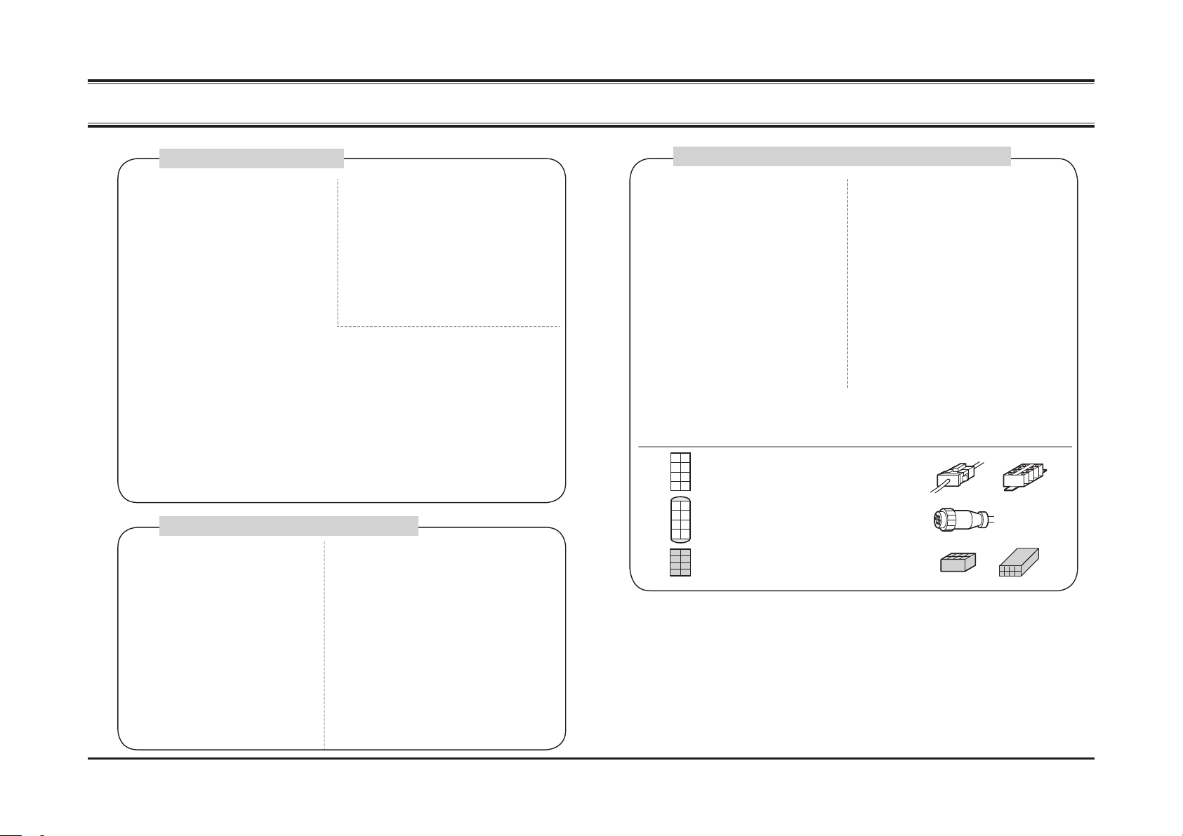
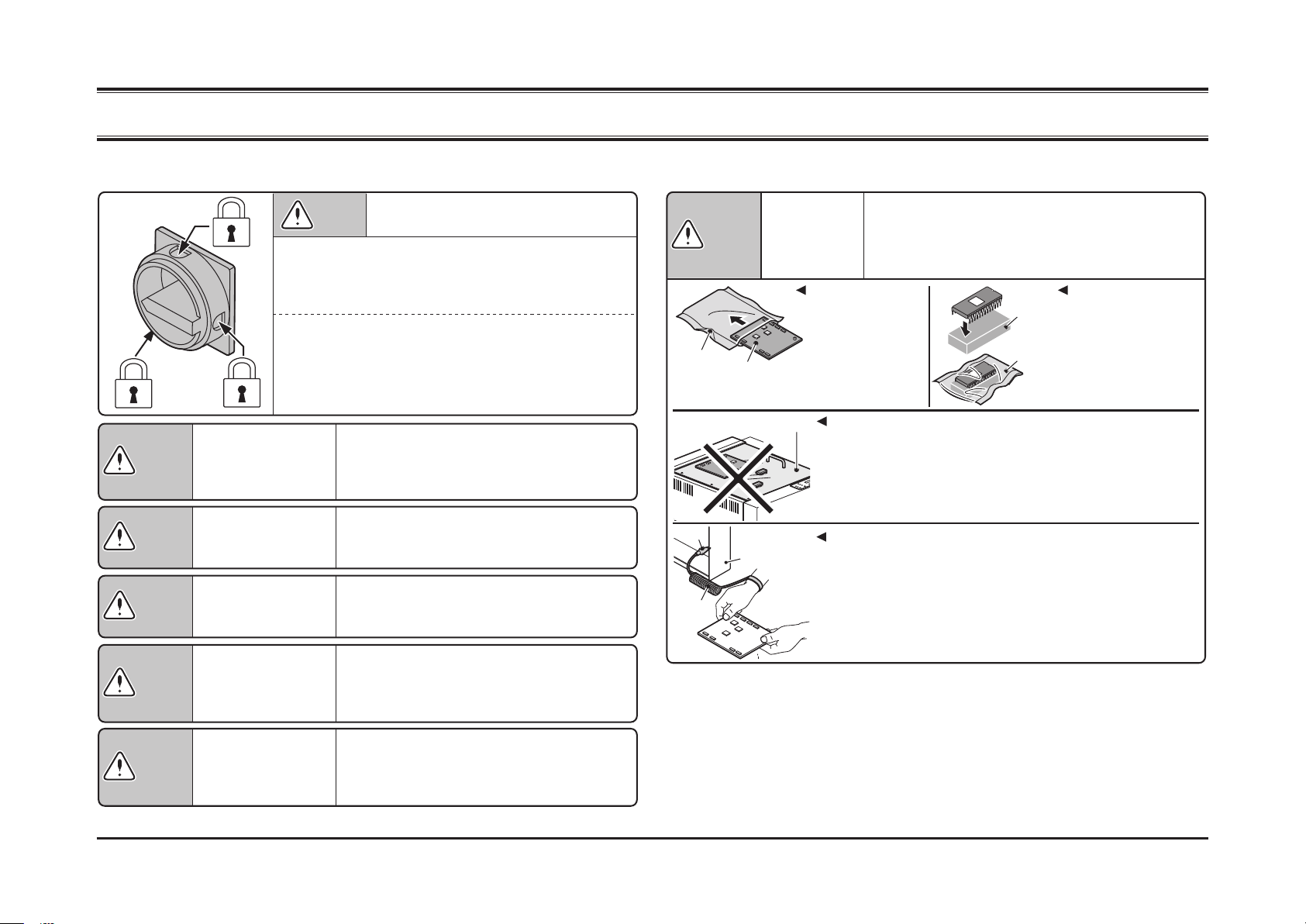
III Cautions when undertaking service operations - Part 1 ................................. 3
IV Cautions when undertaking service operations - Part 2 ................................. 4
1 General .............................................................................. 7
1 - 1 Differences from the PC-P43 .................................................................... 8
1 - 2 Adjusting the Angle and the Height of the Knife ........................................ 9
1 - 3 Machine Safety Features ........................................................................ 11
2 Troubleshooting ............................................................... 15
2 - 1 System Errors ......................................................................................... 16
2 - 2 Monitor LEDs Do Not Light ..................................................................... 19
2 - 3 The Machine Does Not Start by Pressing the Cutting Buttons ............... 20
2 - 4 The Machine Stops (System error 8 or 9) ............................................... 21
2 - 5 The Machine Stops Without a Beeping Sound ....................................... 22
2 - 6 The Last Few Sheets Are Left Uncut ...................................................... 23
2 - 7 Cut Size Is Not Accurate ......................................................................... 24
2 - 8 Skew Cut ................................................................................................. 25
2 - 9 The Book Spine Is Crashed / The Book Is Contaminated ....................... 26
2 - 10 Vague Cut Line ..................................................................................... 27
3 Descriptions of Mechanisms............................................ 31
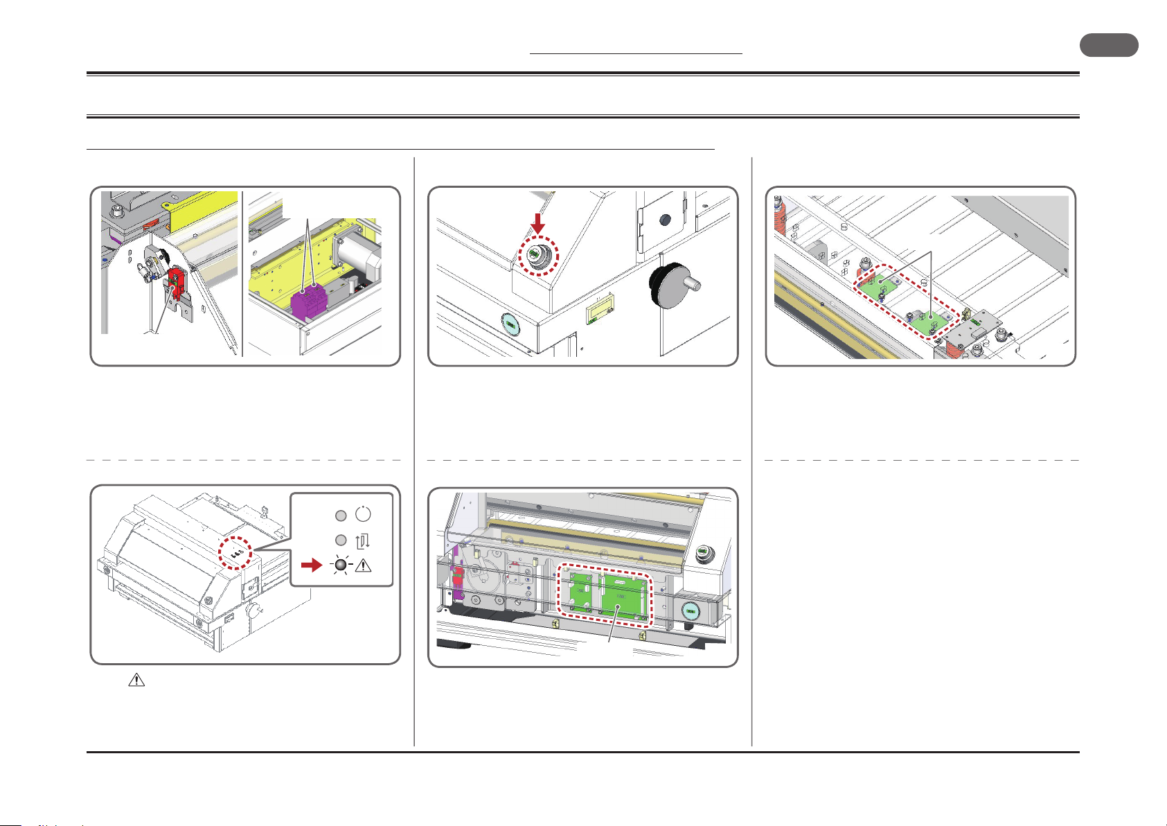
3 - 1 Cutting and Clamp Section ..................................................................... 32
3 - 2 Backgauge Section ................................................................................. 33
3 - 3 Safety Cover Section .............................................................................. 34
3 - 4 Removing the Back Table ...........................................................................35
3 - 5 Removing the Front Table ...........................................................................36
3 - 6 Removing the Clamp ...................................................................................38
3 - 7 Removing the Knife Holder .........................................................................39
3 - 8 Removing the Cam .....................................................................................40
3 - 9 Removing the Backgauge Drive Section .....................................................41
3 - 10 Removing the Motor ..................................................................................42
3 - 11 Replacing the Knife ...................................................................................43
4 Electrical Parts Location .....................................................51
4 - 1 PC-P430 Electrical Parts List ......................................................................52
4 - 2 Motor and Switch Locations and Names .....................................................54
4 - 3 Other Electrical Parts Locations and Names ..............................................55
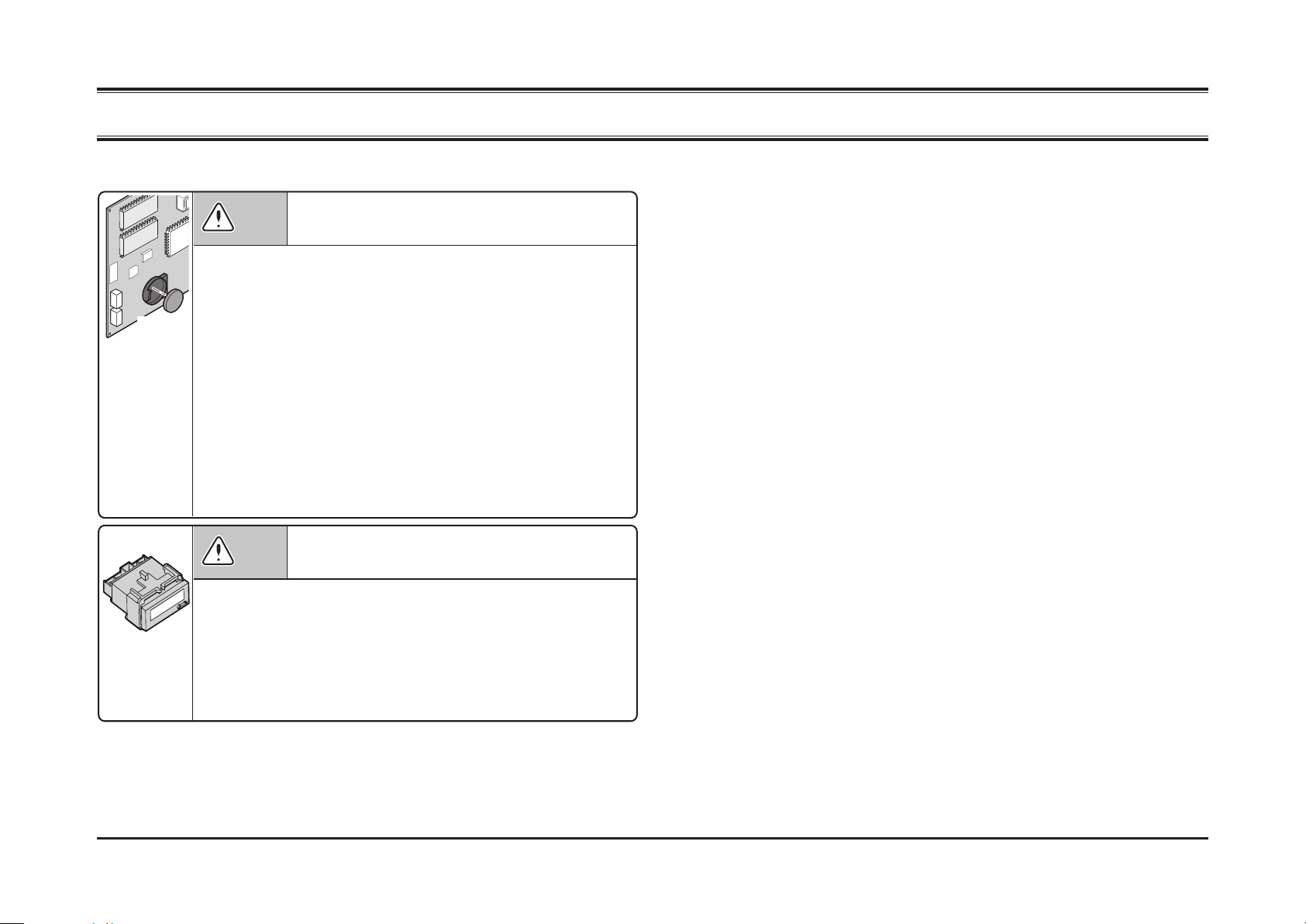
5 Circuit Boards .....................................................................59
5 - 1 Board Locations and Names .......................................................................60
5 - 2 QPW-968 (P115811) Control Board ...........................................................61
5 - 2 - 1 QPW-968 Board Diagram ...................................................................................... 61
5 - 2 - 2 QPW-968 LED Location ......................................................................................... 62
5 - 3 QPW-959 (P114711) Cut Line LED Current Control Board ........................63
5 - 4 QPW-969 (P115911) LED Board ................................................................64
5 - 11 ROM Version History ................................................................................65
6 Electrical Circuits ................................................................69
6 - 1 SD Circuit ....................................................................................................70
6 - 1 - 1 SD1 AC Power Circuit ............................................................................................ 70
6 - 1 - 2 SD2 Input and Output System Circuit .................................................................... 71
END SHEET ...............................................................................................74

This page is intentionally left blank.

General
1
PC-P430
7
1 General
PC-P430

1 General
Differences from the PC-P43
PC-P430
8
1 - 1
Differences from the PC-P43
1 - 1 - 1
What Is Improved
■The bulb is changed to the white LED.
404018
1_1_1E
•For the high brightness LED, new two QPW-960 Cut Line
LED Boards and the QPW-959 Cut Line LED Current Control
Board are added.
■
The Power switch is omitted and there is the Key switch only.
404018
1_1_1C
■Safety devices are enhanced.
404018
1_1_1A
•In addition to the original mechanical lock guard, two inter-
lock contactors K01 and K02 are added to have a redundant
circuit.
The fault self-checking function is also equipped. (See below
for details.)
■
The Knife Lower Limit switch is mounted on the P.C.board.
404018
1_1_1D
•The knife is set by the Toggle switch on the QPW-968 control
board to stop at the lower limit. (See page 61 for details.)
■The fault self-checking device is equipped.
404018
1_1_1B
•The lamp shows where a fault is according to the fre-
quency of ashes.
(See page 16 for details.)
S10 Cover switch is
added also at left side.
K01/K02 contactors
are added.
QPW-968
QPW-960

General
1Adjusting the Angle and the Height of the Knife
PC-P430
9
1 - 2
Adjusting the Angle and the Height of the Knife
1 - 2 - 1
Adjusting the Angle and the Height of the Knife
1Place the sheets. (Fig.1)
•Cut the sheets of 64 gsm (the common copy paper) into
strips, and place four sheets on the left end and one
sheet on the right end.
•The numbers of sheets differ between the right side and
left side because the left side of the knife cuts into the
sheets more deeply than right side (the left side of the
knife holder is pulled) when the machine cuts the sheets
actually. Therefore, the stack on the left side must be
higher by three sheets.
2Set the Toggle switch on the QPW-968 to
"ADJ". (Fig.2)
→The three LEDs at the monitor light up in order. The LED
L1 on the QPW-968 control board is lit.
(See Fig.7 on the next page.)
3Press the Right and Left Cutting buttons.
•The knife will lower and stop at the lower limit.
4Turn off the Key switch.
5Adjust the height. (Fig.3)
•Loosen the lock nut, and adjust the height by turning the
adjusting screw so that the knife edge touches the top
sheet of the four sheets on the left side.
6Adjust the angle. (Fig.4)
•Loosen the locking screw, and adjust the angle by turn-
ing the eccentric pin so that the knife edge touches the
sheet on the right.
(Continued to the next page.)
Fig.2 Toggle Switch on the Board
Fig.1 Placing the Sheets
Fig.4 Adjusting the angle
Fig.3 Adjusting the height
404018
1_2_1A
404018
1_2_1C
ADJ
NORMAL
404018
1_2_1B
404018
1_2_1D
4 sheets on the left 1 sheet on the right
Do not turn the adjusting screw more than ± 45 de-
grees from the factory setting position.
When you turn the eccentric pin using
the straight slot screwdriver, only the
right side of the knife moves down and
up.
Monitor
LEDs light up in order.
QPW-968 Control
Board Toggle Switch
Loosen
Lower
Loosen
Right-hand Screw
Lock Nut
Adjusting
Screw
Left-hand Screw
Lock Nut
Locking Screw
Eccentric Pin

1 General
Machine Safety Features
PC-P430
10
(Continued)
7Check the points shown in Fig.5 and return
the toggle switch on the board to "NOR-
MAL". (Fig.2)
8Press the Right and the Left Cutting but-
tons.
Turn on the Key switch, and press the Right and the Left
Cutting buttons together. The knife will move up and stop at
the upper limit.
9Turn off the Key switch.
10 Lower the knife. (Fig.6)
•Loosen the lock nut and turn the adjusting screw by 30
degrees as shown in the drawing, and then tighten the
lock nut. After you make this adjustment, the knife cuts
into the cutting stick by 0.5 mm (0.02").
The lower knife height results in the deeper cut into the
cutting stick. It is effective to solve the problem that the
sheet remains uncut on either side. If the knife height is
too low, the cutting stick needs to be replaced earlier.
Adjust the knife height so that the knife cuts into the
cutting stick by 0.5 mm (0.02").
11 Cut the sheets as a test.
•Cut the sheets (width: more than 400 mm [15.8”], stack
height: higher than 20 mm [0.9”]) and check that the no
sheets are left uncut.
■As you operate the machine to adjust the angle and
the height of the knife, the LEDs on the QPW-968
control board are lit as shown in the table of Fig.7.
Fig.6 Lowering the knife
Fig.5 Point to be checked
Fig.7 LEDs Lighting Condition
404018
1_2_1E
■LEDs on the QPW-968 control board
on, off
Lighting Condition L2 L1 L3 L6
When the Toggle switch on the board
is set to "ADJ"
When S05 Left Cutting button and
S06 Right Cutting button are pressed
at the same time
When the knife starts lowering
When the knife reaches the lower
limit
When S05 Left Cutting button
and S06 Right Cutting button are
released
When the Toggle switch on the board
is set to "NORMAL"
When S05 Left Cutting button and
S06 Right Cutting button are pressed
When the knife starts lifting
When the knife reaches the upper
limit
When S05 Left Cutting button
and S06 Right Cutting button are
released
L2:
S05 Left Cutting button and S06 Right Cutting button pressed at the same time
L1: Toggle switch
L3: S04 Cam Switch A
L6: S03 Cam Switch B
404018
1_2_1F
The lock nuts are not
loosened.
Loosen
Lower
Loosen
Right-hand Screw
Lock Nut
Adjusting Screw
Turn the screw counter-
clockwise by 30 degrees to
lower the knife.
The knife cuts into the
cutting stick by 0.5 mm
(0.02").
Left-hand Screw
Lock Nut
Right-hand
Screw Lock Nut
Left-hand
Screw Lock Nut
The locking screw
is not loosened.
The eccentric pin is not
projecting.

General
1Machine Safety Features
PC-P430
11
404018
1_3_1A
1 - 3
Machine Safety Features
1 - 3 - 1
Machine Safety Features
Safety Precautions
1. The machine has many safety features as shown in this
page. However, do not forget that the machine needs these
features because the machine has hazardous function and
parts.
2. If one of these features are removed or converted, it consid-
erably increases risk for personal injury.
3. The machine will be broken eventually. Though this machine
is a table top machine, the users must not try to x the
machine. It can cause sever personal injury.
Service technicians should understand these safety precau-
tions 1. through 3., and instruct the users.
404018
1_3_1
C
K10
K11
404018
1_3_1
E
404018
1_3_1B
404018
1_3_1
D
The machine is protected by
the covers which prevent op-
erator's hands from reaching
any dangerous parts during
operation. Fingertips and
clothes will not be caught by
the dangerous parts.
When the door for replacing
the knife is open, the safety
interlock function works and
the cutting operation can not
be started.
If one (or both) of the Cutting
buttons is released while the
machine is cutting, the knife
will move up (move in the
safer direction).
The machine is equipped with
a lever which moves the cut
sheets forward. The opera-
tor can remove the cut sheets
safely by pulling the lever to
the operator side. The operator
does not need to put the hands
under the
knife.
The machine cuts the sheets
only when both Cutting buttons
are pressed within 0.5 seconds.
While the machine is cutting, the
operator is using the two hands
to press the both Cutting buttons.
Therefore, operator's hands can-
not be under the knife.
The authorised operator
should be assigned to super-
vise use of the machine.
Only that person should
have access to the key of the
switch.
If the safety cover is open,
the knife is locked both elec-
trically and mechanically.
The knife can be replaced
without touching it directly. Keep
the removed knife in the sheath.
Even if the knife is dull, the knife
can cause severe personal in-
jury. Service technicians should
retrieve the removed knife.
The machine has the motor con-
tactors for normal cycle and the
reverse cycle. When one of the
contactor is turned on, the other
contactor cannot be turned on. If
the switches to detect the knife
position are broken, the machine
stops immediately.
While the machine is cutting,
the safety cover is locked
mechanically. Therefore,
other people cannot open
the cover and put their hands
in the machine, while the ma-
chine is cutting.
(Cutting) (Cutting) (Cutting)
Lock!
Lock!
Lock!

1 General PC-P430
12
This page is intentionally left blank.

General
1
PC-P430
13
This page is intentionally left blank.

1 General PC-P430
14
This page is intentionally left blank.

Troubleshooting
2
PC-P430
15
2 Troubleshooting
PC-P430

2 Troubleshooting
System Errors
PC-P430
16
2 - 1
System Errors
Error Lamp
Description and Causes Solutions
1
Deposition of
K10 Contactor for Normal Rotation
Turn off the power and check that the contact points on K10 are not damaged.
If the contact points are not damaged, check the wiring/connection between terminals 13 and 14 on K10 and CON2 on the QPW-968
control board. If these are OK, the board is defective. Replace it.
Function Error of
K10 Contactor for Normal Rotation
Check whether the L5 on the QPW-968 control board is lit while the knife is running in normal direction.
If the LED is lit, go to 1. If not, go to 2.
1. The LED is lit.
The correct signals are input from K10 to the board, but the signals
are not being processed correctly. Replace the board.
2. The LED is not lit.
Check the wiring/connection between terminals 13 and 14 of K10 and
CON2 on the QPW-968 control board. If this is OK, replace K10.
2
Deposition of
K11 Contactor for Reverse Rotation
Turn off the power and check that the contact points on K11 are not damaged.
If the contact points are not damaged, check the wiring/connection between terminals 13 and 14 on K11 and CON2 on the QPW-968
control board. If these are OK, the board is defective. Replace it.
Function Error of
K11 Contactor for Reverse Rotation
Check whether the L4 on the QPW-968 control board is lit while the knife is running in reverse direction.
If the LED is lit, go to 1. If not, go to 2.
1. The LED is lit.
The correct signals are input from K11 to the board, but the signals
are not being processed correctly. Replace the board.
2. The LED is not lit.
Check the wiring/connection between terminals 13 and 14 on K11 and
CON2 on the QPW-968 control board. If this is OK, replace K11
.
404018
2_1_1A
If there is a problem with the electrical parts, the lamp ashes to indicate the part that has a
problem.
• The lamp ashes by the error number in 0.4 second cycles, and turns off for
one second. The lamp repeats ashing and being off.
• Example of ashing (In case of the error 2)
On for 0.2 seconds → Off for 0.2 seconds → On for 0.2 seconds → Off for one second.
•The machine is able to run after a buzzer sounds and the power is turned off
and then turned on again.

Troubleshooting
2System Errors
PC-P430
17
Error Lamp
Description and Causes Solutions
3
Deposition of K01 Interlock Relay 1 Turn off the power and check that the contact points on K01 are not damaged.
If the contact points are not damaged, check the wiring/connection between terminals 21 and 22 of K01 and CON3 on the QPW-968 con-
trol board. If these are OK, the board is defective. Replace it.
Function Error of K01 Interlock Relay 1 Check whether the L6 on the QPW-968 control board is lit while the safety cover is closed.
If the LED is lit, go to 1. If not, go to 2.
1. The LED is lit.
The correct signals are input from K01 to the board, but the signals
are not being processed correctly. Replace the board.
2. The LED is not lit.
Check the wiring/connection between terminals 21 and 22 of K01 and
CON3 on the QPW-968 control board. If this is OK, replace K01.
4
Deposition of K02 Interlock Relay 2 Turn off the power and check that the contact points on K02 are not damaged.
If the contact points are not damaged, check the wiring/connection between terminals 21 and 22 of K02 and CON3 on the QPW-968 con-
trol board. If these are OK, the board is defective. Replace it.
Function Error of K02 Interlock Relay 2 Check whether the L7 on the QPW-968 control board is lit while the safety cover is closed.
If the LED is lit, go to 1. If not, go to 2.
1. The LED is lit.
The correct signals are input from K02 to the board, but the signals
are not being processed correctly. Replace the board.
2. The LED is not lit.
Check the wiring/connection between terminals 21 and 22 of K02 and
CON3 on the QPW-968 control board. If this is OK, replace K02.
5
Deposition of S07 Safety Cover Switch (Right)
Error 5 or 6 may occur when the safety
cover is opened slowly.
Check that the contact points of S07 are not damaged.
If the contact points are not damaged, check the wiring/connection between S07 and CON3 on the QPW-968 control board. If this is OK,
the board is defective. Replace it.
6
Deposition of S10 Safety Cover Switch (left)
Error 5 or 6 may occur when the safety
cover is opened slowly.
Check that the contact points of S10 are not damaged.
If the contact points are not damaged, check the wiring/connection between S10 and CON3 on the QPW-968 control board. If this is OK,
the board is defective. Replace it.
7Failure of Interlock Contactor
Drive Element on the Board
Replace the control board.
8
S03 Cam Switch A Open Failure See page 21, and check S03.
S03 Cam Switch A Close Failure
9
S04 Cam Switch B Open Failure See page 21, and check S04.
S04 Cam Switch B Close Failure
10 Knife Lock See page 22 and solve the problem.

2 Troubleshooting PC-P430
18
This page is intentionally left blank.

Troubleshooting
2Monitor LEDs Do Not Light
PC-P430
19
2 - 2
Monitor LEDs Do Not Light
Is electric circuit OK?
Reference SD circuit
SD1
→See page 70.
■When 24VDC is supplied to the QPW-968 control
board, LED for 24VDC is lit.
• If the LED is lit, go to (1).
• If not, go to (2).
(1) 24VDC is supplied to the control board. Check the wir-
ing/connection between CON4 on the QPW-968 control
board and the QPW-969 LED Board. If it is normal,
replace the QPW-969.
(2) 24VDC is not supplied to the QPW-968 control board.
Measure the voltage on the output terminal of G00
Switching Power Supply. Check that 24VDC is output.
• If 24VDC is output, go to (3).
• If 24VDC is not output, go to (4).
(3) Check the wiring/connection between G00 switching
power supply and the QPW-968 control board. If it is
normal, replace the QPW-968.
(4) Check the wiring/connection between G00 switching
power supply and Z00 noise lter.
Are power cable connection and Key switch OK?
2A
2A
Q00
23
1
404018
2_2_1A
■See the drawings above and check the following:
1 The power cable is plugged completely.
2 The Key switch is turned on.
3 The Q00 circuit breaker is not tripped (not popped out).
•The supply voltage is present on the outlet.
If these are OK, go to the right column.
Key
(Ready)
Monitor

2 Troubleshooting
The Machine Does Not Start by Pressing the Cutting Buttons
PC-P430
20
2 - 3
The Machine Does Not Start by Pressing the Cutting Buttons
Are Right and Left Cutting buttons OK?
404018
2_3_1B
SD2
→See page 71.
■Check that the LED on the monitor lights when the
Right and Left Cutting buttons are pressed.
• If the LED lights, go to (1).
• If the LED does not lights, go to (2).
(1) The signals from the Right and Left Cutting buttons are
input to the board correctly. Check the power system.
Go to the right column.
(2) Check the Right and Left Cutting buttons (S05 and S06).
Remove the terminals from S05 and S06, and check
electric continuity. If you see continuity between the
terminals on each button when you press the button,
the button is normal. If S05 and S06 are normal, check
wiring/connection between S05/S06 and CON3 on the
QPW-968 control board. If this is OK, replace the QPW-
968.
Is safety cover closed?
S08
S10
S07
404018
2_3_1A
■Check the following:
•The Key switch is turned on.
•The Q00 circuit breaker is not tripped.
•The safety cover and the door are closed completely.
•The Right and Left Cutting buttons are pressed together.
If these are OK, check that the red monitor LED ashes when
the safety cover or the door is opened. If the LED ashes, go to
(1). If the LED does not ash, go to (2).
(1) Check the Cutting buttons. Go to the right column.
(2) You should hear a click sound from the actuators of S07/
S08/S10 when the safety cover or the door is closed. If
not, S07/S08/S10 is not mounted in the correct posi-
tions. Check electric continuity of S07/S08/S10. If this is
normal, Check the wiring/connection between S07/S08/
S10 and CON3 on the QPW-968. If it is OK, replace the
QPW-968.
Is power system normal?
A1
+
A2
-
L1
T1
L2
T2
L3
T3
NO
NO
1
2
5
6
13
14
3
4
A2
-
T1 T2 T3 NO
2614
4
A1
+
L1 L2 L3 NO
1513
3
K11
K10
404018
2_3_1C
K10
K11 K10K10
K11K11
SD1
→See page 70.
■If the M01 main motor runs when you slide the notch
on the K10 contactor, go to (1). If M01 does not run,
go to (2).
(1) The power system is normal. Check the wiring/connec-
tion between A1 and A2 of K10 and CON1 on the QPW-
968 control board. If this is normal, replace the QPW-
968.
(2) The power system is defective. Remove the terminals
from K10, and check electric continuity between A1 and
A2. If you do not see continuity, replace K10 and K11
together. If you see continuity, the coil is OK. Then check
if you see continuity between terminals 3 and 4, and also
terminals 1 and 2 when you slide the notch. If you see
continuity, check the wiring/connection between K10
and M01. If this is normal, M01 is defective. If you do not
see continuity, replace K10 and K11 together.
Actuator
Slide the notch
on the K10
Monitor
Table of contents
Other Horizon Fitness Paper Cutter manuals