4installation & operation manual | cmm/clm heating system
2.1 COOLANT PLUMBING
INSTALLATION
Heating system damage: Engine vibration will
damage the heating system; isolate the heating system
from vibration. Never mount the heating system or
components directly to the engine. If the heating system
is installed using rigid pipe, use a section of exible
hose in the supply and return lines to isolate the heating
system from engine vibration.
Air lock: Avoid high points in supply and return lines
that could trap air and restrict ow. Where high points
are unavoidable, install bleed ttings to allow removal of
trapped air.
2.1.1 COOLANT SUPPLY
When installing the CMM/CLM coolant supply line, refer
to the following Hotstart guidelines (See SECTION 2.2):
• At a minimum, size the coolant supply line
per the pump inlet. NOTICE! Do not reduce
the supply line inner diameter; pump seal
damage will occur.
NOTE: To maximize ow and allow the longest
possible supply line, install the largest
practical inner diameter hose; for most
installations, Hotstart recommends using a
hose with a size larger inner diameter than
the pump inlet.
• Install the coolant suction port as low as
possible on the engine’s water jacket.
Where applicable, HOTSTART recommends
a connection point at the suction side of
the engine water pump. NOTICE! At a
minimum, suction port must be sized per
the pump inlet (1” NPT).
• The coolant pump is a centrifugal-type
that is not self-priming. It must be
situated below the minimum liquid level
of the engine cooling jacket to ensure
it remains ooded and has a positive
pressure at the inlet.
•To minimize ow restriction, the coolant
supply line must be as short and as straight
as possible. Use elbow ttings sparingly;
Hotstart recommends using sweeping bends
or 45° ttings.
NOTE: For optimal pump performance, Hotstart
recommends a minimum of 6 inches (152
mm) of straight pipe installed into pump inlet.
2.1.2 COOLANT RETURN
When installing the CMM/CLM coolant return line, refer
to the following Hotstart guidelines (See SECTION 2.2):
• Size the coolant return line per the coolant
outlet. NOTICE! Do not reduce the return
line inner diameter.
•Install the coolant discharge port as high as
possible on the engine’s water jacket at the
end of the engine opposite the suction port.
To minimize heat loss and warm-up time,
Hotstart recommends running the coolant
return directly the engine water jacket and
critical accessories, if applicable.
•If the coolant return must be connected to
the engine’s external plumbing, it should be
in a location that readily allows ow directly
into the engine’s cooling jacket and does not
allow warm coolant to bypass the engine.
•To minimize heat loss, avoid connecting the
coolant return to any location that will allow
warm coolant to pass through radiators or
heat exchangers.
2.1.3 COOLANT PRESSURE RELIEF
•To safeguard personnel and equipment,
attach an appropriately-sized pipe to the
pressure relief valve and route to a safe
area, bucket or catch-basin. CAUTION!
Coolant pressure relief valve outlet must
be plumbed to a safe area in case an
over-pressure release of heated coolant
occurs. Do not connect pressure relief
plumbing to heating system or engine
coolant system.
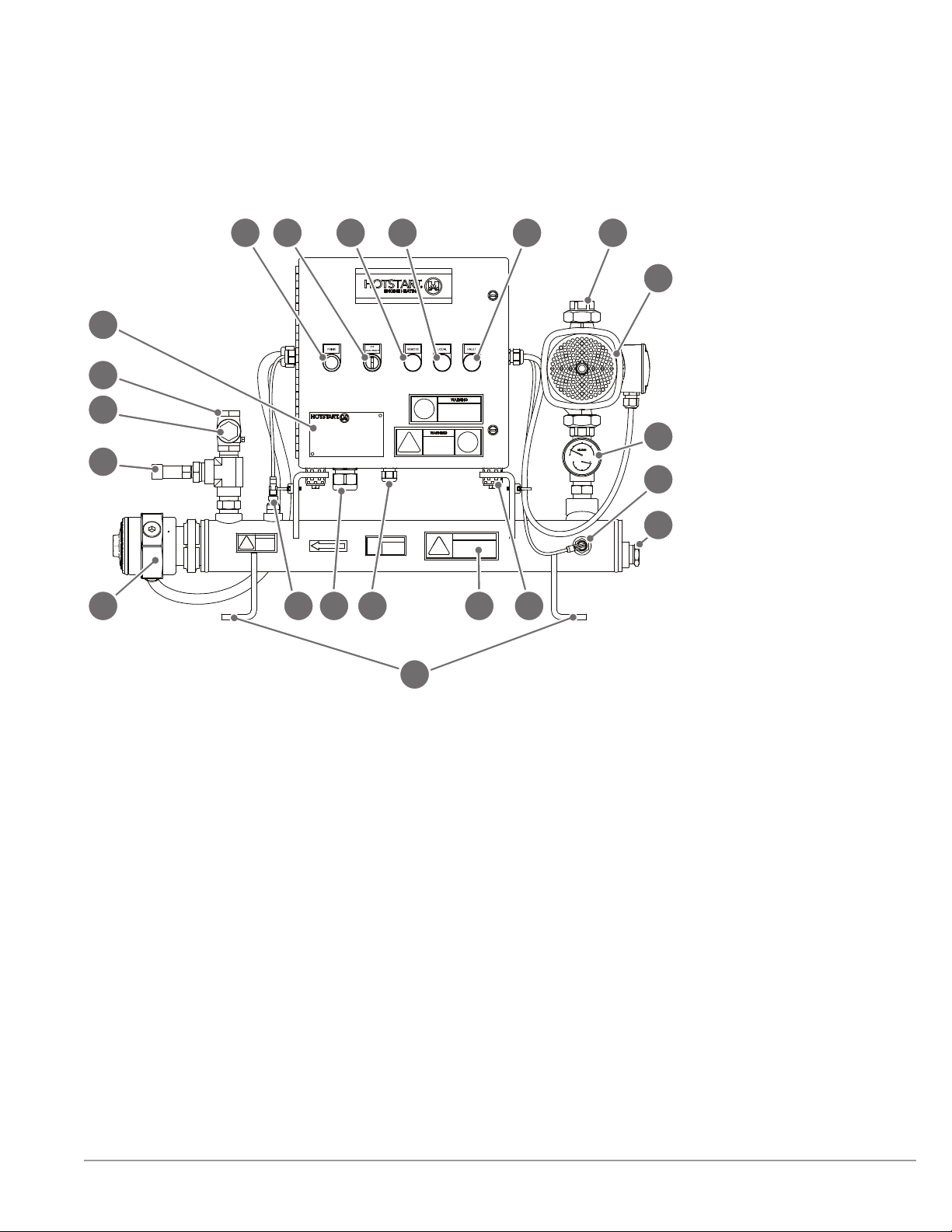
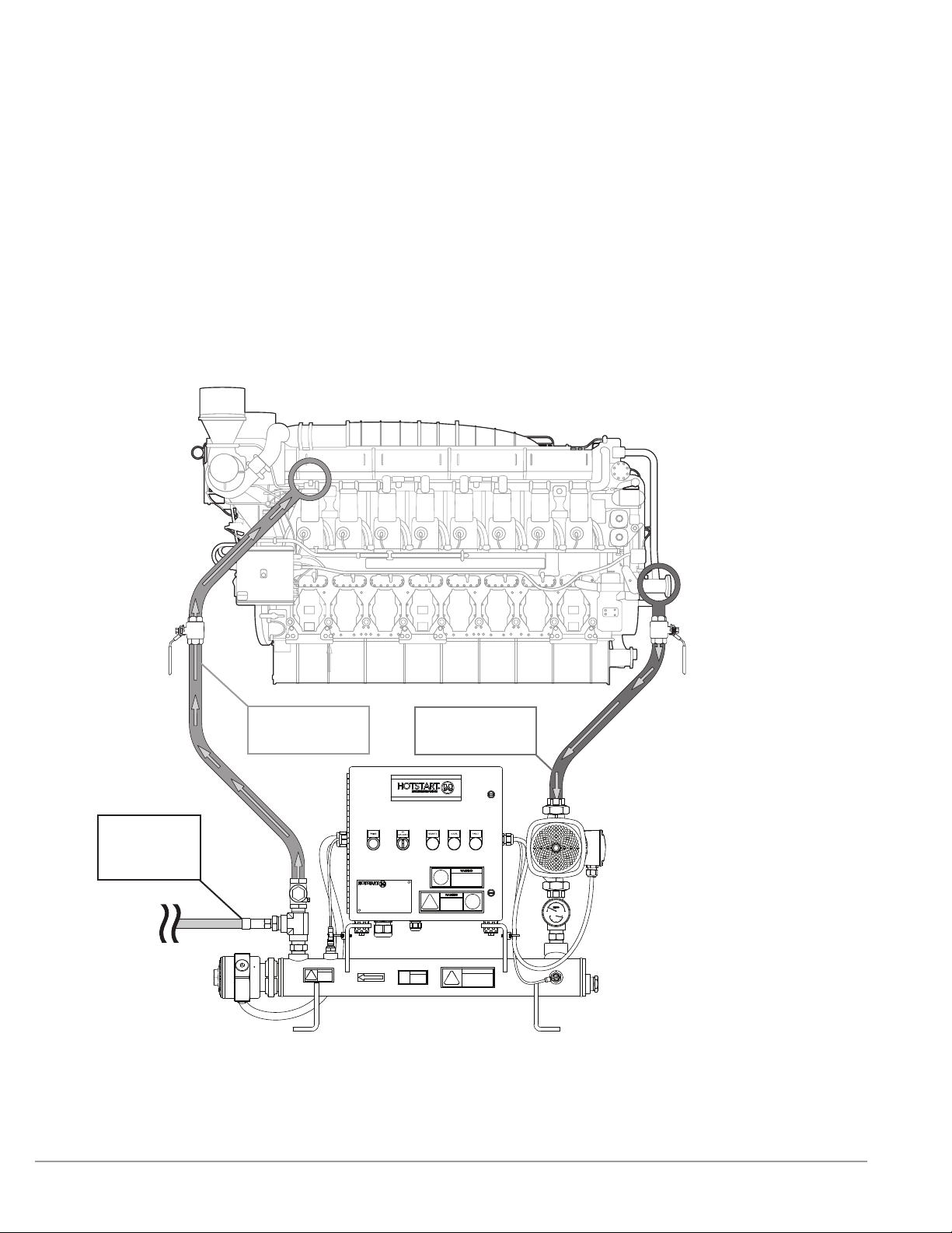
Figure 3. CMM/CLM system operation. Component illustrations
are for reference only and are not to scale. See part drawings for
dimensions and specications.
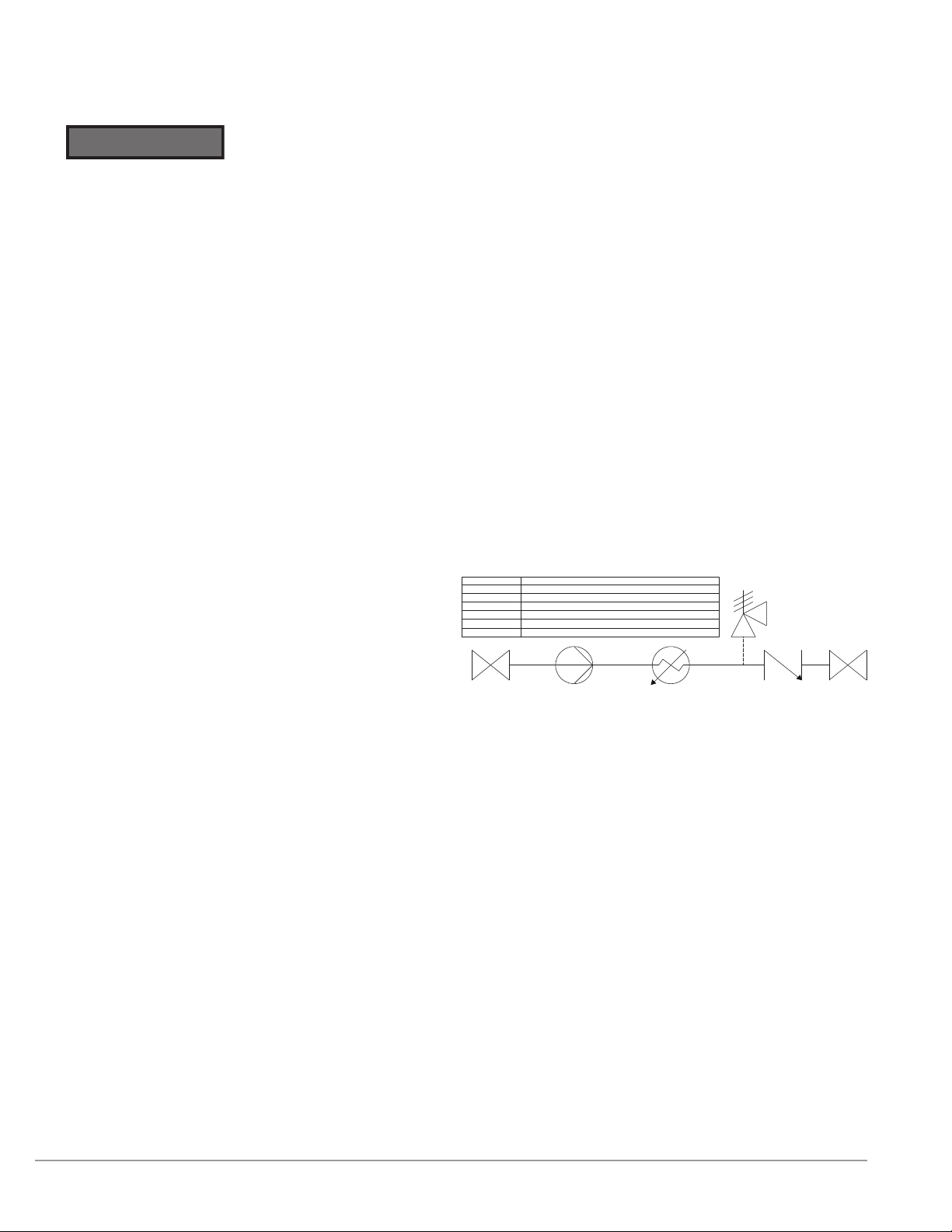
E-2E-1
V-1 V-4
V-2
COMPONENT
DESCRIPTION
V-1
V-2
USER SUPPLIED FULL FLOW ISOLATION VALVE
E-1
COOLANT PUMP
E-2
COOLANT HEATING ELEMENT
V-3
CHECK (NON-RETURN) VALVE
PRESSURE RELIEF VALVE
V-4
USER SUPPLIED FULL FLOW ISOLATION VALVE
V-3