ii installation & operation manual | ola heating system
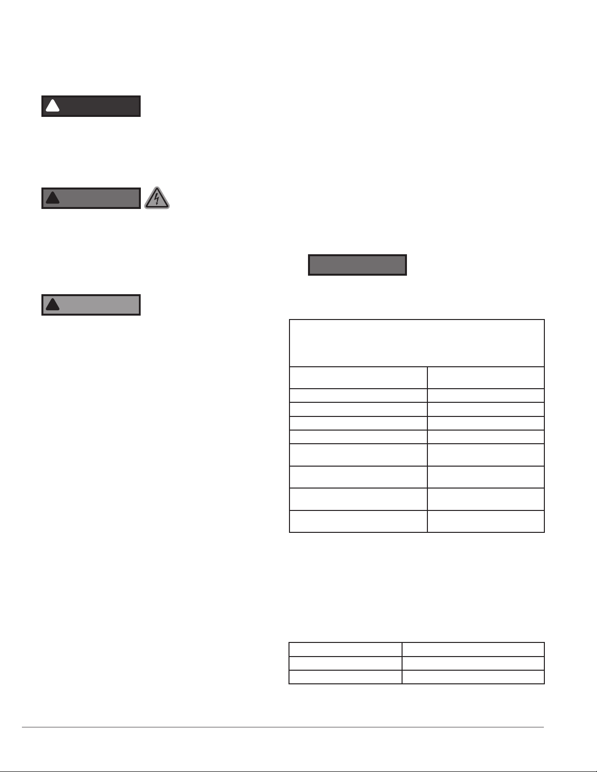
IMPORTANT SAFETY
INFORMATION
!
Hazardous voltage: Before wiring, servicing or cleaning
the heating system, turn off the power and follow your
organization’s lockout and tagout procedure. Failure to do
so could allow others to turn on the power unexpectedly,
resulting in harmful or fatal electrical shock.
!
Electrical hazard: All electrical work must be done by
qualied personnel in accordance with national, state
and local codes.
Electro-static discharge: Wipe all operators and hoses
with damp cloth to reduce potential for electro-static
discharge.
CAUTION
!
Read instructions carefully: The safety of any system
incorporating this equipment is the responsibility
of the assembler. The safe and proper use of this
equipment is dependent upon the installer following
sound engineering practices. If the equipment is
used in a manner not specied by the manufacturer,
the protection provided by the equipment may be
impaired. All applicable electrical safety standards
dened by local jurisdictions must be followed.
(Reference EU directive 2014/34/EU in EU countries.)
• Read carefully: Installers and operators of this
equipment must be thoroughly familiar with the
instructions in this manual before commencing work.
• Hot surfaces: Avoid contact with the system while it
is in service. Some surfaces may remain hot even if
the system is not energized.
• Proper lifting: Use proper lifting equipment and
rigging to move this equipment. Create a plan
before attempting to move. Proper lifting locations
are identied with labels on each system; use these
locations when lifting and mounting the system.
• Rotating equipment: The heating system can start
automatically and without warning. Avoid contact
unless a lockout at the service panel has been
installed.
• Grounding: The heating system must be connected
to a suitable ground (protective earthing conductor).
• Overcurrent limiting: The power supply must be
protected by a suitable overcurrent limiting device.
• Power disconnection: A means to disconnect the
heating system from the power supply is required.
HOTSTART recommends that a power switch or
circuit breaker be located near the heating system
for safety and ease of use.
• Flameproof joints: Flameproof joints are not
intended to be repaired in the eld. Do not attempt
to repair any ameproof joints that become
damaged.
• Bend radius: Do not adjust cable bend radius in the
eld. Cables are pre-wired to meet the minimum
requirements for bend radius. If a cable is moved
from factory positioning, adjust cable to ensure
minimum bend radius is 7 × (Ø) outer diameter of
the cable.
• Enclosure yield strength: The enclosures utilize
metric bolts that are Class 8.8 minimum and Class
A4-70 with a minimum yield strength of 600 MPa.
NOTICE
EU Countries only: Equipment rated for the conditions
listed in EN 601010-1 1.4.1 Ingress protection rating IP54.
(Special conditions for specic applications may apply.)
CERTIFICATIONS
Certications:
IECEx UL 18.0106X
Ex db IIA T3 Gb
DEMKO 18 ATEX
2107X
C0539 ` II 2 G Ex
db IIA T3 Gb
Standards used for
certications:
• IEC 60079-0:2011
and Corr. 1:2012
and Corr. 2:2013
• IEC 60079-1:2014
• EN 60079-0:2012
and A11:2013
• EN 60079-1:2014
• IEC TS 60079-46
Max/ Min. process uid temp. 0 °C to 80 °C
Ambient temp. -20 °C to 40 °C
Voltages 120 to 575 V AC, 50/60 Hz,1/3 phase
The following additional previous editions of Standards noted under the
“Standards” section of the Certicate were applied to integral Components
as itemized below. There are no signicant safety related changes between
these previous editions and the editions noted under the “Standards”
section.
Weg Induction Motors of Frame Size
90 to 132 IEC 60079-1 Edition 2007
Siemens Motors IEC 60079-0 Edition 2009
Siemens Motors IEC 60079-1 Edition 2007
ABB M3JP Motors IEC 60079-0 Edition 2009
ABB M3JP Motors IEC 60079-1 Edition 2007
CMP Products Limited TMC2X
Range of Cable Glands IEC 60079-1 Edition 2007
CMP Products Limited Cable Gland
Types PX** IEC 60079-1 Edition 2007
Adalet/Scott Fetzer Co. XCEX
Series Enclosures IEC 60079-0 Edition 2009
Adalet/Scott Fetzer Co. XCEX
Series Enclosures IEC 60079-1 Edition 2007