Hotsy 1800 Series User manual

8.916-993.0-AL 01/15/21
1800 Series
Hot Water - Electric - Gas Fired
Service Manual Stationary Pressure Washer
HONEYWELL
LOHI
CHAUD!
CHAUD!
MODELS: 1812SS
1.109-660.0
1832SS-208
1.109-661.0
1832SS
1.109-662.0
1835SS
1.109-663.0
1836SS
1.109-664.0
For the Hotsy Dealer nearest you,
consult our web page at
www.hotsy.com

2HOTSY 1800 GAS FIRED SERIES 8.916-993.0 - AL
Machine Data Label

3
Table of Contents
Machine Data Label . . . . . . . . . . . . . . . . . . . . . . . . . .2
Table of Contents . . . . . . . . . . . . . . . . . . . . . . . . . . . 3
How To Use This Manual . . . . . . . . . . . . . . . . . . . . . 4
Operations
Technical Specifications . . . . . . . . . . . . . . . . . . . . . .5
Maintenance
Smart Relay Instructions. . . . . . . . . . . . . . . . . . . . . . 6
Troubleshooting . . . . . . . . . . . . . . . . . . . . . . . . . . .10
Parts
Hotsy 1800 . . . . . . . . . . . . . . . . . . . . . . . . . . . . . . 14
Control Panel . . . . . . . . . . . . . . . . . . . . . . . . . . . . 18
Panel. . . . . . . . . . . . . . . . . . . . . . . . . . . . . . . . . . . 20
Coil Outlet . . . . . . . . . . . . . . . . . . . . . . . . . . . . . . . 22
Burner . . . . . . . . . . . . . . . . . . . . . . . . . . . . . . . . . . 24
Pump And Unloader . . . . . . . . . . . . . . . . . . . . . . . 26
Hose, Gun & Wand . . . . . . . . . . . . . . . . . . . . . . . . 28
Wiring Diagram 3PH Voltages . . . . . . . . . . . . . . . 30
HOTSY 1800 GAS FIRED SERIES 8.916-993.0 - AL

4
How To Use This Manual
This manual contains the following sections:
• How to Use This Manual
• Operations
• Maintenance
• Parts List
The HOW TO USE THIS MANUAL section will tell you
how to find important information for ordering correct
repair parts.
Parts may be ordered from authorized dealers. When
placing an order for parts, the machine model and
machine serial number are important. Refer to the
MACHINE DATA box which is filled out during the
installation of your machine. The MACHINE DATA box
is located on the inside of the front cover of this manual.
The model and serial number of your machine is
located on the back of the machine.
The OPERATIONS section is to familiarize the operator
with the operation and function of the machine.
The MAINTENANCE section contains preventive main-
tenance to keep the machine and its components in
good working condition. They are listed in this general
order:
• Smart Relay Instructions
• Water Inlet Solenoid
• Troubleshooting
The PARTS LIST section contains assembled parts
illustrations and corresponding parts list. The parts lists
include a number of columns of information:
•REF – column refers to the reference number
on the parts illustration.
•PART NO. – column lists the part number for
the part.
•QTY – column lists the quantity of the part used
in that area of the machine.
•DESCRIPTION – column is a brief description
of the part.
•NOTES – column for information not noted by
the other columns.
NOTE: If a service or option kit is installed on your
machine, be sure to keep the KIT INSTRUCTIONS
which came with the kit. It contains replacement parts
numbers needed for ordering future parts.
IMPORTANT: Refer to the Operators manual for
operations and WARNING instructions. This
manual is only for additional technical information.
Model:
Date of Purchase:
Serial Number:
Dealer:
Address:
Phone Number:
Sales Representative:
HOTSY 1800 GAS FIRED SERIES 8.916-993.0 - AL

5
Operations
Technical Specifications
Model #
Pump
Volume @
Pump Head
Pump
Pressure at
Pump Head
Burner Type Machine Voltage
Total
Machine
Amperage
Motor
Amps
1812SS
1.109-660.0
5.9 GPM
354 GPH 2500 PSI Natural Gas Fired
558,050 BTU/Hr. 230VAC/60Hz/1Ph 42 Amps 39 Amps
1832SS-208
1.109-661.0
6.0 GPM
360 GPH 3000 PSI Natural Gas Fired
558,050 BTU/Hr. 200VAC/60Hz/3Ph 36 Amps 41 Amps
1832SS
1.109-662.0
6.0 GPM
360 GPH 3000 PSI Natural Gas Fired
558,050 BTU/Hr. 230VAC/60Hz/3Ph 33 Amps 38 Amps
1835SS
1.109-663.0
6.0 GPM
360 GPH 3000 PSI Natural Gas Fired
558,050 BTU/Hr. 460VAC/60Hz/3Ph 19 Amps 19 Amps
1836SS
1.109-664.0
6.0 GPM
360 GPH 3000 PSI Natural Gas Fired
558,050 BTU/Hr. 575VAC/60Hz/3Ph 16 Amps 16.2 Amps
Model # Machine
Weight Shipping Weight Exhaust Stack
Size Machine Dimensions
1812SS
1.109-660.0 825Lbs 1070 Lbs 10” L 51” X W 31” X H 54”
1832SS-208
1.109-661.0 825Lbs 1070 Lbs 10” L 51” X W 31” X H 54”
1832SS
1.109-662.0 825Lbs 1070 Lbs 10” L 51” X W 31” X H 54”
1835SS
1.109-663.0 825Lbs 1070 Lbs 10” L 51” X W 31” X H 54”
1836SS
1.109-664.0 825Lbs 1070 Lbs 10” L 51” X W 31” X H 54”
HOTSY 1800 GAS FIRED SERIES 8.916-993.0 - AL

6
Maintenance
Smart Relay Instructions
Digital Timer (Optional)
The following are instructions on how to set the param-
eters on the digital timer in Programming Mode. To
define these settings please follow the steps below.
Setting the Clock:
1. Press the ESC key located next to the display
window and under the arrow key pad to access the
Parameter Assignment Menu.
2.Using the up/down arrow
keys ▲ or ▼, move the
cursor to highlight ‘Setup’
and press OK to accept.
3.Move the cursor to
highlight ‘Clock’ and press
OK to accept.
4.Move the cursor to
highlight ‘Set Clock’ and
press OK to accept.
NOTE: When setting time on
clock, use only military time.
5.Move the cursor to the value
wanting to be changed using
the left/right arrow keys or
, and change the value by
using the up/down arrow keys
▲ or ▼. When you are done
setting the time and date
press OK to accept your changes.
6. Press ESC three times to exit to the main menu.
Programming Instructions
The 5700/5800 can be configured to run in Time Delay
or Auto Start/Stop with lockout. Machines are factory
set with Auto Start/Stop with 4 hour Lockout. A Smart
Relay controls how the machine will operate by using
three internal timers; these timers are adjustable. The
following is a brief description of these timers:
Timer 1: ‘Lockout Timer’ (Time Delay)
• Timer 1 de-energizes (lockout) the machine if
not being used for a preset time. If machine
has ‘Locked out’ it can only be re-energize by
pressing the ‘Pump On’ switch. Timer 1 is
factory set to 4 hours.
Timer 2: ‘Auto Start/Stop Timer’
• Timer 2 allows the pump to run in bypass for a
preset time. If the pump runs in bypass longer
than the allotted time the timer will drop power
to the motor contactor and machine will be in
standby mode. Squeezing the gun trigger will
restart the pump (if Timer 1 has not locked out).
Timer 2 is factory set to 30 seconds.
Stop
Program
Setup
Network
Diagnostics
Msg Cong
Start Screen
Clock
LCD
Menu Language
Switch to OP
NTP
Set Clock
S/W Time
Set Clock
Mon. 10:15
YYYY-MM-DD
HOTSY 1800 GAS FIRED SERIES 8.916-993.0 - AL
Mo 10:15
2006-10-13
S
WX
T
ESC OK
Display Screen
Arrow
Key Pad

7
Maintenance
Timer 3: ‘Reset Delay Timer’
• Timer 3 controls how long the pump must run
before resetting the ‘Lockout Timer’ (Timer 1).
This allows the pump to run long enough to re-
pressurize the system if there is pressure loss
when not in use. Timer 3 is factory set to 15
seconds.
To change to the parameters of the internal timers in
the Smart Relay complete the following steps:
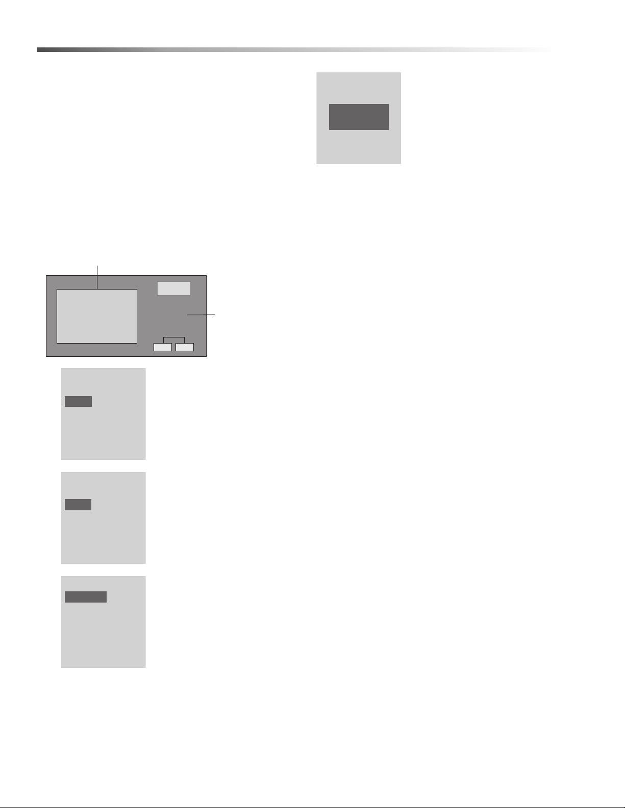
1. Turn on the power to the machine but do not press
the start switch. Remove the front panel and then
the control panel cover. NOTE: Use extreme
CAUTION when reaching into the control box,
the machine has live power. Once powered the
Smart Relay window will display the following
screen, see figure 1 (if screen does not appear
press the left/right arrow keys or until correct
screen appears).
2. Press the ESC key located next to the display
window and under the arrow key pad to access the
Menu.
3.Using the up/down arrow
key ▲ or ▼, move the
cursor to highlight ‘Program’
and press OK to confirm.
4.Using the up/down arrow
key ▲ or ▼, move the
cursor to highlight ‘Set
Parameter’ and press OK to
confirm.
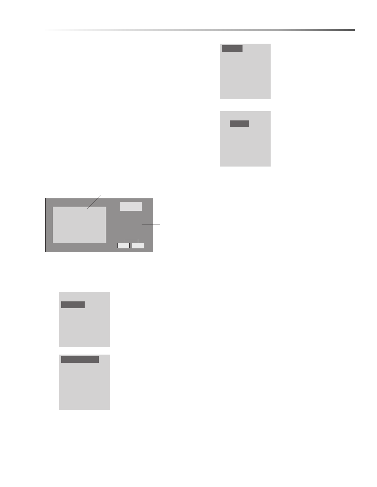
5.The display window will
display the Timers.
Highlight the Timer desired
to change and press OK.
NOTE: Ta is the
accumulator timer and T is
the adjustable timer (the
variable that changes).
6.Highlight the T field and
press OK to edit the value.
Use the left/right arrow keys
or , move the cursor to
the used the up/down arrow
keys ▲ or ▼ to change this
value. Each timer has
optional units of time in
seconds (s), minutes (m),
and hours (h). To change
the unit of time using the arrows up/down keys ▲
or ▼. Once all values have been set press, OK to
accept and ESC to back up to the Timer selection
menu.
Repeat steps 5 and 6 for the other times if needed.
When finished press ESC three times to go to the main
menu.
Stop
Program
Setup
Network
Diagnostics
Set Parameter
Prog Name
Timer-1
Timer-2
Timer-3
Timer-1 1/1
T= 04:00h
Ta= 00:00
HOTSY 1800 GAS FIRED SERIES 8.916-993.0 - AL
S
WX
T
ESC OK
1:
0.. 123456789
1..0123456789
2..01234
Fig. 1
Display Screen
Arrow
Key Pad

8
Maintenance
Factory Set Parameters (Auto Start/Stop with Lockout)
Time Delay Parameters
Preventative Maintenance
TIMER VALUE DESCRIPTION
Timer 1 04:00 Hours Turns machine off after 4 hours of non-use. To restart push the
‘Pump On’ switch.
Timer 2 30:00 Seconds Pump will run in bypass for 30 seconds before shutting off, machine
is still in standby mode. Pulling the gun trigger will restart the pump.
Timer 3 15:00 Seconds In case of pressure loss when machine is in standby, the pump can
run up to 15 seconds before resetting ‘Timer 1’ (lockout)
TIMER VALUE DESCRIPTION
Timer 1 03:00 Minutes When machine is not in use, pump will run in bypass for 3 minutes
and shut off. To restart push the ‘Pump On’ switch.
Timer 2 01:00 Hours To operate in time delay mode timer 2 must be deactivated. This is
done by setting timer 2 to value greater than timer 1.
Timer 3 15:00 Seconds Pump must run more than 15 seconds to reset timer 1.
Pressure Relief Valve Open annually to remove any sediment.
HOTSY 1800 GAS FIRED SERIES 8.916-993.0 - AL

9
Maintenance
Optional — Water Inlet Solenoid
A water inlet solenoid can be added to the machine that
will open only when the machine is running or in
standby. The solenoid closes when the machine is off to
prevent possible water overflow when unattended.
Installation
• Connect a 24V/AC normally closed solenoid on
the water inlet, contact local Hotsy dealer for
solenoid options.
• Connect solenoid to the remote terminal using
16 ga minimum wire
• Wire solenoid to remote terminal according to
figure below
Before powering up machine, fill float tank to prime the
system.
HOTSY 1800 GAS FIRED SERIES 8.916-993.0 - AL
Detergent Solenoid Wiring Schematic

10
Maintenance
Troubleshooting
SYMPTOM POSSIBLE CAUSES CORRECTIVE ACTION
PRESSURE
WASHER
WILL NOT
RUN
Pump switch in OFF position Place switch in ON position.
Power supply disconnected Connect power supply.
Fuse blown or circuit breaker
tripped in electrical supply line
Replace fuse or reset circuit breaker. Use only
circuits of adequate capacity.
Motor circuit overload tripped Allow sufficient time for motor to cool down. Place
pump switch in ON position.
PRESSURE
WASHER
RUNS BUT
WON’T SPRAY
Trigger of trigger gun released Squeeze trigger.
Water supply not turned on Open water supply valve.
Clogged pressure nozzle Clean pressure nozzle opening.
Inlet water screen clogged Check screen and clean if necessary.
Pump sucking air Fill the detergent container and check for loose
hose clamps or fittings.
LOW SPRAY
PRESSURE
AT NOZZLE
Inadequate water supply
Fully open faucet. Check for kinked or damaged
hose. Use 5/8" minimum hose. Check for debris
clogging inlet screen.”
Partially clogged or damaged
pressure nozzle Clean or replace.
Air being drawn through
detergent inlet line
Refill detergent container. Ensure that pick-up
screen is fully immersed.
UNEVEN
SPRAY
PATTERN
Partially clogged or damaged
pressure nozzle Clean or replace.
PRESSURE
WASHER
WILL NOT
PRODUCE
HOT WATER
Burner switch in OFF position Place switch in ON position.
Gas valve switch in OFF
position Place switch in ON position.
Inadequate fuel supply Check fuel supply.
Pump switch turned off Pump must be running before burner will light.
Inadequate water supply
Fully open faucet. Check for kinked or damaged
hose. Use 5/8" minimum hose. Check for debris
clogging inlet screen.
Trigger of trigger gun released Squeeze trigger. Water must be spraying for burner
to light.
Thermostat set too low, or
defective Raise thermostat setting. Replace if defective.
Manual gas valve not open Turn ON gas valve
Defective gas valve Replace gas valve.
HOTSY 1800 GAS FIRED SERIES 8.916-993.0 - AL

11
Maintenance
SYMPTOM POSSIBLE CAUSES CORRECTIVE ACTION
POOR OR
NO DETERGENT FLOW
Inadequate detergent supply
Refill detergent container. Ensure that pick-up
screen is fully immersed and detergent container
is at or above the level of the pump.
Detergent screen or hose clogged Clean. Always start with a a clean detergent
container.
Clogged detergent injector check
valve Clean check valve at detergent injector.
POOR
CLEANING
Improper detergent concentration or
mixing
Mix detergent per manufacturer's instructions.
Ensure that powdered detergents are fully
dissolved.
Wrong detergent for the
application. Select appropriate detergent.
Detergent valve not opening Check that handle or knob is not slipping on shaft.
UNLOADER CYCLES
WHEN TRIGGER
GUN IS OPENED
OR CLOSED
Air in system Open and close trigger gun several times.
Unloader defective Replace if defective.
Water leak between unloader valve
and trigger gun
Check fittings, hose, and trigger gun for leaks.
Repair or replace.
BURNER
SMOKES OR HAS
OBNOXIOUS ODOR
Stack restriction See Venting under Installation.
PRESSURE
RELIEF VALVE
IS LEAKING
Excessive pressure due to
defective unloader valve Replace unloader valve.
Defective relief valve Replace relief valve.
Dirty relief valve Clean relief valve seat.
HOTSY 1800 GAS FIRED SERIES 8.916-993.0 - AL

12
Notes
HOTSY 1800 GAS FIRED SERIES 8.916-993.0 - AL

13
Parts
Parts
(1.109-660.0, 1.109-661.0, 1.109-662.0,
1.109-663.0, 1.109-664.0)
HOTSY 1800 - GAS FIRED SERIES
HOTSY 1800 GAS FIRED SERIES 8.916-993.0 - AL

14
Hotsy 1800
HONEYWELL
LOHI
CHAUD!
CHAUD!
4
6
9
11
14 15
13
12
5
20
1
3
10
8
2
7
11
10
52
50 50
52
See
Burner
Assy
See
Coil Outlet
Assy
37
53
18
11
36
33
17
18
11
27
HOTSY 1800 GAS FIRED SERIES 8.916-993.0 - AL

15HOTSY 1800 GAS FIRED SERIES 8.916-993.0 - AL
Hotsy 1800
REF PART NO. QTY DESCRIPTION NOTES
1 8.912-064.0 1 TOP HAT ASSY, 24 X 10
2 9.800-006.0 2 LABEL, "HOT/CALIENTE" WITH ARROWS WARNING
3 8.725-507.0 1 INSULATION 23.5" OD X 10.75" ID, FIBERGLASS
F
OF
°F
10-02033
0
20
165
130
95
235
270
300
11
26 34
21
19
48
11
45
47
10
10
55
43
46
59
54
11
51
58
39
56
40
18
28
18
44
60
30
42
18
23
25
22
11
18
11
See
Control
Panel
Assy
See
Pump
Assy
See
Float
Tank
Assy
11
18
28
11
38
29
28
11
28
18
11
11
18 10
11
49
11
10
1011 35
62
31
28
61
61
57
16
32
See
Unloader
Assy
41
41
24

16
Hotsy 1800
REF PART NO. QTY DESCRIPTION NOTES
4 8.719-940.0 1 RING, INSULATION RETAINER
5 8.912-084.0 1 COIL ASSY, GAS, 22"
6 8.725-505.0 1 INSULATION 70" X 29.5", FIBERGLASS
7 9.802-825.0 4 CLIP, RETAINING U-TYPE
8 8.704-659.0 1 LABEL, HOTSY LOGO, 5 X 11
9 8.900-990.0 1 LABEL, INSTRUCTION, WARNING
(PICTORIAL/TEXT)
10 9.802-720.0 24 BOLT, 3/8” X 1", NC HH
11 9.802-807.0 66 WASHER, 3/8”, SAE, FLAT
12 8.757-231.0 1 NIPPLE STEEL 1/2 NPTF X 3 W/SLNT
13 8.757-615.0 1 TEE STEEL 1/2" NPTF (F)
14 8.757-625.0 1 PLUG 1/2 NPTF SQUARE HEAD
15 8.757-508.0 1 ADAPTER STEEL 1/2 SAE (M) X 1/2 NPTF (M)
16 8.916-791.0 1 BRACKET, TENSIONER BASE
17 9.802-814.0 1 WASHER, 3/8”, LOCK, SPLIT RING
18 9.802-779.0 39 NUT, 3/8” ESNA 1832SS-208, 1832SS,
1835SS, 1836SS
19 8.715-611.0 1 PULLEY, 3B36SH
20 8.916-749.0 1 WLMT, FRAME, COIL 30”
21 8.916-750.0 1 WLMT, FRAME, WASHER TOP
22 8.925-632.0 1 HARNESS CORD MOTOR 1800/57/5800 6/4 1832SS
- 8.925-634.0 1 HARNESS CORD MOTOR 1800/57/5800 4/4 1832SS-208
- 8.925-638.0 1 HARNESS CORD MOTOR 1800/57/5800 10/4 1835SS
- 8.925-777.0 1 HARNESS CORD MOTOR 18/57/5800 12/4 1836SS
- 8.925-640.0 1 HARNESS CORD MOTOR 1800/57/5800 8/3 1812SS
23 8.716-564.0 1 STRAIN RELIEF,1’ GREY 1832SS
- 8.758-002.0 1 STRAIN RELIEF CG75-750 3/4" YELLOW 1812SS
- 9.803-279.0 1 STRAIN RELIEF,CG100-750,1” YEL(10-4CORD) 1835SS, 1836SS
- 9.803-975.0 1 STRAIN RELIEF,CG100-1050,1'BLK(4/4 CORD) 1832SS-208
24 9.802-259.0 24" HOSE, 1/2”, PUSH-ON
25 9.803-280.0 1 LOCK NUT, 1” 1832SS-208, 1832SS,
1835SS, 1836SS
- 9.802-523.0 1 LOCKNUT, 3/4" CONDUIT 1812SS
26 8.918-225.0 1 HOSE, 1/2” X 28", 2 WIRE, LOW PRESSURE
27 8.916-973.0 1 PANEL, FIRE WALL
28 6.390-126.0 5 CLAMP, HOSE,.46-.54 ST
29 9.802-252.0 13" HOSE 1/4” BRAIDED VINYL
30 9.802-252.0 50" HOSE, 1/4" BRAIDED VINYL
31 8.707-058.0 1 STRAINER, 1/4 BRASS W/CHECK VALVE
32 8.753-882.0 1 COVER, EXTENSION, 1 GANG
HOTSY 1800 GAS FIRED SERIES 8.916-993.0 - AL

17HOTSY 1800 GAS FIRED SERIES 8.916-993.0 - AL
Hotsy 1800
REF PART NO. QTY DESCRIPTION NOTES
33 8.901-135.0 1 LABEL, CAUTION WINTERIZE
34 8.918-225.0 1 HOSE, 1/2" X 28", 28 WIRE, PRESSURE LOOP
35 8.917-016.0 1 LABEL, MOTOR ROTATION, CLOCKWISE
36 8.917-022.0 1 HALF-WRAP, OUTER, OUTLET, 24"
37 8.917-023.0 1 HALF-WRAP, OUTER, 24"W
38 9.802-188.0 1 VALVE, METERING, 1/4" HOSE
39 8.716-564.0 1 STRAIN RELIEF, 1" GREY 1832SS
- 9.803-279.0 1 STRAIN RELIEF,CG100-750,1" YEL(10-4 CORD) 1812SS, 1835SS,
1836SS
- 9.803-975.0 1 STRAIN RELIEF,CG100-1050,1'BLK(4/4 CORD) 1832SS-208
40 8.900-515.0 1 LABEL, 208V 3 PH 1832SS-208
- 9.800-023.0 1 LABEL, 230V 3 PH 1832SS
- 9.800-024.0 1 LABEL, 460V 3 PH 1835SS
- 8.900-516.0 1 LABEL, 575V, 3 PH 1836SS
- 9.800-025.0 1 LABEL, 230V 1 PH 1812SS
41 9.802-151.0 2 SWIVEL, 1/2” JIC FEMALE, PUSH-ON
42 9.802-152.0 2 SWIVEL, 3/4” SAE FEMALE, PUSH-ON
43 8.749-975.0 1 TENSIONER (HARDWARE INCLUDED)
44 8.749-965.0 1 BANDED BELT, BX42 X 3
45 8.715-618.0 1 PULLEY, 3BK80H
46 8.750-103.0 1 PULLEY, 3TB46
47 9.802-403.0 1 BUSHING, H X 25MM
48 9.803-980.0 1 BUSHING, P1 X 1-5/8” 1832SS-208, 1832SS,
1835SS, 1836SS
- 8.715-650.0 1 BUSHING, P1 X 1-3/8" 1812SS
49 8.749-973.0 1 BUSHING, IDLER (HARDWARE INCLUDED)
50 9.802-776.0 7 NUT, 5/16 ESNA
51 8.756-429.0 1 MOTOR, 15HP 3PH, 230/460V, 1800RPM 1832SS, 1835SS
- 8.756-430.0 1 MOTOR, 15HP 3PH, 575V, 1800RPM 1836SS
- 8.715-110.0 1 MOTOR, 10HP/230V/1PH 1812SS
- 8.755-600.0 1 MOTOR, 15HP 3PH, 200V, 1775RPM 1832SS-208
52 8.719-000.0 7 WASHER, 5/16" X 1-1/4", FENDER, SAE
53 9.802-754.0 8 SCREW, 1/4" X 1/2" WHIZ
54 8.916-752.0 1 WLMT, SLIDE, MOTOR BASE 1832SS-208, 1832SS,
1835SS, 1836SS
- 8.917-130.0 1 WLMT, MOUNT, MOTOR, 10 HP 1812SS
55 8.916-748.0 1 WLMT, FRAME, WASHER BASE
56 8.706-117.0 1 NIPPLE, 1", CLOSE, BLACK PIPE
57 8.716-339.0 1 BOX, ELEC 4 X 2, 3 HOLE 1"
58 9.802-483.0 1 COVER, METAL, 2" X 4", WATERPROOF
59 8.718-650.0 4 BOLT, 3/8" X 1/2", NC HH
60 9.802-261.0 28" HOSE, 3/4", PUSH-ON
61 8.757-199.0 2 HOSE BARB, 1/4" BARB x 1/4" M-NPTF, BRASS
62 9.802-252.0 8 FT. HOSE, 1/4" BRAIDED VINYL

18
Control Panel
REF PART NO. QTY DESCRIPTION NOTES
1 8.916-922.0 1 DOOR, CONTROL PANEL
2 8.718-936.0 10 SCREW, #8 X 1/2”, PHILLIPS PLATED, TEK
3 9.803.613.0 1 HONEYWELL, IGNITION CONTROL
4 8.716-883.0 1 TRANSFORMER 208/230/460 1812SS, 1832SS-208,
1832SS, 1835SS
- 8.716-884.0 1 TRANSFORMER 575 1836SS
5 8.916-931.0 1 LABEL, CONTROL PANEL
6 9.802-776.0 4 NUT, 5/16”, ESNA, NC
7 8.718-980.0 4 WASHER, 5/16” FLAT, SAE
8 8.916-783.0 1 PLATE, STAND-OFF, ELECTRICAL
9 8.916-914.0 1 WLMT, BOX, ELECTRICAL
10 8.716-564.0 2 STRAIN RELIEF,CG100-950 1' GRY(6/4 CORD) 1832SS
- 9.803-279.0 2 STRAIN RELIEF,CG100-750,1" YEL(10-4 CORD) 1812SS, 1835SS, 1836SS
- 9.803-975.0 1 STRAIN RELIEF,CG100-1050,1'BLK(4/4 CORD) 1832SS-208
11 8.750-097.0 1 KNOB, THERMOSTAT
12 8.718-779.0 2 SCREW, 4 MM X 6 MM, PAN HEAD
13 8.712-190.0 1 PLATE, THERMOSTAT, PLASTIC COVER
14 8.750-095.0 1 THERMOSTAT
15 8.716-598.0 3 STRAIN RELIEF, 18-.31 (.51 HOLE)
16 9.802-514.0 1 STRAIN RELIEF, LT, Str, 1/2 NPT,.23-.45D
17 9.802-283.0 1 HOUR METER
HOTSY 1800 GAS FIRED SERIES 8.916-993.0 - AL
GROUND
GROUND
OFF
F°
10-02033
200
165
130
95
235
270
300
29
3
9
13
11
10
12
4
67
28
145
8
27
33
32
41
19, 20,
21, 35 34
2
40
30
23
27
46
43
42
39, 49
24
36
43
50
47
41
42 42
2
22, 37
25, 26
5
17
18
2
36
36
36
52
53
16
31
14
44
38 To Junction Box
From
Motor
15
48
48
2
40

19HOTSY 1800 GAS FIRED SERIES 8.916-993.0 - AL
Control Panel
REF PART NO. QTY DESCRIPTION NOTES
18 8.716-037.0 2 SWITCH, ROCKER, 10A/250V15A/125V, 24V
19 8.749-979.0 1 JUMPER, BAR, 3-5 BU NOT SHOWN
20 8.749-978.0 1 JUMPER, BAR, 3-5 RD NOT SHOWN
21 8.749-977.0 3 JUMPER, BAR, 2-5 GY NOT SHOWN
22 8.921-218.0 1 Q BAR, PLC NOT SHOWN
23 9.800-016.0 1 LABEL, DISCONNECT POWER
24 8.704-998.0 1 STRAP, 14"
25 9.803-663.0 2 FUSE, KTK-R2 (AMP), 600V MIDGET FUSE
- 9.802-462.0 2 FUSE, KTK-R-1/2, 600V 1836SS
26 8.716-199.0 1 FUSE, FNM-6.25
27 9.800-040.0 2 LABEL, GROUND
28 8.713-086.0 1 GROUND LUG, 2 HOLE
29 9.802-778.0 4 NUT, WHIZ LOC, 5/16 FLANGE
30 9.802-457.0 6-1/2” DIN RAIL, 35 MM
31 9.802-457.0 3" DIN RAIL, 35 MM
32 8.724-269.0 1 CONTACTOR, DP C25DNY152TL, 25 AMP 1835SS, 1836SS
- 8.724-283.0 1 CONTACTOR, 50 AMP 1812SS, 1832SS-208, 1832SS
33 8.724-304.0 1 OVERLOAD, 16.0 - 24.0 1835SS, 1836SS
- 8.724-307.0 1 OVERLOAD, 40.0 - 57.0 1812SS, 1832SS, 1832SS-208
34 8.749-976.0 13 TERMINAL BLOCK
35 8.749-980.0 1 END CAP, TERMINAL BLOCK
36 9.804-595.0 4 END BRACKET
37 8.756-361.0 1 RELAY, SMART, 24V, 8I/4O, FS
- 8.918-471.0 1 PROGRAMMED, SMART RELAY, STATIONARY PRE PROGRAMED REPLACEMENT
PART
38 8.925-633.0 1 HARNESS CORD POWER 1800/57/5800 6/4 1832SS
- 8.925-635.0 1 HARNESS CORD POWER 1800/57/5800 4/4 1832SS-208
- 8.925-639.0 1 HARNESS CORD POWER 1800/57/5800 10/4 1835SS
- 8.925-778.0 1 HARNESS CORD POWER 18/27/5800 12/4 1836SS
- 8.925-641.0 1 HARNESS CORD POWER 1800/57/5800 8/3 1812SS
39 8.716-394.0 1 TERMINAL BLOCK, 14 POLE
40 8.718-937.0 4 SCREW, #8 X 3/4”, PHILLIPS, ZINC PLATED, TEK
41 9.802-700.0 3 BOLT, 1/4” X 3/4” NC HH
42 9.802-802.0 4 WASHER, FLAT, 1/4”
43 9.802-773.0 2 NUT, 1/4”, ESNA
44 8.905-701.0 1 LABEL, TERMINAL BLOCK
45 8.900-515.0 1 LABEL, 208V 3PH 1832SS-208
- 9.800-023.0 1 LABEL, 230V 3PH 1832SS
- 9.800-024.0 1 LABEL, 460V 3PH 1835SS
- 8.900-516.0 1 LABEL, 575V 3PH 1836SS
- 9.800-525.0 1 LABEL, 230V 1PH 1812SS
46 9.802-518.0 1 STRAIN RELIEF, 3/4”
47 9.802-771.0 1 SCREW, 10/32” X 3/4” BH SOC
48 9.802-696.0 2 NUT, 10/32” KEP
49 8.716-451.0 3 TERMINAL, JUMPER, SPADE
50 9.803-280.0 2 LOCKNUT, 1" CONDUIT
51 9.807-875.0 1 PLC LOGIC, STATIONARY HOT WATER, FS NOT SHOWN
52 9.802-105.0 1 PLUG, 7/8', HOLE
53 8.706-755.0 1 BUSHING, .875, P/N 2119

20
Panel
REF PART NO. QTY DESCRIPTION NOTES
1 8.916-761.0 1 PANEL, COVER, HOTSY, BURNER 16 X 30
2 8.916-762.0 1 PANEL, COVER, 44 X 17
3 8.916-763.0 1 PANEL, COVER, 44 X 27
4 8.916-764.0 1 PANEL, COVER, BACK 44 X 20
5 8.916-765.0 1 PANEL, COVER, SIDE 30 X 28
6 8.916-766.0 2 PANEL, COVER, BURNER 16 X 30
HOTSY 1800 GAS FIRED SERIES 8.916-993.0 - AL
14
13
3
9
12
11
8
10
9
5
2
16
8
4
15
15
18
17
10
22
20
23
24
25
19
19
Location Of
1st Serial
Plate
Location Of 2nd Serial Plate,
Inside Same Panel That 1st
Serial Plate Is Attached To
26 (2x 27”)
26 (2x 16”)
7
19
(42”)
26 (4x 10”)
26 (26”)
26 (9”)
26 (26”)
26 (14”)
19 (42”)
26 (2x 16”)
26
(6x 10”)
Other manuals for 1800 Series
3
This manual suits for next models
10
Table of contents
Other Hotsy Pressure Washer manuals

Hotsy
Hotsy 1200 Series User manual

Hotsy
Hotsy 771 User manual

Hotsy
Hotsy 555 HE User manual

Hotsy
Hotsy EP Series User manual

Hotsy
Hotsy 1720 User manual

Hotsy
Hotsy 800 Series User manual

Hotsy
Hotsy 1200 Series User manual

Hotsy
Hotsy 5645 User manual

Hotsy
Hotsy 680SS Service manual

Hotsy
Hotsy EP-2010 User manual

Hotsy
Hotsy 555 HE Service manual

Hotsy
Hotsy 965SS User manual

Hotsy
Hotsy 680SS Service manual

Hotsy
Hotsy 790SS Service manual

Hotsy
Hotsy 1.109-691.0 User manual

Hotsy
Hotsy HHD 5/30 G User manual

Hotsy
Hotsy 1075BE Series User manual

Hotsy
Hotsy Trailer 3500 User manual

Hotsy
Hotsy 558 User manual

Hotsy
Hotsy BD-373539 User manual