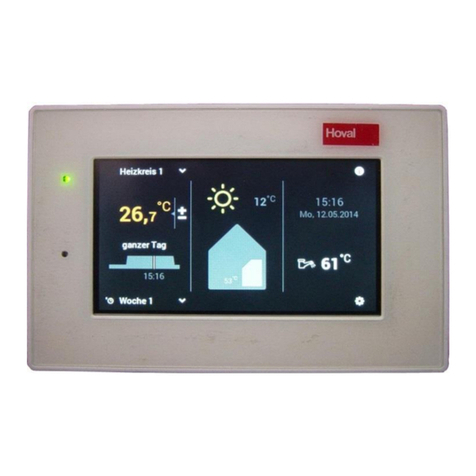
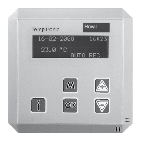
Hoval TopTronic C-SYS User manual

System control for TopVent®C-SYS
Operating Manual
TopTronic®C
System control for
TopVent®C-SYS
4 216 689-en-01

1 Use 3
1.1 Intended use .................................................................. 3
1.2 User groups ................................................................... 3
2 Basic principles 4
2.1 Operating elements........................................................ 4
2.2 Display elements............................................................ 5
2.3 Abbreviations ................................................................. 5
2.4 Operating modes ........................................................... 6
2.5 System overview............................................................ 7
2.6 Entering password ......................................................... 7
2.7 Logging off..................................................................... 8
2.8 Setting date and time ..................................................... 8
3 Menu tree 9
4 Operating examples 11
4.1 Switching operating modes ...........................................11
4.2 Setting the room temperature setpoint ......................... 12
4.3 Programming the weekly calendar ............................... 13
5 Info menus 15
5.1 Info menu zone ............................................................ 15
5.2 Info menu supply air unit.............................................. 16
5.3 Info menu recirculation unit.......................................... 17
6 Operating menu zone 18
7 Alarms 19
7.1 Alarm display ............................................................... 19
7.2 Alarm processing ......................................................... 20
7.3 Alarm list ...................................................................... 20
8 Adjustable parameters 23
2
TopTronic®C
System control for TopVent®
4 216 689-en-01
Content

1 Use
1.1 Intended use
The zone controller with operating panel is an operator terminal making it simple
to operate and monitor decentralised Hoval indoor climate systems. It gives users
access to all information and settings of the TopTronic®C control system that are
necessary for normal operation:
Display and setting of operating modes
Display of temperatures and setting of the room temperature set values
Display and programming of the weekly calendar
Display and handling of alarms
Password protection
Intended use also includes compliance with the operating instructions. Any usage
over and above this use is considered to be not as intended. The manufacturer
can accept no liability for damage resulting from improper use.
1.2 User groups
There are 2 operator levels:
Operator level User group Access rights Access
Guest Untrained users Read rights free
user Trained users Read rights
Write rights
– Calendar
– Set values
– Operating
parameters
– Alarm processing
Protected by a password
Factory setting
password:
12345
3
TopTronic®C
System control for TopVent®
Use
4 216 689-en-01

2 Basic principles
2.1 Operating elements
The device is operated via a 8-line display and 6 keys:
Icon Meaning
Call up alarm list (press shortly)
Reset alarms (press key and hold it down for 3 seconds)
Key ashes: A new alarm has occurred.
Key lights up: An already acknowledged alarm is still present.
Open activated function fields
Call up Main menu
Save/delete switching points
Return to the overview
Exit without saving
Navigate upwards in multi-page menus
Increase values
Navigate to the next function field
Confirm values
Navigate downwards in multi-page menus
Decrease values
4
TopTronic®C
System control for TopVent®
Basic principles
4 216 689-en-01

2.2 Display elements
Icons in general
Icon Meaning
Guest operator level
user operator level
iSystem info
!Alarm
Symbol ashes: A new alarm has occurred.
Symbol lights up: An already acknowledged alarm is still present.
Icons in the alarm list
Icon Meaning
Displays an alarm that must be acknowledged.
!Displays an acknowledged alarm in which the error has not yet been rectified.
*Displays a temporary alarm that must be acknowledged.
2.3 Abbreviations
Category Abbreviation Meaning
Unit types REMU Supply air units
RECU Recirculation units
Zone operating
modes
AUTO Automatic mode
CPR Cooling protection
DES Destratification
ES Forced off (zone)
EXT External control by building management system
NCS Night cooling
OPR Overheat protection
OPTC Start optimisation cooling
OPTH Start optimisation heating
REC Recirculation
REC1 Recirculation speed 1
SA1 Supply air speed 1
SA2 Supply air speed 2
ST Standby
Unit operating
modes
L_AUTO Automatic mode
L_DEL_REC Follow-on drying cooling coil (local)
L_DOOR Air curtain (local)
L_ES Forced off (local)
L_FCD Emergency operation (local)
L_OFF Off (local)
L_REC Recirculation (local)
L_REC1 Recirculation speed 1 (local)
L_SA1 Supply air speed 1 (local)
L_SA2 Supply air speed 2 (local)
5
TopTronic®C
System control for TopVent®
Basic principles
4 216 689-en-01

2.4 Operating modes
Code Operating mode
REMU
RECU
REC Recirculation
On/Off recirculation operation with TempTronic algorithm: During heat or
cool demand, the unit draws in room air, heats or cools it and blows it back
into the room. The room temperature set value day is active. The flow rate is
controlled in 2 stages.
● ●
DES Destratication:
To avoid heat build-up under the ceiling, it may be appropriate to switch
on the fan when there is no heat or cool demand (either in permanent
operation or in on/off operation depending on air temperature under the
ceiling, as desired).
● ●
REC1 Recirculation speed 1
The same as REC, but the unit operates only at speed 1
(low air flow rate)
● ●
DES Destratication:
The same as for REC, but the unit operates only at speed 1
● ●
SA2 Supply air speed 2
The unit blows fresh air into the room. The fresh air ratio is adjustable.
Heating/cooling is controlled according to the heat/cool demand. The room
temperature set value day is active. The unit operates at speed 2 (high air
flow rate).
●
SA1 Supply air speed 1
The same as SA2, but the unit operates at speed 1 (low air flow rate)
●
ST Standby
The unit is normally switched off. The following functions remain active:
● ●
CPR Cooling protection:
If the room temperature drops below the set value for cooling protection,
the unit heats up the room in recirculation operation.
● ●
OPR Overheating protection:
If the room temperature rises above the set value for overheating
protection, the unit cools down the room in recirculation operation. If
the temperatures also permit fresh air cooling, the units automatically
switches to night cooling (NCS) to save energy.
● ●
NCS Night cooling:
If the room temperature exceeds the set value for night cooling and the
current fresh air temperature permits it, the unit blows cool fresh air into
the room and extracts warmer room air.
●
L_OFF Off (local operating mode)
The unit is switched off. Frost protection remains active.
● ●
–Forced heating
The unit draws in room air, warms it and blows it back into the room. For
example, forced heating is suitable for heating the hall before taking the
control system into operation or if the controller fails during the heating
period.
Forced heating can be activated and set as required by the Hoval service
technician.
●
Forced heating is activated by connecting the unit to a power supply (only
if there is no bus connection to the zone controller).
●
Notice
If needed, operation in
by the Hoval technician during
commissioning.
6
TopTronic®C
System control for TopVent®
Basic principles
4 216 689-en-01

2.5 System overview
In Overview the following information is displayed:
Overview i 01/01
ZONE Mode SA2
REMU 01 02!
RECU 61 62
10:18 ! 28.07.17
1 2 3 4
5
6
7
8 9 10 11
1
Menu title
2
System info
3
Current zone operating mode
4
Page number
5
Supply air units No. 01 – 06
6
Alarm status of unit No. 02
7
Recirculation units No. 61 – 70
8
Time
9
Collective alarm
10
Operator level
11
Date
2.6 Entering password
Overview i 01/01
ZONE Mode SA2
REMU 01 02
RECU 61 62
10:18 28.07.17
In Overview (with the cursor on the 'O')
press the key.
Password 01/01
Please enter
the password: 00000
10:18 28.07.17
Enter the 1st digit of the password with
(factory setting 12345).
Navigate to the next digit with .
Enter the next digit with , and so on.
Password 01/01
Please enter
the password: 12345
10:18 28.07.17
.
operator level becomes active.
The Main menu appears.
Notice
The user is automatically logged out if 15 minutes elapse without a key
being pressed. operator level becomes active.
7
TopTronic®C
System control for TopVent®
Basic principles
4 216 689-en-01

2.7 Logging off
Main menu 5/5
Weekly calendar
Date/Time
Logout .
In Main menu, navigate to 'Logout' with
.
.
Password 01/01
You are
logged in
Press
to log out
.
Back to Overview with .
operator level becomes active.
2.8 Setting date and time
Main menu 4/5
Operating menu
Weekly calendar
Date/Time
Logout
In Main menu, navigate to 'Date/Time'
with .
.
Date/Time change
Date: 28.07.17
Time: 10:18:03
10:18 28.07.17
Navigate to the next day with .
Set value with .
Navigate to the month with .
Set value with , an so on.
Date/Time change
Date: 02.08.17
Time: 10:20:33
10:18 28.07.17
.
Back to Main menu: Press .
or
Back to Overview: Press .
8
TopTronic®C
System control for TopVent®
Basic principles
4 216 689-en-01

3 Menu tree
Notice
They are depending on the installed unit types and options.
Main menu Overview Submenus Remarks
Mainmenu 1/5
Overview
Operating menu
Weekly calendar
Date/Time
Logout
Overview i01/01
ZONE Mode SA2
REMU 01 02
RECU 61 62
10:18 ! 28.07.17
TopTronic C The system info contains important
information for Hoval customer
service.
All submenus in Overview
are accessible in the operator
levels Guest and user.Overview i 01/01
ZONE Mode SA2
REMU 01 02
RECU 61 62
10:18 ! 28.07.17
Info menu 05/05
ZONE
Info menu 04/05
ZONE
Info menu 03/05
ZONE
Info menu 02/05
ZONE
Info menu 01/05
ZONE Info menu zone
Pages 01 – 05
Overview i 01/01
ZONE Mode SA2
REMU 01 02
RECU 61 62
10:18 ! 28.07.17
Info menu 06/06
REMU 01
Info menu 05/06
REMU 01
Info menu 04/06
REMU 01
Info menu 03/06
REMU 01
Info menu 02/06
REMU 01
Info menu 01/06
REMU 01 Info menu supply air unit No. 01
Pages 01 – 06
Overview i 01/01
ZONE Mode SA2
REMU 01 02
RECU 61 62
10:18 ! 28.07.17
Info menu 06/06
REMU 02
Info menu 05/06
REMU 02
Info menu 04/06
REMU 02
Info menu 03/06
REMU 02
Info menu 02/06
REMU 02
Info menu 01/06
REMU 02 Info menu supply air unit No. 02
Pages 01 – 06
Further supply air units No. 03 – 06
Overview i 01/01
ZONE Mode SA2
REMU 01 02
RECU 61 62
10:18 ! 28.07.17
Info menu 06/06
RECU 01
Info menu 05/06
RECU 01
Info menu 04/06
RECU 01
Info menu 03/06
RECU 01
Info menu 02/06
RECU 01
Info menu 01/06
RECU 01 Info menu recirculation unit No. 61
Pages 01 – 06
Overview i 01/01
ZONE Mode SA2
REMU 01 02
RECU 61 62
10:18 ! 28.07.17
Info menu 06/06
RECU 02
Info menu 05/06
RECU 02
Info menu 04/06
RECU 02
Info menu 03/06
RECU 02
Info menu 02/06
RECU 02
Info menu 01/06
RECU 02 Info menu recirculation unit No. 62
Pages 01 – 06
Further recirculation units No. 63 – 70
9
TopTronic®C
System control for TopVent®
Menu tree
4 216 689-en-01

Main menu Submenus Remarks
Mainmenu 2/5
Overview
Operating menu
Weekly calendar
Date/Time
Logout
Operating menu 05/05
ZONE
Operating menu 04/05
ZONE
Operating menu 03/05
ZONE
Operating menu 02/05
ZONE
Operating menu 01/05
ZONE
Operating menu zone, pages 01 – 05
Accessible in user level only
Mainmenu 3/5
Overview
Operating menu
Weekly calendar
Date/Time
Logout
Weekly calendar 1/50 Weekly calendar
Accessible in user level only
Mainmenu 4/5
Overview
Operating menu
Weekly calendar
Date/Time
Logout
Date/Time change Date/Time
Accessible in user level only
Mainmenu 5/5
Overview
Operating menu
Weekly calendar
Date/Time
Logout .
Logout Logging off
Accessible in user level only
Alarms 1/006
Date Time Unit ID
–28.07 10:00 0161 0208
Alarm list
Display in Guest + user level
Editing in user level only
10
TopTronic®C
System control for TopVent®
Menu tree
4 216 689-en-01

4 Operating examples
4.1 Switching operating modes
Example:
The zone is to be set to automatic mode according to the calendar.
Precondition: The operator level is active (password entry see section 2.6)
.
Overview i 01/01
ZONE Mode SA2
REMU 01 02
RECU 61 62
10:18 ! 28.07.17
In Overview (with the cursor on the 'O')
press the key.
The Main menu appears.
Mainmenu 2/5
Overview
Operating menu
Weekly calendar
Date/Time
Logout
In Main menu, navigate to 'Operating
menu' with .
.
Operating menu 01/05
ZONE
REMU Operating mode: 3
1=ST/2=SA1/3=SA2
4=REC1/5=REC/6=EXT
7=AUTO
10:18 28.07.17
In Operating menu, navigate to the input
.
Set the value '7' with .
.
Operating menu 01/05
ZONE
REMU Operating mode: 7
1=ST/2=SA1/3=SA2
4=REC1/5=REC/6=EXT
7=AUTO
10:18 28.07.17
Back to Main menu: Press .
or
Back to Overview: Press .
Notice
For detailed information about operating modes see section '2.4 Operating
modes'.
11
TopTronic®C
System control for TopVent®
Operating examples
4 216 689-en-01

4.2 Setting the room temperature setpoint
Example:
The room temperature setpoint is to be set to 22 °C.
Precondition: The operator level is active (password entry see section 2.6)
.
Overview i 01/01
ZONE Mode SA2
REMU 01 02
RECU 61 62
10:18 ! 28.07.17
In Overview (with the cursor on the 'O')
press the key.
The Main menu appears.
Mainmenu 2/5
Overview
Operating menu
Weekly calendar
Date/Time
Logout
In Main menu, navigate to 'Operating
menu' with .
.
Operating menu 01/05
ZONE
REMU Operating mode: 7
1=ST/2=SA1/3=SA2
4=REC1/5=REC/6=EXT
7=AUTO
10:18 28.07.17
Navigate to page 2 of the operating
menu with .
Operating menu 02/05
ZONE
Room temp. setpoints:
Day 21.0
Cool prot. 15.0
Overheat prot. 27.0
10:18 28.07.17
room temperature setpoint day with .
Set the value '22.0' with .
.
Operating menu 02/05
ZONE
Room temp. setpoints:
Day 22.0
Cool prot. 15.0
Overheat prot. 27.0
10:18 28.07.17
Back to Main menu: Press .
or
Back to Overview: Press .
12
TopTronic®C
System control for TopVent®
Operating examples
4 216 689-en-01

4.3 Programming the weekly calendar
operating modes. You can enter up to 50 switching points.
Notice
If both supply air units and recirculation units are installed in a plant, the
weekly calendar applies for supply air units. The recirculation units are
switched on depending on heat or cool demand.
Example:
The following operating modes are to be switched:
Day Time Operating mode
Mo – Fr 06:30 SA2
Mo – Fr 17:00 ST
Precondition: The operator level is active (password entry see section 2.6)
.
Overview i 01/01
ZONE Mode SA2
REMU 01 02
RECU 61 62
10:18 ! 28.07.17
In Overview (with the cursor on the 'O')
press the key.
The Main menu appears.
Main menu 3/5
Overview
Operating menu
Weekly calendar
Date/Time
Logout
In Main menu, navigate to 'Weekly
calendar' with .
.
Weekly calendar 0/00
IDX Day Time Mode
New Mon 00:00 ST
In Weekly calendar, navigate to the day
with .
Set the value 'Mon' with .
Navigate to the hour with .
Set the value '06' with .
Navigate to the minute with .
Set the value '30' with .
Navigate to the operating mode with .
Set the value 'SA2' with .
Save the switching point with .
Weekly calendar 0/05
IDX Day Time Mode
New Tue 06:30 SA2
01 Mon 06:30 SA2
02 Tue 06:30 SA2
03 Wed 06:30 SA2
04 Thu 06:30 SA2
05 Fri 06:30 SA2
Navigate to the day with .
Set the value 'Tue' with .
Save the switching point with .
In the same way, enter the switching points
for Wednesday to Friday.
13
TopTronic®C
System control for TopVent®
Operating examples
4 216 689-en-01

Weekly calendar 0/05
IDX Day Time Mode
New Mon 17:00 ST
01 Mon 06:30 SA2
02 Tue 06:30 SA2
03 Wed 06:30 SA2
04 Thu 06:30 SA2
05 Fri 06:30 SA2
Navigate to the day with .
Set the value 'Mon' with .
For hour, minute and operating mode,
set '17', '00' and 'ST' one after another.
Save the switching point with .
Weekly calendar 0/10
IDX Day Time Mode
New Tue 06:30 ST
01 Mon 06:30 SA2
02 Mon 17:00 ST
03 Tue 06:30 SA2
04 Tue 17:00 ST
05 Wed 06:30 SA2
Navigate to the day with .
Set the value 'Tue' with .
Save the switching point with .
In the same way, enter the switching points
for Wednesday to Friday.
After completing the weekly calendar go
back to Overview with .
Checking the weekly calendar
Weekly calendar 10/10
IDX Day Time Mode
New Mon 00:00 ST
06 Wed 17:00 ST
07 Thu 06:30 SA2
08 Thu 17:00 ST
09 Fri 06:30 SA2
10 Fri 17:00 ST
Navigate to the 1st column with .
Scroll through the display with .
Deleting switching points
Weekly calendar 3/06
IDX Day Time Mode
New Tue 06:30 SA2
01 Mon 06:30 SA2
02 Tue 06:30 SA2
03 Wed 06:30 SA2
04 Thu 06:30 SA2
05 Fri 06:30 SA2
Navigate to the desired switching point
with .
Delete the switching point with .
14
TopTronic®C
System control for TopVent®
Operating examples
4 216 689-en-01

5 Info menus
Notice
They are depending on the installed unit types and options.
5.1 Info menu zone
Navigate to the next page with .
Info menu 01/05
ZONE
Fresh air temp. 6.0
Room temperature 21.2
Room t. setpoint 21.0
Operating mode SA2
10:18 28.07.17
Displays:
Current fresh air temperature
Current room temperature
Room temperature setpoint
Current zone operating mode
Info menu 02/05
ZONE
Heat demand 1/ 57.7
Cool demand 0
Changeover valves Heat
10:18 28.07.17
Displays:
Enable heating
Heating demand
Enable cooling
Position of changeover valves
heating/cooling
Info menu 03/05
ZONE
External enabling
Heating
10:18 28.07.17
Displays:
External enabling heating/cooling
(applies to automatic changeover)
Info menu 03/05
ZONE
External setting
Heating
10:18 28.07.17
Displays:
External setting heating/cooling
(applies to manual changeover)
Info menu 04/05
ZONE
External setpoint
fresh air rate 10%
Button ST Off
Button REC Off
10:18 28.07.17
Displays:
External setpoint fresh air rate
Operating selector button ST
Operating selector button REC
Switching an operating selector button:
Navigate to the button with .
Activate/deactivate with (On/Off)
.
The units work in the selected oper-
ating mode for 30 minutes and then
switch back to automatic mode. (The
runtime is adjustable in the operating
menu.)
Info menu 05/05
ZONE
Operating selector
REMU SA2
10:18 28.07.17
Displays:
External operating selector switch
The units work in the displayed oper-
ating mode until the external switch is
moved back to 'Auto'.
15
TopTronic®C
System control for TopVent®
Info menus
4 216 689-en-01

5.2 Info menu supply air unit
Navigate to the next page with .
Info menu 01/06
REMU 01
Supply air temp.:
Actual value 32.5
Setpoint 32.7
Operating mode SA2
10:18 28.07.17
Displays:
Current supply air temperature
Supply air temperature setpoint
Current operating mode of the unit
Info menu 02/06
REMU 01
Heating valve 78%
Cooling valve 0%
Air-Injector 10%
Recircul. damper 10%
Return temp. 40
10:18 28.07.17
Displays:
Position of the heating valve
Position of the cooling valve
Position of the Air-Injector
0 % = Vertical air supply
100 % = Horizontal air supply
Position of the recirculation damper
Return temperature
Info menu 03/06
REMU 01
Supply air
temperature alarms
Min limit < 5.0
Max limit > 60.0
10:18 28.07.17
Displays:
Lower limit of supply air temperature
Upper limit of supply air temperature
An alarm is triggered if the supply air
temperature is outsides these limits.
Setting the limits:
Navigate to the limit with .
Set value with .
.
Info menu 04/06
REMU 01
Pumps DO /DI
Heating pump On /On
Cooling pump Off/Off
Supply air fan 0%
10:18 28.07.17
Displays:
Heating pump: switching command and
feedback
Cooling pump: switching command and
feedback
Info menu 05/06
REMU 01
Air-Injector
Room temp. start point
summer shifting 40.0
Min. limit discharge
direction: 0.0%
10:18 28.07.17
Displays:
Start point for summer shifting:
From this room temperature the twist is
reduced and the air is blown more vertically
more strongly felt.
Min limit discharge direction:
A minimum value limiting the downward
draughts in the occupied area.
Adjusting the air distribution:
.
Set value with .
.
Info menu 06/06
REMU 01
Operating hours
Filter maintenance
signal: 3000h
Current: 230h
Reset: 0
10:18 ! 28.07.17
Displays:
Operating hours for maintenance
reminder
exchange
Setting the maintenance reminder:
.
Set value with .
.
Reset elapsed time to 0:
Navigate to 'Reset' with .
Set the value to '1' with .
.
16
TopTronic®C
System control for TopVent®
Info menus
4 216 689-en-01

5.3 Info menu recirculation unit
Navigate to the next page with .
Info menu 01/06
RECU 61
Supply air temp.:
Actual value 32.5
Setpoint 32.7
Operating mode RECU_H
Door contact closed
10:18 28.07.17
Displays:
Current supply air temperature
Supply air temperature setpoint
Current operating mode of the unit
Position of door contact
Info menu 02/06
RECU 61
Heating valve 100%
Cooling valve 0%
Air-Injector 10%
Return temp. 40
10:18 28.07.17
Displays:
Position of the heating valve
Position of the cooling valve
Position of the Air-Injector
0 % = Vertical air supply
100 % = Horizontal air supply
Return temperature
Info menu 03/06
RECU 61
Supply air
temperature alarms
Min limit < 5.0
Max limit > 60.0
10:18 28.07.17
Displays:
Lower limit of supply air temperature
Upper limit of supply air temperature
An alarm is triggered if the supply air
temperature is outsides these limits.
Setting the limits:
Navigate to the limit with .
Set value with .
.
Info menu 04/06
RECU 61
Pumps DO /DI
Heating pump On /On
Cooling pump Off/Off
Supply air fan 0%
10:18 28.07.17
Displays:
Heating pump: switching command and
feedback
Cooling pump: switching command and
feedback
Info menu 05/06
REMU 01
Air-Injector
Room temp. start point
summer shifting 40.0
Min. limit discharge
direction: 0.0%
10:18 28.07.17
Displays:
Start point for summer shifting:
From this room temperature the twist is
reduced and the air is blown more vertically
more strongly felt.
Min limit discharge direction:
A minimum value limiting the downward
draughts in the occupied area.
Adjusting the air distribution:
.
Set value with .
.
Info menu 06/06
RECU 61
Operating hours
Filter maintenance
signal: 3000h
Current: 230h
Reset: 0
10:18 28.07.17
Displays:
Operating hours for maintenance
reminder
exchange
Setting the maintenance reminder:
.
Set value with .
.
Reset elapsed time to 0:
Navigate to 'Reset' with .
Set the value to '1' with .
.
17
TopTronic®C
System control for TopVent®
Info menus
4 216 689-en-01

6 Operating menu zone
Precondition: The operator level is active (password entry see section 2.6)
.
Navigate to the next page with .
Operating menu 01/05
ZONE
REMU Operating mode: 7
1=ST/2=SA1/3=SA2
4=REC1/5=REC/6=EXT
7=AUTO
10:18 28.07.17
Selecting the operating mode:
.
Set the desired operating mode with .
.
Operating menu 02/05
ZONE
Room temp. setpoints:
Day 21.0
Cool prot. 15.0
Overheat prot. 27.0
10:18 28.07.17
Setting room temperature setpoints –
Day / Cooling protection / Overheating
protection:
.
Set value with .
.
Operating menu 03/05
ZONE
Night cooling summer 0
0=Off/1=Auto
Room setpoint 21.0
Fan setpoint 100%
(only valid for REMU)
10:18 28.07.17
Setting night cooling – Enabling, Room
setpoint and Fan setpoint:
.
Set value with .
.
Operating menu 04/05
ZONE
Runtime
Button ST 30min
Button REC 30min
Fresh air rate 10.0%
10:18 28.07.17
Setting the runtime of the operating selector
buttons:
Navigate to the button with .
Set value with .
.
When a button is activated the units switch
back to automatic mode after this runtime.
Setting the fresh air rate:
.
Set value with .
.
(only for supply air units)
Operating menu 05/05
ZONE
Room air
temperature alarms
Min limit < 5.0
Max limit > 40.0
10:18 28.07.17
Setting the lower and upper limits of room
temperature:
Navigate to the limit with .
Set value with .
.
An alarm is triggered if the room air
temperature is outsides these limits.
18
TopTronic®C
System control for TopVent®
Operating menu zone
4 216 689-en-01

7 Alarms
All the alarms are registered in the alarm list and must be acknowledged by the
user. Depending on the alarm cause, they are then automatically deleted after the
7.1 Alarm display
In the system overview
2
Overview i 01/01
ZONE Mode SA2
REMU 01 02!
RECU 61 62
10:18 ! 28.07.17
1
1
Collective alarm:
Symbol ashes: A new alarm has occurred.
Symbol lights up: An already acknowledged alarm is still
present.
2
Alarm status of unit No. 02
In the alarm list
1 2 3 4
Alarms 1/006
Date Time Unit ID
-28.07 10:00 0102 0208
-01.08 16:00 0102!0288
-04.08 14:11 0102*0301
1
Date and time of the alarm
2
Number of the affected unit
3
Alarm status:
Displays an alarm that must be acknowledged.
!Displays an acknowledged alarm in which the error has not yet
been rectied.
*Displays a temporary alarm that must be acknowledged.
4
Alarm ID
19
TopTronic®C
System control for TopVent®
Alarms
4 216 689-en-01

7.2 Alarm processing
Precondition: The operator level is active (password entry see section 2.6)
.
Overview i 01/01
ZONE Mode SA2
REMU 01 02
RECU 61 62
10:18 ! 28.07.17
Calling up the alarm list from any menu:
Shortly press the button .
The alarm list appears.
Alarms 1/006
Date Time Unit ID
-28.07 10:00 0102 0208
-04.08 14:11 0102*0301
Navigate to the alarm with .
.
Navigate to the next alarm to be
.
, and so on.
Alarms 1/006
Date Time Unit ID
-88.07 10:00 0102!0208
The icon for the alarm status changes
to '!'.
Rectify fault.
service.
Alarms reset:
Press key and hold it down for
3 seconds.
Back to Overview: Press .
7.3 Alarm list
The following table contains an overview of all alarms and their cause. Contact
ID Alarm Cause System reaction Remedy
1 Frost protection (supply air) The supply air temperature has
dropped below 13 °C.
The mixing valve heating opens contin-
uously. The (optional) heating pump
switches on.
Check the heat supply and the
unit hydraulics, rectify error.
Reset alarm.
The supply air temperature has
dropped below 8 °C.
The frost protection alarm (supply air) is
tripped.
The heating mixing valve opens 100%.
The unit switches off.
2 Frost protection (water return) The return temperature has dropped
below 15 °C.
The mixing valve heating opens contin-
uously. The (optional) heating pump
switches on.
The return temperature has dropped
below 7 °C.
The frost protection alarm (water return) is
tripped.
The heating mixing valve opens 100%.
The unit switches off.
3 Fault supply air fan 1 The fan motor has a fault or the corre-
sponding circuit breaker has tripped.
The unit switches off. Switch on automatic circuit
breaker again.
5 Main switch off The main switch is set to '0'. –Set main switch to position '1'.
20
TopTronic®C
System control for TopVent®
Alarms
4 216 689-en-01
Table of contents
Other Hoval Controllers manuals