manuals.online logo
Brands
  1. Home
  2. •
  3. Brands
  4. •
  5. SMC Networks
  6. •
  7. Controllers
  8. •
  9. SMC Networks JXCL1 Series User manual

SMC Networks JXCL1 Series User manual

JXCL1-SMW16EN
Page 1 of 2
8 mm
ø2.5 mm or less
Instruction Manual
IO-Link Direct input type
Step Motor Controller
(Servo 24VDC)
Series JXCL1
The intended use of the step motor controller is to controlthe operation
of electric actuators.
1 Safety Instructions
These safety instructions are intended to prevent hazardous situations
and/or equipment damage. These instructions indicate the level of
potential hazard w ith the labels of “Caution,” “Warning” or “Danger.”
They are all important notes for safety and must be follow ed in addition
to International Standards (ISO/IEC) *1), andother safety regulations.
*1) ISO 4414: Pneumatic fluidpower - Generalrulesrelating to systems.
ISO 4413: Hydraulic fluid pow er - Generalrules relating to systems.
IEC60204-1: Safety of machinery - Electrical equipment of machines.
(Part 1: General requirements)
ISO 10218-1:Manipulating industrial robots -Safety. etc.
This manual contains essential information for the protection of users
and others frompossibleinjury and/or equipment damage.
Read this manual before using the product, to ensure correct
handling, and readthe manuals of related apparatusbeforeuse.
Keep thismanual in a safe placeforfuturereference.
To ensure safety of personnel and equipment the safety instructions in
this manual must be observed, along with other relevant safety
practices.
Caution
Caution indic ates a hazard w ith a low lev el of ris k w hic h, if
not av oided, could result in minor or moderate injury .
Warning
Warning indicates a hazard with a medium lev el of risk
w hich, if not av oided, c ould result in death or serious injury .
Danger
Danger indicates a hazard with a high lev el of risk w hich, if
not av oided, w ill result in death or serious injury .
Warning
The compatibility of the product is the responsibility of the
person who designs the equipment or decidesits specifications.
Since the product specified here is used under various operating
conditions, its compatibility with specific equipment must be decided
by the person who designs the equipment or decides its
specifications based on necessary analysis and test results. The
expected performance andsafety assurance of the equipment will be
the responsibility of the person who has determined its compatibility
with the product. This person should also continuously review all
specifications of the product referring to its latest catalogue
information, with a view to giving due consideration to any possibility
of equipment failurewhenconfiguringtheequipment.
Only personnel with appropriate training should operate
machinery and equipment.
The product specified here may become unsafe if handled
incorrectly.
The assembly, operation and maintenance of machines or equipment
including our products must be performed by an operator who is
appropriately trained and experienced.
Do not service or attempt to remove product and
machinery/equipmentuntil safety isconfirmed.
1) The inspection and maintenance of machinery/equipment should
only be performed after measures to preventfalling or runaway of the
driven objects have been confirmed.
2) When the product is to be removed, confirm that the safety
measures as mentioned above are implemented and the power from
any appropriate source is cut, and read and understand the specific
product precautions of allrelevant products carefully.
3) Before machinery/equipment is restarted, take measures to
preventunexpectedoperationandmalfunction.
1 Safety Instructions - continued
Contact SMC beforehand and take special consideration of
safety measures if the product is to be used in any of the
following conditions.
1) Conditions and environments outside of the given specifications,or
use outdoors orin a place exposedtodirectsunlight.
2) Installation on equipment in conjunction w ith atomic energy,
railways, air navigation, space, shipping, vehicles, military, medical
treatment, combustions and recreation, or equipment in contact with
food and beverages, emergency stop circuits, clutch and brake
circuits in press applications, safety equipment or other applications
unsuitable for the standard specification described in the product
catalogue.
3) An application which could have negative effects on people,
property or animals, requiring specialsafety analysis.
4) Use in an interlock circuit, which requires the provision of double
interlock for possible failure by using a mechanical protective
function,and periodical checks to confirmproper operation.
Always ensure compliance with relevant safety laws and
standards.
All electricalwork must be carried out in a safe manner by a qualified
person in compliance withapplicablenationalregulations.
Caution
The product is provided for usein m anufacturing industries.
This product may cause interference if used in residential premises.
The product herein described is basically provided for peaceful use in
manufacturingindustries.
If considering using the product in other industries, consult SMC
beforehandand exchange specifications or a contract if necessary.
If anything is unclear, contact your nearest sales branch.
2 Specifications
Basicspecifications
Item
Specifications
Compatible motor
Step motor (serv o 24 VDC)
Power supply
Power supply v oltage: 24 VDC±10%
Current consumption
100 mA or less (Controller)
Ref er to the specification of actuator to be
connected f or total power consumption.
Compatible encoder
IncrementalA/B phase (800 pulse/rotation)
Memory
EEPROM
LED display
LED
Details
PWR
Power supply
ALM
Alarm status
COM
IO-Link communication status.
Lock control
With lock-release terminal
Cable length
Actuator cable: 20 m or less
Cooling method
Air cooling
Operating temperature
range:
0 oC to 40 oC (No f reezing)
Operating humidity
range
90% RH or less (No condensation)
Insulation resistance
Between the externalterminals and case
50 MΩ (500 VDC )
Weight
190 g (Direct mounting type)
210 g (DIN rail mounting type)
IO-Link communication
Items
Specification
Protocol
IO-Link (Version1.1)
Communication speed
COM3 (230.4kbps)
Communication cable
4 wire unshielded cable (conductor resistance3
ohms or less, capacitance 3 nF or less, length 20
m or less).
IO-Link port Class
Class A
Setup file
IODD file (Download f rom SMC web site).
Process data length
Input 14 bytes / output 22 bytes
Process data
minimum cy cle time
2.4 ms
Vendor ID
0x0083
Dev ice ID
0x00013E
Network topology
1:1
SIO mode
Not applicable
3 Installation
3.1 Installation Warning
Do not installthe product unless the safety instructions have been read
and understood.
3.1.1 Mounting
The controllercanbe direct mounted usingscrewsor mountedon a
DIN rail.
Details of the controller mounting options are show n below.
[1] Thread mounting (JXCL17-#) - Mountingwithtw oM4 screws
[2] DIN rail mounting (JXCL18-#) -MountingwithDINrail
Before locked onto DIN rail
Locked onto DIN rail
3.1.2 Grounding
Install the grounding cable with crimped terminal betw een the M4
screw and shakeproof washer as shown below and tighten the
screw.
3.1.3 Power SupplyConnector
•PWR: Pow er supply plug s pecifications
The specifications of the power supply plug supplied with the controller
areshownbelow.
3 Installation - continued
Pow er supply plug (JXC-CPW)
Pin No.
Terminal
Function
Function
1
C24V
Power supply (+)
Positiv e control power.
2
M24V
Motor power (+)
Positiv e power f or the actuator
motor to be supplied via the
controller.
3
EMG
Stop (+)
Positiv e power f or Stop signal
4
0V
Common power (-)
Negativ e common power f or M24V,
C24V, EMG and LK RLS.
5
-
NC
N/A
6
LK RLS
Unlocking (+)
Positiv e power f or lock release.
Equiv alent to Phoenix Contact: DFMC1, 5/3-ST-LR
Electrical Wiring Specifications
Prepare the electricalwiring according to the following specifications (to
be preparedbythe user).
Item
Specification
Applicable wire size
Single, stranded wire → AWG20 (0.5 mm2) / Max.
length 10 m
The rated temperature of theinsulation coating
should be 60oC or more.
The O.D. should be ø2.5 mm or less.
Stripped wire length
Wire length
10 m or less
After w iring the power supply plug, connect it to the controller PWR
pow er connector.
Controller
Pow er supply plug inserted into PWR
3.1.4 IO-Link CommunicationConnector
•IO-Link: Communication plugspecifications
The specifications of the communication plug (JXC-CL-S) supplied with
the controller are shown below.
Power
supply
plug
To PWR
ORIGINAL INSTRUCTIONS
Referto Declaration of
Conformity for relevant
Directives
Controller
M4 screw
Cable withcrimpedterminal
Shakeproof washer
JXCL1-SMW16EN
Page 2 of 2
3 Installation - continued
Pin No.
Terminal
Function
1
L+
+24 VDC power supply for IO-Link
communication.
IO-Link communication starts when the power
supply L+/L- and C24V control power are supplied
to the JXC controller.
2
N.C.
Not connected
3
L-
0 VDC power supply f or IO-Link communication
4
C/Q
IO-Link signal.
Phoenix Contact product number: FMC1,5/4-STF-3,5 or equiv alent.
•Electric Wiring Specifications
Prepare the wiring according to the follow ing specifications (to be
prepared by the user).
Description
Specification
Applicable
wire size
Single wire, stranded wire AWG24-16 (0.2-1.5 mm2)
The rated temperature of theinsulation coating should be
60oC or more. The O.D. should be ø2.5 mm or less.
Conductor resistance 3 ohms or less
Conductor capacitance 3 nF or less
Stripped wire
length
Cable length
20 m or less
After wiring the IO-Link communication plug, connect it to the IO-Link
connector onthecontroller.
Controller
IO-Link communication plug
3.2 Environment Warning
Do not use in an environmentwhere corrosive gases, chemicals, salt
w ater or steamare present.
Do notuse in an explosiveatmosphere.
Do notexpose to direct sunlight.Use a suitable protective cover.
Do not install in a location subject to vibration or impact. Check the
productspecifications.
Do notmount in a location exposedtoradiant heat.
4 Settings
Initial Setting
•IO-Link master configuration
IODD file
The IODD file is used for mapping the JXC controller to the IO-Link
master.
The IODD file is a device definition file which provides all properties
and parameters requiredfor establishing operation and communication
of the JXC controller.
4 Settings - continued
The IODD includes the main IODDfile and a set of image files such as
vendor log, device picture and device icon.
Refer to the operation manual for the IO-Link master for installing the
IODD file.
The IODD file for the JXCL1 can be downloaded from the SMC Web
site.
•URL:http://www.smcworld.com
Documents / Download→Instruction Manuals →
SMC-JXCL17JXCL18_   .zip
•Contents of SMC-JXCL1_v.zip
IODD file: SMC-JXCL17JXCL18-   -IODD1.1.xml
Device symbol: SMC-JXCL17JXCL18-pic.png
Device icon: SMC-JXCL17JXCL18-icon.png
Vendor logo: SMC-logo.png
5 How to Order
6 Outline Dimensions (mm)
1) Direct mounting(JXCL17-#)
6 Outline Dimensions (mm) - continued
2) DIN rail mounting(JXCL18-#)
7 Maintenance
7.1 GeneralMaintenance Caution
Not follow ing proper maintenance procedures could cause the
product tomalfunction and lead to equipment damage.
If handled improperly, compressed air can be dangerous.
Maintenance of pneumatic systems should be performed only by
qualified personnel.
Before performing maintenance, turn off the power supply and be
sure to cut off the supply pressure. Confirmthat the air is released to
atmosphere.
After installation and maintenance, apply operating pressure and
pow er to the equipment and perform appropriate functional and
leakage teststo make suretheequipment is installed correctly.
If any electrical connections are disturbed during maintenance,
ensure they are reconnected correctly and safety checks are carried
out as required to ensure continued compliance with applicable
national regulations.
Do notmake any modification tothe product.
Do not disassemble the product, unless required by installation or
maintenance instructions.
8 Limitations of Use
8.1 Limited warrantyand Disclaimer/Compliance Requirements
The product used is s ubject to the following “Limited warranty
and Disclaimer” and “Compliance Requirements”. Read and
accept them before usingthe product.
Limited warrantyand Disclaimer
1) Thew arranty period of the product is 1 year in service or 1.5years
after the product is delivered, whichever is first (1). Also, the product
may have specified durability, running distance or replacement parts.
Please consult your nearest sales branch.
2) For any failure or damage reported within the warranty period
which is clearly our responsibility, a replacement product or
necessary partswillbe provided.
This limited warranty applies only to our product independently, and
not to anyotherdamage incurreddueto the failureof theproduct.
3) Prior to using SMC products, please read and understand the
warranty terms and disclaimers noted in the specified catalogue for
the particular products.
(1) Vacuumpads are excludedfromthis 1 year w arranty.
A vacuumpad is aconsumable part, so it iswarrantedfor ayear after
it is delivered. Also, even within the warranty period, the wear of a
product due to the use of the vacuum pad or failure due to the
deterioration of rubber material are not covered by the limited
warranty.
Compliance Requirements
1) The use of SMC products with production equipment for the
manufacture of weapons of mass destruction (WMD) or any other
w eapon is strictly prohibited.
8 Limitations of Use - continued
2) The exports of SMC products or technology fromone country to
another are governed by the relevant security laws andregulations of
the countries involved in the transaction. Prior to the shipment of a
SMCproduct to another country, assure that all local rules governing
that exportareknownandfollowed.
Caution
SMC products are not intendedfor use as instrumentsfor legal
metrology.
Measurement instruments that SMC manufactures or sells have not
been qualified by type approval tests relevant to the metrology
(measurement) law s of eachcountry.
Therefore, SMC productscannot be usedfor business or certification
ordained by the metrology (measurement) law s of each country.
9 Contacts
AUSTRIA
SMC Pneumatik GmbH,Girakstrasse 8, AT-2100 Korneuburg
BELGIUM
SMC Pneumatics N.V. ⁄ S.A. Nijverheidsstraat 20, B-2160
Wommelgem
BULGARIA
SMC Industrial Automation Bulgaria EOOD, Business Park Sofia,
Building 8-6th f loor, BG-1715 Sofia
CROATIA
SMC IndustrijskaAutomatikad.o.o. ZagrebačkaAv enija 104,10
000 Zagreb
CZECH REP.
SMC Industrial Automation CZ s.r.o. Hudcov a 78a, CZ-61200
Brno
DENMARK
SMC Pneumatik A ⁄ S,Egeskov vej 1, DK-8700 Horsens
ESTO NIA
SMC Pneumatics EstoniaOü,Laki 12, EE-10621 Tallinn
FINLAND
SMC Automation Oy , PL72, Tiistinniity ntie 4, SF-02031 Espoo
FRANCE
SMC France, 1, Boulevard de Strasbourg, Parc Gustave Eiffel,
Bussy Saint Georges, F-77607 Marne La ValleeCedex 3
GERMANY
SMC Deutschland GmbH, Boschring 13-15, 63329 Egelsbach
GREECE
SMC Italia Hellas Branch, Anagenniseos 7-9-P.C. 14342
N.Philadelphia, Athens
HUNGARY
SMC Hungary IpariAutomatizálásiKft.Torbágy u. 19, HU-2045
Törökbálint
IRELAND
SMC Pneumatics (Ireland) Ltd.2002 Citywest Business Campus,
Naas Road, Saggart, Co. Dublin
ITALY
SMC Italia S.p.A.Via Garibaldi 62, I-20061Carugate, (Milano)
LATVIA
SMC Pneumatics Latv iaSIA, Dzelzavas str. 120g, Riga, LV-
1021,
LIT HUANIA
UAB “SMC Pneumatics”, Oslo g. 1, LT-04123 Vilnius
NETHERLANDS
SMC Pneumatics B.V.De Ruyterkade 120, NL-1011 AB
Amsterdam
NORWAY
SMC Pneumatics Norway AS, Vollsv eien13 C,
GranfosNæringspark, N-1366 Lysaker
POLAND
SMC Industrial Automation, Polska Sp z o.o.
02-826 Warszawa, ul. Poloneza 89
PORTUGAL
SMC Sucursal Portugal, S.A.Rua De Eng Ferrerira Dias 452
4100-246, Porto
ROMANIA
SMC Romania S.r.l. StrFrunzei 29, Sector 2, Bucharest
RUSSIA
SMC Pneumatik LLC. Business centre, building 3, 15
Kondratjev skij prospect, St.Petersburg, 195197
SLOVAKIA
SMC PriemyselnáAutomatizáciaSpols.r.o. Fantranská 1223,
Teplickanadv ahom, 01301
SLOVENIA
SMC IndustrijskaAv tomatikad.o.o. Mirnskacesta 7, SLO-8210
Trebnje
SPAIN
SMC España S.A. Zuazobidea 14, 01015 Vitoria
SWEDEN
SMC Pneumatics Sweden AB,Ekhagsv ägen 29-31, SE-141 71
Segeltorp
SWITZ ERLAND
SMC Schweiz AG,Dorf strasse 7, Postf ach, 8484 Weisslingen,
TURKEY
SMC PnömatikSanay iTicaretv eServ is A.Ş. GülbaharCaddesi,
Ay dın Plaza, No: 9 ⁄ 4 Güneşli – 34212 , Istanbul
UK
SMC Pneumatics (U.K.) Ltd. Vincent Avenue, Crownhill, Milton
Keynes, Buckinghamshire MK8 0AN
URL :
http// www.smcworld.com (Global) http// www.smceu.com (Europe)
'SMC Corporation, Akihabara UDX15F, 4-14-1, Sotokanda, Chiyoda-ku, Tokyo
101 0021
Specif ications are subject to change without prior notice f rom the manuf acturer.
© 2018SMC Corporation All Rights Reserved.
Template DKP50047-F-085G
IO-Link
communication
plug
To IO-Link
communication
connector
JX C L 1 -
Electric
equipment
Controller type
L
IO-Link
Number of axis/
Pow er supply type
Actuator Model
(Enter the actuator model and
include "stroke"
E.g. LEFS16B-100B-S1CL17,
input “LEFS16B-100”)
Controller
Mounting
7
Direct mounting
8
DIN rail
1
1 axis, Pow ersupply
(24VDC)
For mounting
8-10mm
ϕ2.5 mm or less
For mounting

Other manuals for JXCL1 Series

1

Other SMC Networks Controllers manuals

SMC Networks LECPMJ Series User manual

SMC Networks

SMC Networks LECPMJ Series User manual

SMC Networks CHSD Series User manual

SMC Networks

SMC Networks CHSD Series User manual

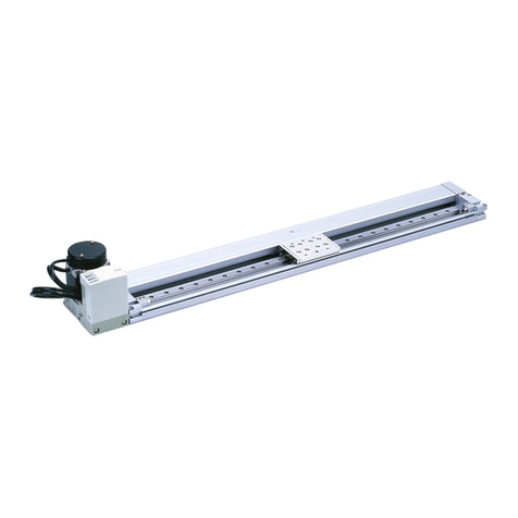
SMC Networks LEF Series User manual

SMC Networks

SMC Networks LEF Series User manual

SMC Networks LEFS 16 Manual

SMC Networks

SMC Networks LEFS 16 Manual

SMC Networks VCHR30 Series Manual

SMC Networks

SMC Networks VCHR30 Series Manual

SMC Networks LEHF32EK2-64-XA147 User manual

SMC Networks

SMC Networks LEHF32EK2-64-XA147 User manual

SMC Networks ITV0000 Series User manual

SMC Networks

SMC Networks ITV0000 Series User manual

SMC Networks ITV0000 Series User manual

SMC Networks

SMC Networks ITV0000 Series User manual

SMC Networks IRV10 User manual

SMC Networks

SMC Networks IRV10 User manual

SMC Networks CRB2BW40 Series User manual

SMC Networks

SMC Networks CRB2BW40 Series User manual

SMC Networks LEL25M User manual

SMC Networks

SMC Networks LEL25M User manual

SMC Networks JXC73 Series Owner's manual

SMC Networks

SMC Networks JXC73 Series Owner's manual

SMC Networks 25A-LEFS Series User manual

SMC Networks

SMC Networks 25A-LEFS Series User manual

SMC Networks VXFC-06D User manual

SMC Networks

SMC Networks VXFC-06D User manual

SMC Networks IR320-A User manual

SMC Networks

SMC Networks IR320-A User manual

SMC Networks ITV 1 Series User manual

SMC Networks

SMC Networks ITV 1 Series User manual

SMC Networks IR2000-A Series User manual

SMC Networks

SMC Networks IR2000-A Series User manual

SMC Networks ITV2000 series Operating instructions

SMC Networks

SMC Networks ITV2000 series Operating instructions

SMC Networks JAS-L Series User manual

SMC Networks

SMC Networks JAS-L Series User manual

SMC Networks CRQ2X User manual

SMC Networks

SMC Networks CRQ2X User manual

SMC Networks LET-X11 Series User manual

SMC Networks

SMC Networks LET-X11 Series User manual

SMC Networks LE Series User manual

SMC Networks

SMC Networks LE Series User manual

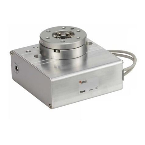
SMC Networks LER Series User manual

SMC Networks

SMC Networks LER Series User manual

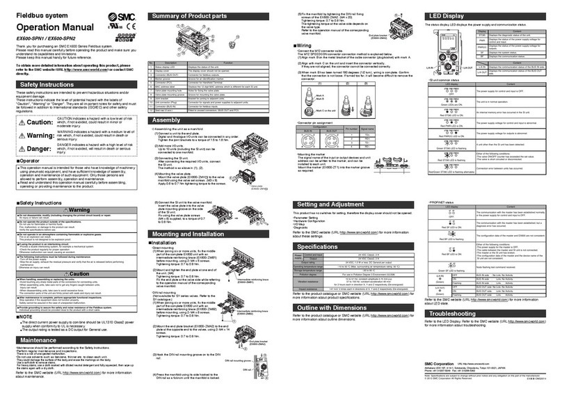
SMC Networks EX600-SPN1 Installation manual

SMC Networks

SMC Networks EX600-SPN1 Installation manual

Popular Controllers manuals by other brands

Festo LF-M Series operating instructions

Festo

Festo LF-M Series operating instructions

Tait T2004 System manual

Tait

Tait T2004 System manual

Napoleon LK48 installation instructions

Napoleon

Napoleon LK48 installation instructions

Rain Bird ESP-RZXe quick start guide

Rain Bird

Rain Bird ESP-RZXe quick start guide

SE Controls OS2 manual

SE Controls

SE Controls OS2 manual

Soyal AR-727HB-RAY Series Installation and programming guide

Soyal

Soyal AR-727HB-RAY Series Installation and programming guide

Prolon C1050 Series Hardware guide

Prolon

Prolon C1050 Series Hardware guide

SOMFY Smoove 1 Tw io installation guide

SOMFY

SOMFY Smoove 1 Tw io installation guide

Unitronics Vision 230 user guide

Unitronics

Unitronics Vision 230 user guide

LG MASTER-K 120S Series user manual

LG

LG MASTER-K 120S Series user manual

DAVIS CT Series manual

DAVIS

DAVIS CT Series manual

Wavelength Electronics WTC3243 manual

Wavelength Electronics

Wavelength Electronics WTC3243 manual

Niko 410-00121 manual

Niko

Niko 410-00121 manual

QuietCool IT-AF-SMT owner's manual

QuietCool

QuietCool IT-AF-SMT owner's manual

Broadcom MegaRAID SAS 9380-8i8e Quick installation guide

Broadcom

Broadcom MegaRAID SAS 9380-8i8e Quick installation guide

Emerson Tartarini M Series instruction manual

Emerson

Emerson Tartarini M Series instruction manual

Chromalox 3340 Setting manual

Chromalox

Chromalox 3340 Setting manual

Metso Neles ValvGuard VG9200H Installation maintenance and operating instructions

Metso

Metso Neles ValvGuard VG9200H Installation maintenance and operating instructions

manuals.online logo
manuals.online logoBrands
  • About & Mission
  • Contact us
  • Privacy Policy
  • Terms and Conditions

Copyright 2025 Manuals.Online. All Rights Reserved.