HP Elite Slice for Meeting Rooms G2 Operating and maintenance manual

Hardware Reference Guide
HP Elite Slice for Meeting Rooms G2

© Copyright 2018 HP Development Company,
L.P.
The information contained herein is subject to
change without notice. The only warranties for
HP products and services are set forth in the
express warranty statements accompanying
such products and services. Nothing herein
should be construed as constituting an
additional warranty. HP shall not be liable for
technical or editorial errors or omissions
contained herein.
Second Edition: March 2018
First Edition: March 2018
Document Part Number: L14947-002
Product Notice
This guide describes features that are common
to most models. Some features may not be
available on your computer.
Software terms
By installing, copying, downloading, or
otherwise using any software product
preinstalled on this computer, you agree to be
bound by the terms of the HP End User License
Agreement (EULA). If you do not accept these
license terms, your sole remedy is to return the
entire unused product (hardware and software)
within 14 days for a refund subject to the
refund policy of your seller.
For any further information or to request a full
refund of the computer, please contact your
local point of sale (the seller).

About This Book
This guide provides basic information for upgrading the HP Elite Slice for Meeting Rooms G2.
WARNING! Indicates a hazardous situation that, if not avoided, could result in death or serious injury.
CAUTION: Indicates a hazardous situation that, if not avoided, could result in minor or moderate injury.
IMPORTANT: Indicates information considered important but not hazard-related (for example, messages
related to property damage). A notice alerts the user that failure to follow a procedure exactly as described
could result in loss of data or in damage to hardware or software. Also contains essential information to
explain a concept or to complete a task.
NOTE: Contains additional information to emphasize or supplement important points of the main text.
TIP: Provides helpful hints for completing a task.
iii

iv About This Book

Table of contents
1 Product features ........................................................................................................................................... 1
HP Elite Slice for Meeting Rooms G2 features ....................................................................................................... 1
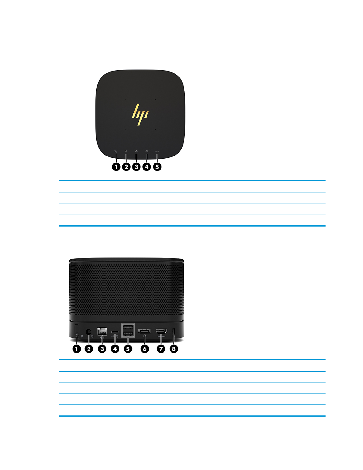
Top components .................................................................................................................................. 2
Rear components ................................................................................................................................ 2
Side components ................................................................................................................................. 3
HP Video Ingest Module ......................................................................................................................................... 3
HP Wireless Display Module (optional) .................................................................................................................. 4
HP Optical Disc Drive (ODD) Module (optional) ...................................................................................................... 5
HP Slice VESA Plate (optional) ............................................................................................................................... 5
Regulatory information and serial number location ............................................................................................ 6
2 Setup ............................................................................................................................................................ 7
Connecting or removing modules .......................................................................................................................... 7
Connecting modules ............................................................................................................................ 7
Connecting modules ......................................................................................................... 7
Connecting the optional Slice VESA Plate ......................................................................... 8
Removing modules ............................................................................................................................ 10
Attaching the Elite Slice G2 to a mounting device ............................................................................................... 11
Installing a security cable .................................................................................................................................... 11
Connecting AC power ........................................................................................................................................... 12
Setting up an Elite Slice G2 conferencing solution ............................................................................................. 13
Microsoft Skype Room System (SRS) conferencing solution ........................................................... 13
Intel Unite conferencing solution ...................................................................................................... 18
3 Hardware upgrades ...................................................................................................................................... 23
Serviceability features ......................................................................................................................................... 23
Warnings and cautions ........................................................................................................................................ 23
Removing and replacing the access panel .......................................................................................................... 24
Removing the access panel ............................................................................................................... 24
Replacing the access panel ............................................................................................................... 25
Locating internal components ............................................................................................................................ 25
v

Upgrading system memory ................................................................................................................................. 26
Memory module specications ......................................................................................................... 26
Populating memory module slots .................................................................................................... 27
Installing system memory modules ................................................................................................. 28
Removing and replacing an SSD .......................................................................................................................... 30
Appendix A Electrostatic discharge .................................................................................................................. 32
Preventing electrostatic damage ........................................................................................................................ 32
Grounding methods ............................................................................................................................................. 32
Appendix B Computer operating guidelines, routine care and shipping preparation ............................................. 33
Computer operating guidelines and routine care ............................................................................................... 33
Shipping preparation ........................................................................................................................................... 34
Appendix C Accessibility ................................................................................................................................. 35
Supported assistive technologies ....................................................................................................................... 35
Contacting support .............................................................................................................................................. 35
Index ............................................................................................................................................................. 36
vi

1 Product features
HP Elite Slice for Meeting Rooms G2 features
The Elite Slice G2 features Bang & Olufsen audio and wireless communication for Intel Unite or Microsoft
Skype Room System (SRS) conferencing software. Four speakers are on the Elite Slice G2, one in each corner
and four microphones are on the top.
HP Elite Slice for Meeting Rooms G2 features 1

Top components
The Elite Slice G2 top components enable call control with capacitive touch buttons for conference calls.
Item Component Item Component
1 Answer/Call 4 Volume up
2 Mute 5 Reject/Disconnect call
3 Volume down
Rear components
Item Component Item Component
1 Power button 5 USB ports (2)
2 Power jack 6 Dual-Mode DisplayPort (D++) port
3 RJ-45 (network) jack 7 HDMI port
4 USB type C port with Alt Mode 8 Security cable slot
2 Chapter 1 Product features

Side components
Item Component Item Component
1 USB Type-C port
(disabled from factory, enabled through system BIOS)
2 Audio-out (headphone)/Audio-in (microphone) combo
jack
HP Video Ingest Module
The Video Ingest Module is required for the Microsoft SRS. This module enables a video source to be
connected to the SRS.
The Video Ingest Module does not support Intel Unite software.
Item Component Item Component
1 Security cable slot 2 HDMI-in port
HP Video Ingest Module 3

HP Wireless Display Module (optional)
The Elite Slice G2 may be ordered with the optional Wireless Display Module. The wireless receiver transceiver
included with the module can be attached to a display. The Wireless Display Module can transmit a signal up
to 10 meters to the transceiver in the room.
TIP: For the best performance, be sure the line of sight between the wireless receiver transceiver and the
Wireless Display Module is optimal.
Item Component Item Component
1 Sync button 3 Security cable slot
2 Sync LED
Item Component Item Component
1 HDMI port 5 VESA plate release button
2 USB Type A power connector 6 VESA plate light
3 Sync LED 7 Wireless receiver transceiver
4 Sync button 8 Wireless receiver transceiver VESA plate
4 Chapter 1 Product features

HP Optical Disc Drive (ODD) Module (optional)
The ODD Module (available as an after-market option) may be ordered to add optical drive functionality.
Additional optical drive modules may be connected to an Elite Slice G2 conguration, depending upon the
power supply and the total number of powered modules.
Item Component Item Component
1 Optical drive disc tray 3 Optical drive eject button
2 Optical drive light 4 Manual eject hole
HP Slice VESA Plate (optional)
The optional Slice VESA Plate enables the Elite Slice G2 assembly to be mounted onto a table. The Elite Slide
G2 should not be mounted to a wall or under a desk.
Item Component Item Component
1 Quick release latch 2 Security cable slot
HP Optical Disc Drive (ODD) Module (optional) 5

Regulatory information and serial number location
Each computer has a unique serial number and a product ID number laser-etched on the base cover of the
Elite Slice G2. A copy of these labels is inside the case. Keep these numbers available for use when contacting
support for assistance.
Item Component Item Component
1 Regulatory label 3 Module connector
2 Regulatory and service information
6 Chapter 1 Product features

2 Setup
Connecting or removing modules
Additional modules may be connected to the Elite Slice G2. Modules should be attached to the base module in
the following order, from top to bottom:
●Video Ingest Module (required for the Microsoft SRS only)
●Wireless Display Module (optional)
●ODD Module (optional)
●VESA Plate (optional)
Connecting modules
Connecting modules
CAUTION: Before connecting modules, turn o the Elite Slice G2 and disconnect it from any AC power
source.
Modules cannot be “hot-plugged” or “hot-swapped.”
1. Remove/disengage the security cable, if one is attached.
2. Remove all removable media, such as USB ash drives.
3. Turn o the Elite Slice G2 properly through the operating system, and then turn o any external devices.
4. Disconnect the AC power cord from the Elite Slice G2 and disconnect any external devices.
5. If the VESA Plate is connected, slide the quick release latch to the unlocked position and remove the
VESA Plate.
Connecting or removing modules 7

6. Align the module connection port on the underside of the Elite Slice G2 with the module expansion
connector on the new module and press the computer down rmly.
You should hear a quiet click when the modules lock together. The module locks into place and hides the
release latch of the module above it.
Repeat until all modules have been connected.
Connecting the optional Slice VESA Plate
If the VESA Plate is connected, the Elite Slice G2 can be mounted onto a table.
CAUTION: Before connecting the VESA Plate, turn o the Elite Slice G2 and disconnect it from any AC power
source.
1. Slide the quick release latch on the VESA Plate to the unlocked position. Position the connected modules
over the VESA Plate.
The VESA Plate does not have a module expansion connector. Be sure that the ports of the Elite Slice G2
and the quick release latch and security cable slot of the VESA Plate are all on the same side.
2. Press the modules down onto the VESA Plate.
8 Chapter 2 Setup

3. Slide the quick release latch on the back of the VESA Plate to the locked position to lock all modules
together.
CAUTION: There are four tabs in the VESA Plate. When you position the Elite Slice G2 conguration
correctly onto the VESA Plate and slide the quick release latch to the locked position, the four tabs lock
the VESA Plate to the Elite Slice G2 assembly. If the VESA Plate is not correctly oriented, the quick
release latch cannot be moved to the locked position and the modules are not secured.
4. Install a security cable in the VESA Plate security cable slot to prevent the quick release latch from being
unlocked and the modules from being separated.
NOTE: The security cable is designed to act as a deterrent, but it may not prevent the computer from
being mishandled or stolen.
Connecting or removing modules 9

Removing modules
CAUTION: Before disconnecting modules, turn o the Elite Slice G2 and disconnect it from any AC power
source.
Modules cannot be “hot-plugged” or “hot-swapped.”
Modules must be removed one at a time, starting at the bottom. Removing the bottom module exposes the
release latch of the module above it.
1. Remove/disengage the security cable, if one is attached.
2. Remove all removable media, such as USB ash drives.
3. Turn o the Elite Slice G2 properly through the operating system, and then turn o any external devices.
4. Disconnect the AC power cord from the Elite Slice G2 and disconnect any external devices.
5. If the VESA Plate is connected, slide the quick release latch on the back of the VESA Plate to the unlocked
position and lift the module stack o the VESA Plate.
6. Beginning at the bottom, remove additional modules by pressing the release latch (1) on the underside
of each module until it releases the module (2) above it.
10 Chapter 2 Setup

Attaching the Elite Slice G2 to a mounting device
If the VESA Plate, available as an option, is connected, the Elite Slice G2 can be attached to a table.
To mount the Elite Slice G2:
1. Connect all modules except the VESA Plate.
2. Use the four screws provided with the VESA Plate to attach the VESA Plate to a table or other surface.
3. Carefully connect the modules to the VESA Plate.
4. Slide the quick release latch on the rear of the VESA Plate to the locked position to secure the VESA Plate
to the module above it.
NOTE: HP highly recommends that you secure the Elite Slice G2 assembly by attaching a security cable
to the rear of the VESA Plate. This stops the quick release latch from being moved to the unlocked
position and prevents accidental release of the modules.
The security cable is designed to act as a deterrent, but it may not prevent the computer from being
mishandled or stolen.
Installing a security cable
The 10 mm ultra-slim cable lock displayed below can be used to secure the computer. When installed in the
bottom module, the cable locks all modules together. If the VESA Plate is installed, slide the quick release to
the locked position and install a security cable to lock all modules together.
Attaching the Elite Slice G2 to a mounting device 11

NOTE: The security cable is designed to act as a deterrent, but it may not prevent the computer from being
mishandled or stolen.
Connecting AC power
The Elite Slice G2 employs the HP Cable and Port Cover to supply power to the elements of the conferencing
solution.
1. Connect the Cable and Port Cover to the Elite Slice G2:
a. Pull the port cover down (1) to expose the cable connectors.
b. Pull the rst and last connectors out (2) to each side.
c. Beginning with the HDMI connector and nishing with the NIC connector, plug all middle connectors
into the rear ports (3) on the Elite Slice G2.
d. Connect side cables (4).
e. Push the port cover back over the cable connectors (5) to protect and secure the connectors.
2. Connect remaining equipment, such as a CoRC or a display, to the Cable and Port Cover.
3. Connect the AC power cord to the power adapter (1) and the other end to an AC outlet (2).
12 Chapter 2 Setup

4. Connect the power supply connector to the power connector on the Cable and Port Cover (3).
Setting up an Elite Slice G2 conferencing solution
The Elite Slice G2 has two conferencing solutions:
●Microsoft Skype Room System (SRS)
●Intel Unite
Microsoft Skype Room System (SRS) conferencing solution
The SRS ships with Microsoft SRS software, HP Elite Slice G2, HP Center of Room Control (CoRC), HP Video
Ingest Module, and HP Cable and Port Cover. The HP Wireless Display Module and HP VESA mount are
optional.
Item Component Item Component
1 HP Elite Slice for Meeting Rooms G2 3 HP Cable and Port Cover
2 HP Center of Room Control (CoRC) 4 HP Video Ingest Module
Setting up an Elite Slice G2 conferencing solution 13

TIP: When routing cables under a table or other surface, cable guides, shown in red above, should be used
to minimize stress on the cables.
1. Connect the Video Ingest Module (required) to the Elite Slice G2.
2. Connect additional modules, if desired, to the Elite Slice G2.
3. Place the Elite Slice G2 in a central location.
Be sure nothing is placed on top of or next to the Elite Slice G2 that could block speakers and
microphones.
4. Connect the Cable and Port Cover to the Elite Slice G2:
a. Pull the port cover down (1) to expose the cable connectors.
b. Pull the rst and last connectors out to each side (2).
c. Beginning with the HDMI connector and nishing with the NIC connector, plug all middle connectors
into the rear ports (3) on the Elite Slice G2.
d. Connect the rst and last connectors (4).
e. Push the port cover back over the cable connectors (5) to protect and secure the connectors.
5. Connect the CoRC.
a. Connect the USB-C cable from the top of the Cable and Port Cover to an exit port on the rear of the
CoRC (1). Press the cable into the channel (2) to exit on either the left or right side of the CoRC.
14 Chapter 2 Setup
Table of contents