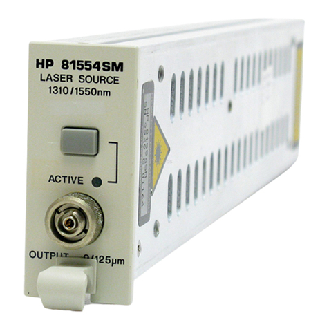
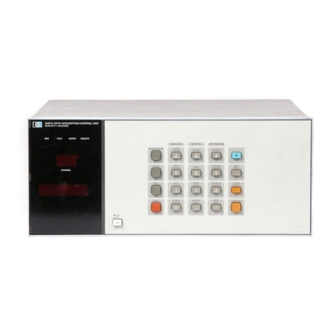
HP 83400 Series User manual

The test & measurement
equipment you need at
the price you want.
Alltest carries the world’s largest selection of
used/refurbished benchtop test & measurement
equipment at 50% the price of new.
O
Our equipment is guaranteed working, warrantied, and
available with certified calibration from our in-house staff
of technicians and engineers.
• 10+ full time technicians with over 150 years of
specialization
• 90 day warranty & 5 day right of return on all
equipment
•
• 1-3 year warranties for new and
premium-refurbished equipment
• Every unit tested to OEM specifications
• Satisfaction guaranteed
You have plans, we will help you achieve them.
Any project. Any budget.
Get a quote today!
CCall (732) 919-3339 or email sales@alltest.net.
t
Alltest Instruments, Inc.
500 Central Ave.
Farmingdale, NJ 07727
P: (732) 919-3339
F: (732) 919-3332
alltest.net
s
sales@alltest.net

User’s Guide
HP 83400-Series Lightwave
Source and Receiver Modules

ii
© Copyright Hewlett-Packard
Company 1999
All Rights Reserved. Repro-
duction, adaptation, or trans-
lation without prior written
permission is prohibited,
except as allowed under copy-
right laws.
HP Part No. 5962-5930
Printed in USA
August 1999
Hewlett-Packard Company
Lightwave Operations
1400 Fountaingrove Parkway
Santa Rosa, CA 95403-1799,
USA
(707) 577-1400
Notice.
The information contained in
this document is subject to
change without notice. Com-
panies, names, and data used
in examples herein are ficti-
tious unless otherwise noted.
Hewlett-Packard makes no
warranty of any kind with
regard to this material, includ-
ing but not limited to, the
implied warranties of mer-
chantability and fitness for a
particular purpose. Hewlett-
Packard shall not be liable for
errors contained herein or for
incidental or consequential
damages in connection with
the furnishing, performance,
or use of this material.
Restricted Rights Legend.
Use, duplication, or disclo-
sure by the U.S. Government
is subject to restrictions as set
forth in subparagraph (c) (1)
(ii) of the Rights in Technical
Data and Computer Software
clause at DFARS 252.227-7013
for DOD agencies, and sub-
paragraphs (c) (1) and (c) (2)
of the Commercial Computer
Software Restricted Rights
clause at FAR 52 .227-19 for
other agencies.
Warranty.
This Hewlett-Packard instru-
ment product is warranted
against defects in material and
workmanship for a period of
one year from date of ship-
ment. During the warranty
period, Hewlett-Packard Com-
pany will, at its option, either
repair or replace products
which prove to be defective.
For warranty service or repair,
this product must be returned
to a service facility desig-
nated by Hewlett-Packard.
Buyer shall prepay shipping
charges to Hewlett-Packard
and Hewlett-Packard shall pay
shippi ng charges to return the
product to Buyer. However,
Buyer shall pay all shipping
charges, duties, and taxes for
products returned to Hewlett-
Packard from another coun-
try.
Hewlett-Packard warrants
that its software and firmware
designated by Hewlett-Pack-
ard for use with an instrument
will execute its programming
instructions when properly
installed on that instrument.
Hewlett-Packard does not
warrant that the operation of
the instrument, or software,
or firmware will be uninter-
rupted or error-free.
Limitation of Warranty.
The foregoing warranty shall
not apply to defects resulting
from improper or inadequate
maintenance by Buyer, Buyer-
supplied software or interfac-
ing, unauthorized modifica-
tion or misuse, operation
outside of the environmental
specifications for the product,
or improper site preparation
or maintenance.
No other warranty is
expressed or implied.
Hewlett-Packard specifically
disclaims the implied warran-
ties of merchantability and fit-
ness for a particular purpose.
Exclusive Remedies.
The remedies provided herein
are buyer's sole and exclusive
remedies. Hewlett-Packard
shall not be liable for any
direct, indirect, special, inci-
dental, or consequential dam-
ages, whether based on
contract, tort, or any other
legal theory.
Safety Symbols.
CAUTION
The caution si gn denotes a
hazard. It calls attention to a
procedure which, if not cor-
rectly performed or adhered
to, could result in damage to
or destruction of the product.
Do not proceed beyond a cau-
tion sign until the indicated
conditions are fully under-
stood and met.
WA R N I N G
The warning sign denotes a
hazard. It calls attention to a
procedure which, if not cor-
rectly performed or adhered
to, could result in injury or
loss of life. Do not proceed
beyond a warning sign until
the indicated conditions are
fully understood and met.
The instruction man-
ual symbol. The prod-
uct is marked with this
warning symbol when
it is necessary for the
user to refer to the
instructions in the
manual.
The laser radiation
symbol. This warning
symbol is marked on
products which have a
laser output.
The AC symbol is used
to indicate the
required nature of the
line module input
power.
|The ON symbols are
used to mark the posi-
tions of the instrument
power line switch.
❍The OFF symbols
are used to mark the
positions of the instru-
ment power line
switch.
The CE mark is a reg-
ister ed trademark of
the European Commu-
nity.
The CSA mark is a reg-
ister ed trademark of
the Canadian Stan-
dards Association.
The C-Tick mark is a
registered trademark
of the Australian Spec-
trum Management
Agency.
This text denotes the
instrument is an
Industrial Scientific
and Medical Group 1
Class A product.
ISM1-A

iii
The HP 83400-Series—At a Glance
HP 83400-series sources
The HP 83400-series sources can be amplitude modulated by an external RF
source. They can be modulated with up to +14 dBm (about 25 mW) of RF
power.
WARNING Use of controls or adjustments or performance of procedures other
than those specified herein can result in hazardous radiation
exposure.
WARNING Do not enable the laser when no fiber or equivalent device is attached
to the OPTICAL OUTPUT connector.
HP 83400-series receivers
The receivers are used to demodulate lightwave signals. With no modulation
signal, lightwave receivers produce no electrical output. If the optical power
exceeds 3 mW, the front-panel OVER ILLUMINATION indicator lights. Power must
be decreased below 2.5 mW for the indicator to turn off.
Source Wavelength Unmodulated
Output Power
Modulation
Range
Optical
Fiber
Laser
Type
HP 83402C 1300 nm < 3.0 mW 300 kHz to 6 GHz 9/125 µmDFB
HP 83403C 1550 nm < 3.0 mW 300 kHz to 6 GHz 9/125 µmDFB
Receiver Wavelength Demodulation Range
(sine wave) Optical Fiber
HP 83410C 1300/1550 nm 300 kHz to 3 GHz 62.5/125 µm
HP 83411C/D 1300/1550 nm 300 kHz to 6 GHz 9/125 µm
HP 83412B 850 nm 300 kHz to 3 GHz 62.5/125 µm

iv
Laser classification
The HP 83402C is classified as an FDA LASER Class IIIb (IEC LASER Class
3B). The total power of light energy radiated out of the OPTICAL OUTPUT con-
nector is no greater than 5 mW at a wavelength of 1300 nm. The following fig-
ure shows the IEC and FDA labels (and thier placement) on the HP 83402C.
The HP 83403C is classified as an FDA LASER Class I (IEC LASER Class 1).
The total power of light energy radiated out of the OPTICAL OUTPUT connector is
no greater than 5 mW at a wavelength of 1550 nm.
No adjustments or maintenance are required to keep these products compli-
ant with their classification. The IEC labels shown in the figure could not be
affixed at the factory. Instructions on page 1-5 explain how they are to be
attached.
WARNING Do NOT, under any circumstances, look into the optical output or any
fiber/device attached to the output while the laser is in operation.
WARNING Do not enable the laser when no fiber or equivalent device is attached
to the OPTICAL OUTPUT connector.
These products cannot be serviced. If service is required, return the instru-
ment to HP.

v
Laser classification
IEC and FDA labels (and thier placement) on an HP 83402C

vi
General Safety Considerations
This product has been designed and tested in accordance with IEC Publica-
tion 1010, Safety Requirements for Electronic Measuring apparatus, and has
been supplied in a safe condition. The instruction documentation contains
information and warnings which must be followed by the user to ensure safe
operation and to maintain the product in a safe condition.
WARNING If this product is not used as specified, the protection provided by the
equipment can be impaired. This product must be used in a normal
condition (in which all means for protection are intact) only.
WARNING For any repairs, always return the product to the factory. Always refer
servicing to qualified HP personnel. No operator serviceable parts
inside. To prevent electrical shock, do not remove covers.

Contents
Contents-1
The HP 83400-Series—At a Glance iii
Laser classification iv
General Safety Considerations vi
1 Getting Started
Inspecting the Shipment 1-4
Connecting a Source 1-5
Connecting a Receiver 1-8
Entering Calibration Data into an HP 8702D 1-9
Entering Calibration Data into an HP 8702A/B 1-11
2 General Information
Operating 2-2
Replaceable Parts 2-5
Calibration Data Information 2-7
Cleaning Connections for Accurate Measurements 2-10
Theory of Operation 2-16
Returning the Instrument for Service 2-20
Hewlett-Packard Sales and Service Offices 2-23
3 Specifications and Regulatory Information
Specifications for Sources 3-3
Specifications for Receivers 3-7
Operating Specifications for Sources and Receivers 3-14
Regulatory Information 3-15
4 Performance Tests
Tests for Sources 4-4
Tests f o r Rec eiv ers 4 -7

Contents-2
Contents

1
Inspecting the Shipment 1-4
Connecting a Source 1-5
If you encounter a problem 1-7
Connecting a Receiver 1-8
Entering Calibration Data into an HP 8702D 1-9
To copy the data from the disk 1-10
To manually enter data from the label 1-10
Entering Calibration Data into an HP 8702A/B 1-11
To install from the front panel 1-11
To install from an external disk drive 1-12
Getting Started

1-2
Getting Started
Getting Started
Getting Started
The instructions in this chapter show you how to install your HP 83400-series
source or receiver module. Because these products are key accessories for the
HP 8702-series lightwave component analyzers, this book emphasizes installa-
tion into the HP 8702D.
Calibration data describes each device
Four procedures are provided in this chapter for loading source or receiver
calibration data into an HP 8702-series lightwave component analyzer. Select
the appropriate procedure depending upon your situation.
Each source and receiver module comes with its own calibration data that
describes its magnitude and phase modulation response. Because no two
sources or receivers are exactly alike, the calibration data should not be used
with any other source or receiver. The calibration data is provided in three
forms:
•Coefficients printed on a label.
•Data on a DOS-formatted disk.
•Data on a LIF-formatted disk.
For more information about the calibration data, refer to “Calibration Data In-
formation”on page 2-7.
Some notes on safety and care
Be sure to read the safety and introductory material in the front of this book
before operating your HP 83400-series source or receiver module. Refer to
Chapter 3, “Specifications and Regulatory Information”for information on
operating conditions, such as temperature.
If you should ever need to clean the cabinet, use a damp cloth only.
CAUTION Exposing the HP 83400-series source or receiver module to temperatures
above 55°C may cause the optical fiber in the front-panel connector to shrink
and retract.

1-3
Getting Started
Getting Started
CAUTION This product is designed for use in INSTALLATION CATEGORY II and
POLLUTION DEGREE 2, per IEC 601010 and 60664 respectively.
Measurement accuracy—it’s up to you!
Fiber-optic connectors are easily damaged when connected to dirty or damaged cables
and accessories. The HP 83400-series’s front-panel optical connector is no exception.
When you use improper cleaning and handling techniques, you risk expensive instru-
ment repairs, damaged cables, and compromised measurements.
Before you connect any fiber-optic cable to the HP 83400-series source or receiver mod-
ule, refer to “Cleaning Connections for Accurate Measurements” on page 2-10.

1-4
Getting Started
Inspecting the Shipment
1Verify that all components ordered have arrived by comparing the shipping
forms to the original purchase order. Inspect all shipping containers.
If your shipment is damaged or incomplete, save the packing materials and
notify both the shipping carrier and the nearest Hewlett-Packard sales and
service office. HP will arrange for repair or replacement of damaged or incom-
plete shipments without waiting for a settlement from the transportation com-
pany. Notify the HP customer engineer of any problems.
2Make sure that the serial number and options listed on the instrument’s rear-
panel label match the serial number and options listed on the shipping
document. The following figure is an example of the rear-panel serial number
label.
Figure 1-1. Serial number label

1-5
Getting Started
Connecting a Source
Connecting a Source
1For HP 83402C products, perform the following two steps:
aIf you are located outside of the United States or Canada, locate the yellow
sheet of IEC laser classification and laser safety labels supplied with the
source. Labels are provided for most major languages.
bSelect the two labels in the desired language, and place them on the source
at the two positions shown in Figure 1-2 on page 1-6. FDA labels should al-
ready be located at these positions.
WARNING Do NOT, under any circumstances, look into the optical output or any
fiber/device attached to the output while the laser is in operation.
2Connect a terminated fiber-optic cable or device to the source’s OPTICAL OUTPUT
connector. This protects the user from exposure to laser radiation. See Figure
1-3 on page 1-7.
3Connect the DC cable, supplied with the source, between the source’s rear-
panel DC IN connector and a PROBE POWER jack.
Yo u’ll find PROBE POWER jacks on the following products:
•HP 8702A/B/D lightwave component analyzer
•HP 11899A probe power supply
4Make sure that the BNC short is connect to the rear-panel REMOTE SHUTDOWN
connector.
The source will not operate without the BNC short connected.
5Insert the key into the source’s front panel.
6Turn the key to turn the source on.

1-6
Getting Started
Connecting a Source
Figure 1-2. Location of laser safety labels

1-7
Getting Started
Connecting a Source
Figure 1-3. Source connections
If you encounter a problem
If the TEMP LED comes on, or the LASER ON LED goes off, one or more of the fol-
lowing conditions may have occurred:
•The key switch is in the OFF position (O).
•The ambient temperature is out of the specified range (25°C ±5°C).
•The remote shutdown is open.
•The power supply voltage(s) are out of spec (–12.6 V ±5% and +15 V ±5%).
•There is an internal malfunction of the unit; contact Hewlett-Packard for assis-
tance.
These products cannot be serviced. If service is required, return the instru-
ment to HP.

1-8
Getting Started
Connecting a Receiver
1Connect the DC cable, supplied with the receiver, between the receiver’s rear-
panel DC IN connector and a PROBE POWER jack.
Yo u’ll find PROBE POWER jacks on the following products:
•HP 8702A/B/D lightwave component analyzer
•HP 11899A probe power supply
2Locate the SMA RF cable supplied with the receiver.
3Use adapters to connect the SMA RF cable between the HP 8702’s RF port and
the receiver’s rear-panel RF OUT connector.
4Connect a fiber-optic cable or device to the receiver’s OPTICAL INPUT connector.

1-9
Getting Started
Entering Calibration Data into an HP 8702D
HP 83400-series lightwave sources and receivers have calibration data which
must be entered into the HP 8702. The data is supplied on a disk and printed
on a label. The most accurate data is contained on the disk. The calibration
data for newer lightwave sources and receivers is supplied on a DOS format-
ted disk which can be read using the front-panel disk drive. On older sources
and receivers, the disk uses the LIF format.
Calibration standards come in the following forms:
•Already loaded in the HP 8702’s memory.
For optical transmission measurements, a thru connection (short length of
fiber-optic cable) is used. For reflection measurements, a Fresnel reflection
(3.5% reflected power) is used. This is a clean connector on the output of a
lightwave coupler. For electrical measurements, standard devices include
short circuit, open circuit, termination (for example, 50Ωload), and thru
connection. Electrical standards are packaged together as calibration kits.
•Provided with the device and must be loaded into the HP 8702’s memory.
For example, the HP 83400-series lightwave sources and receivers are
shipped with calibration data stored on a disk. This disk must be placed into
the instrument’s front-panel disk drive so that the data can be loaded into
memory.
•Calibration standards that you create for your own devices.
Loading calibration data into an HP 8702D
Before using your source or receiver with an HP 8702D lightwave component
analyzer, you must load the calibration data as described in this section. Two
simple procedures are provided in this section. Although both are easy to per-
form, copying from a disk is slightly faster. The data on the disk provides the
most accurate model of the frequency response of the calibration standard. As
an alternative, entering the coefficients that are printed on the label (located
on the source or receiver) provides lower accuracy.
For steps on entering calibration data into an HP 8702A/B, refer to “Entering
Calibration Data into an HP 8702A/B”on page 1-11.

1-10
Getting Started
Entering Calibration Data into an HP 8702D
To copy the data from the disk
The following procedure is written specifically for entering source data. If you
are entering data for a receiver, simply substitute the word RECEIVER for SOURCE
and the word RCVR for SRC.
1Locate the DOS-formatted calibration disk provided with the source.
2Place the disk in the HP 8702D’s front-panel disk drive.
3Press CAL, CAL KITS & STDS, SOURCE STANDARDS, LOAD SRC DISK MENU. This will
display the disk directory screen.
4Use the arrow keys or front panel knob to select a cal data file.
5Load the cal data file into either of two internal registers by pressing the
corresponding LOAD softkey.
To manually enter data from the label
The following procedure is written specifically for entering source data. If you
are entering data for a receiver, simply substitute the word RECEIVER for SOURCE
and the word RCVR for SRC.
1Press CAL, CAL KITS & STDS, SOURCE, CAL STD:SRC COEFF and then ENTER SRC COEFF.
2Press each softkey corresponding to the nine coefficients (A through I), using
the MORE softkey, and enter the coefficients. The coefficients are listed on a
label that is on the source. After all of the coefficients are entered, press
RETURN.
3Press LABEL STD.
4Use the front-panel knob and the SELECT LETTER softkey to write a title for the
calibration data.
5Press STD DONE (DEFINED) and then SAVE SRC COEFF.
6Press CAL, CALIBRATE MENU, RESPONSE, and then SOURCE.
7When the SOURCE softkey is underlined, press DONE: RESPONSE.

1-11
Getting Started
Entering Calibration Data into an HP 8702A/B
Before using your source or receiver with an HP 8702A/B lightwave compo-
nent analyzer, you must load the calibration data as described in this section.
Two procedures are provided in this section. The first procedure is the stan-
dard method. You will most likely use it. However, if you have an HP-IB exter-
nal disk drive, you can use the second procedure. For more information on
calibration data, refer to “Entering Calibration Data into an HP 8702D”on
page 1-9.
To install from the front panel
The following procedure is written specifically for entering source data. If you
are entering data for a receiver, simply substitute the word RECEIVER for SOURCE
and the word RCVR for SRC.
1On the HP 8702A/B, press:
PRESET
CAL, CAL KITS & STDS, SOURCE [COEFF], SRC COEFF, ENTER SRC COEFF
2Use the available softkeys to enter the coefficients that are listed on the label
that is attached to the source.
3Press LABEL STD, and enter a label for the calibration data.
4Press STD DONE and then SAVE SRC COEFF.
This manual suits for next models
2
Table of contents
Other HP Control Unit manuals
Popular Control Unit manuals by other brands

RTA
RTA X-PLUS C Series instruction manual

Watts
Watts LF25AUB-Z3 Series Installation instructions and instructions for use

FLOWROX
FLOWROX SKF DN700 Installation, operation and maintenance instructions

American Standard
American Standard R127 installation instructions

DR. Z Amplification
DR. Z Amplification Brake Lite manual

herdstar
herdstar BinTrac DBTB-200 installation manual