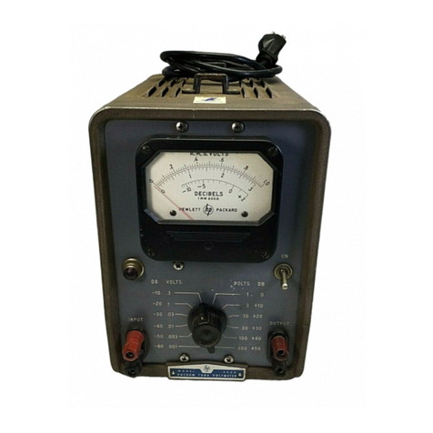
HP 3455A Service manual

chp
34554
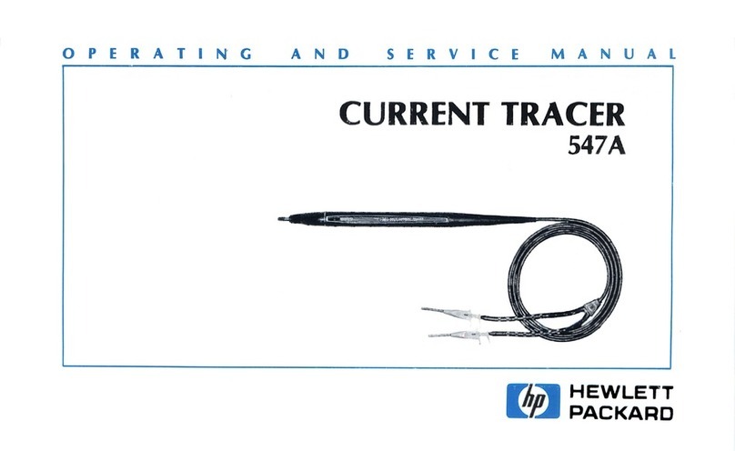
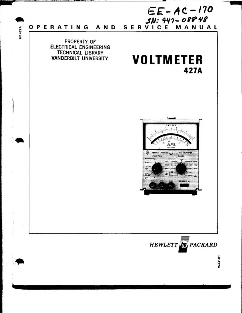
OPERATING
AND
SERVICE
MANUAL
DIGITAL
VOLTMETER
3455A
|G
HEWLETT
PACKARD
wosve
dq:

Revised
Date:
March
1982
{i
HEWLETT
PACKARD
OPERATING
AND
SERVICE
MANUAL
MODEL
3455A
DIGITAL
VOLTMETER
Serial
Numbers:
1622A00101
and
Greater
IMPORTANT
NOTICE
This
loose
leaf
manual
does
not
normally
require
a
change
sheet.
All
major
change
information
has
been
integrated
into
the
manual
by
page
revision.
In
cases
where
only
minor
changes
are
required,
a
change
sheet
may
be
supplied.
If
the
Serial
Number
of
your
instrument
is
lower
than
the
one
on
this
title
page,
the
manual
contains
revisions
that
do
not
apply
to
your
instrument.
Backdating
information
given
in
the
manual
adapts
it
to
earlier
instruments.
Where
practical,
backdating
information
is
integrated
into
the
text,
parts
list
and
schematic
diagrams.
Backdating
changes
are
denoted
by
a
delta
sign.
An
open
delta
(A)
or
lettered
delta
(Aq)
on
a
given
page,
refers
to
the
corresponding
backdating
note
on
that
page.
Backdating
changes
not
integrated
into
the
manual
are
denoted
by
a
numbered
delta
(A
1)
which
refers
to
the
correspond-
.
ing
change
in
the
Backdating
section
(Section
VII).
To
help
minimize
the
possibility
of
electrical
fire
or
shock
hazards,
do
not
expose
this
instrument
to
rain
or
excessive
moisture.
Manual
Part
No.
03455-90003
Microfiche
Part
No.
03455-90053
Revision
A
©Copyright
Hewlett-Packard
Company
1976
P.O.
Box
301,
Loveland,
Colorado,
80537
U.S.A.
Printed:
July
1979

(@))|
Backann
CERTIFICATION
Hewlett-Packard
Company
certifies
that
this
product
met
its
published
specifications
at
the
time
of
shipment
from
the
factory,
Hewlett-Packard
further
certifies
that
its
calibration
measurements
are
traceable
to
the
United
States
Na-
tional
Bureau
of
Standards,
to
the
extent
allowed
by
the
Bureau’s
calibration
facility,
and
to
the
calibration
facilities
of
other
International
Standards
Organization
members.
WARRANTY
This
Hewlett-Packard
product
is
warranted
against
defects
in
material
and
workmanship
for
a
period
of
one
year
from
date
of
shipment
{,except
that
in
the
case
of
certain
components
listed
in
Section
I
of
this
manual,
the
warranty
shall
be
for
the
specified
period)
.
During
the
warranty
period,
Hewlett-Packard
Company
will,
at
its
option,
either
repair
or
replace
products
which
prove
to
be
defective.
For
warranty
service
or
repair,
this
product
must
be
returned
to
a
service
facility
designated
by
-hp-.
Buyer
shall
prepay
shipping
charges
to
-hp-
and
-hp-
shall
pay
shipping
charges
to
return
the
product
to
Buyer.
However,
Buyer
shall
pay
all
shipping
charges,
duties,
and
taxes
for
products
returned
to
-hp-
from
another
country.
Hewlett-Packard
warrants
that
its
software
and
firmware
designated
by
-hp-
for
use
with
an
instrument
will
execute
its
programming
instructions
when
properly
installed
on
that
instrument.
Hewlett-Packard
does
not
warrant
that
the
operation
of
the
instrument,
or
software,
or
firmware
will
be
uninterrupted
or
error
free.
LIMITATION
OF
WARRANTY
The
foregoing
warranty
shall
not
apply
to
defects
resulting
from
improper
or
inadequate
maintenance
by
Buyer,
Buyer-supplied
software
or
interfacing,
unauthorized
modification
or
misuse,
operation
outside
of
the
environmental
specifications
for
the
product,
or
improper
site
preparation
or
maintenance.
.NO
OTHER
WARRANTY
IS
EXPRESSED
OR
IMPLIED.
HEWLETT-PACKARD
SPECIFICALLY
DISCLAIMS
THE
IMPLIED
WARRANTIES
OF
MERCHANTABILITY
AND
FITNESS
FOR
A
PARTICULAR
PURPOSE.
EXCLUSIVE
REMEDIES
THE
REMEDIES
PROVIDED
HEREIN
ARE
BUYER’S
SOLE
AND
EXCLUSIVE
REMEDIES.
HEWLETT-
PACKARD
SHALL
NOT
BE
LIABLE
FOR
ANY
DIRECT,
INDIRECT,
SPECIAL,
INCIDENTAL,
OR
CONSE-
QUENTIAL
DAMAGES,
WHETHER
BASED
ON
CONTRACT,
TORT,
OR
ANY
OTHER
LEGAL
THEORY.
ASSISTANCE
Product
maintenance
agreements
and
other
customer
assistance
agreements
are
available
for
Hewlett-Packard
products.
For
any
assistance,
contact
your
nearest
Hewlett-Packard
Sales
and
Service
Office.
Addresses
are
provided
at
the
back
of
this
manual.
10/1/79

oS
@
@
Model
3455A
TABLE
OF
CONTENTS
Section
Page
I.
GENERAL
INFORMATION.............-
1-1
I-1,
Introduction
..............
ccc
eee
eee
1-1
1-5.
Specifications
................-.00005
1-1
1-7,
Instrument
and
Manual
{dentification.
..
1-1
1-11.
Description
1
1-13.
Options
...........
000s
]
1-15.
Accessories
Supplied
1
1-17.
Accessories
Available...
1
1-19.
Recommended
Test
Equipment.......
1-2
1-21.
Safety
Considerations...............
1-2
Section
Page
Il.
INSTALLATION
.......2............005.
2-1
2-1,
Introduction
.......
0.
cece
cece
eee
2-1
2-3.
Initial
Inspection...................-.
2-1
2-5.
Preparation
for
Use................0.
2-1
2-6.
Power
Requirements................
2-1
2-8.
Line
Voltage
Selection...............
2-1
2-10.
Power
Cable........2.......2...000.
2-1
2-12.
Grounding
Requirements............
2-1
274.
-
Berich®
Us@
ise
uccap.
dia
ster
stk
gatos
tals
sie
ee
2-1
2-16.
Rack
Mounting....................0.
2-2
2-18.
Interface
Connections...............
2-2
2-22,
Environmental
Requirements..........
2-2
2-23.
Operating
and
Storage
Temperature.
..2-3
2-26.
Humidity...................
202
eee
2-3
2-283)
-AlUtUde®...
os.
gas
Gln
e
Cee
id
ch
whe
by
2-3
2-30.
Repackaging
for
Shipment............
2-3
Section
Page
IH)
OPERATING
INSTRUCTIONS.
...........
3-1
3-1.
Introduction
..............2...-.00.-
3-1
3-3.
Operating
Characteristics.............
3-1
3-4.
Turn-On
and
Warm-Up..............
3-1
3-6.
Self-Test
Operation.................
3-1
3-10.
DC
Voltage
Measurement............
3-1
3-12.
Resistance
Measurement.............
3-2
3-14.
AC
Voltage
Measurement............
3-2
3-19.
Math
Feature.......................
3-3
3-23.
Enter
and
Store..............2.-0005
3-4
3-27.
High
Resolution
Mode...............
3-4
3-29)»
AUtO-Cal
i
invitee
Seiantoie
acters
3-5
3533.
Triseeres:is
ale
eeu
sewaharntedeteecs
de
3-5
3-36.
Sample
Rate....................04.
3-5
3-38.
Auto
Range...............
0c
cece
3-6
3-41.
Guarding
................222..00000-
3-6
3-42.
Common-Mode
Voltages.............
3-6
3-44.
Guard
Connection..................
3-6
3-46.
Guarding
Information.............-.
3-6
_
3-48.
Remote
Operation................04.
3-7
349s
General
Suis
sso
da
sk
teed,
chin
Ravine
dee
8G
3-7
3-53.
Address
Selection.................6-
3-7
3-56.
Program
Codes...................--
3-8
3-61.
Data
Messages...................00.
3-9
3-69.
Device
Control
Messages............
3-12
3-78.
Interrupt
and
Device
Status
Messages
0.5.
c0-05.
00s
See
tease
3-12
Section
Table
of
Contents
Page
Ill.
OPERATING
INSTRUCTIONS
(Cont'd)
3-82,
Data
Output
Characteristic
3-84.
Bail
Out
Message..................
3-86.
Instrument
Measurement
Times
(Remote
Control)..............05-
3-13
3-88.
Remote
Programming
Examples.....
3-14
3-90.
Operators
Checks..........cee
eee
ee
3-14
3292:
Bench
Use
ii
:cc:i
deeuheitiea
get
Phe
a
3-14
3-94.
HP-IB
Operation..................
3-14
Section
Page
IV.
PERFORMANCE
TESTS...............--
4-1
4-1.
Introduction
...................-0005
4-1
4-3,
Equipment
Required.................
4-1
4-5.
Performance
Test
Card...............
4-1
4-7.
Calibration
Cycle
4-9.
Input
Terminals/Control
Settings......
4-1
4-11.
Performance
Test
Failure.............
4-1
4-13.
Specification
Breakdown..............
4-1
4-17.
DC
Accuracy
Test
Considerations......
4-2
4-26.
Operational
Verification
Tests.........
4-3
4-27.
DC
Operational
Accuracy
Test.........
4-3
4-30,
Test
Procedure.........
cc
cece
eee
4-3
4-31.
AC
Operational
Accuracy
Test.
.
4-5
4-34.
Test
Procedure...............
ee
teA$
4-35.
Ohmmeter
Accuracy
Test............
4-8
4-37.
Test
Procedure...................0.
4-8
4-38.
DC
Voltmeter
Input
Resistance
Test...
.4-9
4-39.
Performance
Test............ccc
eens
4-9
4-40.
DC
Voltmeter
Accuracy
Test..........
49
4-43.
Test
Procedure................208
4-10
4-44.
AC
Voltmeter
Accuracy
Test........
4-12
4-47.
Test
Procedure....................
4-12
4-48.
Ohmmeter
Accuracy
Test...........
4-16
4-50.
Test
Procedure..............-..008
4-16
4-51.
Common-Mode
and
Normal-Mode
Rejection:
Test:..0<.s220
5
edsshaas
4-17
4-54.
Test
Procedure..............
00.
eee
4-17
4-55.
DC
Voltmeter
Input
Resistance
EOS
bes
sdteieie
y's
cancsee
eid
tis
Reota'g
Musee
eS
4-18
4-56.
AC
Voltmeter
Input
Impedance
TR
OStvis
ions
roca
keine
else
Mtn
Reo
a
©
4-19
Section
V.
ADJUSTMENTS........
2c
cece
cece
eee
5-1.
Introductions,
0.600
ence
der
ces
at
dee
5-3.
Equipment
Required
1
5-5.
Adjustment
Interval.........
1
5-7.
Adjustment
Sequence
5-1
5-9.
Test
Point
and
Adjustment
Locations.
.
.5-1
5-11.
DC
Zero
Adjustments................
5-1
5-12.
DC
and
Ohms
Reference
Adjustments.
. .
5-2
$-14.
Adjustment
Procedure...............
5-2
5-15.
RMS
Convertor
Adjustments
(Standard
Model
3455A
Only).......
5-3
5-16.
Average
Convertor
Adjustments
(3455A
Option
001
Only)............
5-4
5-18.
Adjustment
Procedure...............
5-4
Table
of
Contents
Model
3455A
TABLE
OF
CONTENTS
(Cont'd)
Section
Page
VI.
REPLACEABLE
PARTS................-
6-1
6-1.
Introduction
....................000-
6-1
6-4,
Ordering
Information................
6-1
6-6.
Non-Listed
Parts.............eeen
eee
6-1
6-8.
Parts
Changes............ceceeeeeaee
6-1
6-10.
Proprietary
Parts..................--
6-1
6-12.
Exchange
Assemblies.................
6-2
6-15.
Service
Kit.
....-..c
cece
cece
een
eees
6-2
Section
Page
VII.
MANUAL
CHANGES............0500005-
7-1
F-1.
Introduction.
.............
cece
n
eae
7-1
Section
Page
VIII
SERVICE
64
csc.
ccc
ec
ce
k
ease
bia
sees
8-1
8-1
Introduction...........--...
..
8-!
8-3.
Safety
Considerations...............+--
8-8.
Recommended
Test
Equipment.......
8-1
8-10.
Introduction..............++----0-+
8-2
8-12.
Input
Switching
and
DC
Attenuator.
.
.8-2
8-13.
General.
0...
ccc
cece
eens
8-2
8-15.
Detailed
Description..............-
8-2
8-17.
Operational
Attenuator...........--
8-2
8-19.
Auto
Calibration-DC
Voltage......-..
8-2
8-20,
General
.............
0.
eee
eee
eee
8-2
8-22.
Circuit
Description...............--
8-4
8-34.
Auto-Calibration-Ohms
........-...-
8-9
8-35.
General...
0.2.
eee
ee
ee
eee
eee
8-9
8-37.
Circuit
Description.............----
8-9
8-42.
Auto
Calibration-A/D
Convertor.
...8-10
8-44.
Circuit
Description................
8-11
8-47.
True
RMS
AC
Convertor.........--
8-11
8-48.
General.........
0...
cee
eee
eee
eee
8-11
8-50.
Circuit
Description.........-...+-
8-11
8-56.
Average
Responding
AC
Convertor
(Option
001)...........+-.2000--
8-12
8=87..
General
ji
e.cs
cies
Beebe
cies
deen
se
8-12
8-59.
Circuit
Description.............-++
8-12
8-65.
Ohms
Convertor
8-66.
General
........
0c
cece
eee
eee
8-68.
General
Description...............
8-13
8-73.
DC
Preamplifier..............-00--
8-74.
General
0.0...
eee
eee
ee
eee
8-76.
Circuit
Description
8-82.
Reference
Assembly
8-83.
General
...........--0000
8-85.
Circuit
Description
8-87.
Analog-to-Digital
Convertor
(A/D).
.8-16
8-88.
General
........-.
02
eee
rere
eee
8-16
8-92.
Circuit
Description.
8-103.
Inguard
Controller.
.
8-104.
General
.........
0.00.
ee
eee
eee
ee
8-107.
Circuit
Description............-...
8-115.
Main
Controller..............---5-
8-116.
General
0.0.0...
0.
2c
ee
eee
eee
8-118.
Circuit
Description....
8-141.
HP-IB
Circuit.........
8-142.
General
........
0.0. cece
eee
ctnee
8-144.
Circuit
Description................
8-168.
Front
Panel
Operation..............
8-169.
Circuit
Description................
TROUBLESHOOTING
8-174.
Introduction
.............
cee
neers
8-35
8-176.
General
Block
Diagram
Theory
of
Operation.
..........
06...
e
ee
8
8-179.
Outguard
Section...
8-185,
Inguard
Section....
8-194.
Preliminary
Troubleshooting
Check.
.8-36
8-195.
Instrument
Half-Splitting
Techniques
.....
0.0...
scene
eee
8-36
8-198.
Service
Group
Summary...........
8-37
SERVICE
GROUP
A
8-A-1
Turn-On
Circuitry
(Inguard
and
Outguard).........
0-2.
cece
eee
ee
eee
8-40
8-A-3.
Inguard/Outguard
Isolation...........
8-40
8-A-5.
Outguard
Troubleshooting
(Schematic
8).......
0...
cece
eee
eee
8-40
8-A-6.
Inguard
Troubleshooting
(Schematic
5,
6,
7).........-0see
eens
8-40
8-A-8.
Al0
Motherboard
Troubleshooting
(Schematic
5,
6,
7).........---200045-
8-40
8-A-10.
A/D
Board
Troubleshooting
(Schematic
5,
6).
0.0.2.2...
0c
eee
eee
8-41
8-A-12.
Inguard/Outguard
Transfer
Circuit
Troubleshooting
(Schematic
7,8).
......
8-41
SERVICE
GROUP
B
8-B-1.
Auto-Cal
and
DC
Troubleshooting
(Inguard)
oi:
iscasies
cteigeais
ele
sera
8-43
8-B-3.
Auto-Cal
Constants............--.5--
8-43
8-B-9.
Auto-Cal
Switch
Closures
(Schematic
1,
5, 6,
7)........0cee
eee
8-B-11.
Cal
Constants
Service
Procedure
8-B-14.
Switch
Closure
Table...............55
8-B-16.
Auto-Cal
Troubleshooting
(Schematic
1,
7)....--..
6
eee
eeeereeee
8-52
8-B-18.
DC
Inoperative
(Schematic
1)..........
8-54
8-B-20.
Leakage
and
Other
Various
Malfunctions
..........6+eeeeeeee
eee
8-54
8-B-23.
10
V
Range
or
Constant
10
and
11
Fail.
.
.8-55
8-B-24.
1
V
Range
or
Constant
0,
1,
and
2
Fails.
.8-55
8-B-25.
100mV
Range
or
Constant
3
Fails.......
8-55
8-B-26.
100
V
Range
or
Constants
5,
4,
and
7
Fai
occ
essujaaia
diesartare
isd
ern
aun
as
8-55
8-B-27.
1000
V
Range
or
Constant
6
Fails.......
8-56
8-B-28.
Various
Other
Malfunctions
8-B-30.
Other
Troubleshooting
Hints.
.
8-B-31.
General
Noise.
.......-.00ee
eee
teen
ee
8-B-33.
DC
Noise
(Schematic
1,
5,
and
6).......
8-57

Model
34554
8-C-1.
8-C-2.
8-C-4.
8-C-6.
8-C-8.
8-C-10.
8-C-12.
8-C-16.
8-C-17,
ss
s
Oo
tee
a
oe
Go ld
eee
AWswnrnewn—
b
+
Table
of
Contents
TABLE
OF
CONTENTS
(Cont'd)
SERVICE
GROUP
C
AC
Convertor
Troubleshooting..........
8-59
True
RMS
Convertor
Servicing
(Schematic
3).......
0...
cece
eee
eee
8-59
Preamplifier
and
Input
Alternator
Circuitry...
cicaceavde
eee
eee
ne
on
8-60
Absolute
Amplifier
Circuitry...........
8-61
Squaring
Amplifier,
Intergrator,
and
Antilog
Circuitry....................
AC/DC
Operation...........
AC
Noise
(Schematic
3)
Miscellaneous
Troubleshooting
(Schematic
3)..............
00.0000
8-63
Average
Responding
AC
Convertor
(Schematic
2).................0.0..00.
8-64
SERVICE
GROUP
D
Ohm
Troubleshooting
(Schematic
1,
4)...8-65
Ohms
Circuit
Isolation................
8-65
Ohms
Servicing...............2.00065
8-65
Ohms
Convertor
Troubleshooting
(Schematic
1,
4)........
0...
cece
eee
8-65
Miscellaneous
Ohms
Troubleshooting
Hints:
Mode
ee
oe
Eis
eee
8-66
Ohms
Offsets.
5
sacs
cave
es ie
esion
ds
8-66
Ohms
Noise
(Schematic
1,
4)...........
8-67
SERVICE
GROUP
E
A/D
Convertor
and
Inguard
Logic
Troubleshooting
.............60eeeee
8-68
A/D
Convertor
Servicing
(Schematic
6,
7)............220000005
No
A/D
Waveform..........-....0055
A/D
Noise
(Schematic
6)
Inguard
Logic
Troubleshooting
{Schematic
7).............200200000e
8-70
SERVICE
GROUP
E
(Cont'd)
8-E-12.
Inguard
Logic
Troubleshooting
with
no
A/D
Waveform,...............
8-E-13.
Inguard
Logic
Troubleshooting
with
an
A/D
Waveform...............5
SERVICE
GROUP
F
8-F-1.
Outguard
Logic
Troubleshooting
(Schematic
8,9,
10)............00..
8-F-3.
Main
Controller
Troubleshooting
*
(Schematic
8).......
0.0...
cece
aes
8-F-4,
Front Panel
Troubleshooting.........
8-F-5.
Front
Panel
Operation
Check........
8-F-6.
|
Front
Panel
Servicing
(Schematic
10)....
8-F-7.
Front Panel
LED’s
Switch,
and
Key
Cap
Replacement
Procedure........
8-F-8.
HP-IB
Troubleshooting
(Schematic
9)...
SERVICE
GROUP
G
8-G-1.
Miscellaneous
Troubleshooting........
8-G-2.
Power
Supplies
(Schematic
11).......
8-G-3.
Reference
Assembly
(Schematic
5).....
8-G-4.
|
Turn-Over
Errors
(Schematic
1,
5,
and)
Biotec
caves
awemewecrvacee
ys
8-G-6.
Other
Troubleshooting
(Schematic
8
MOE
Ug
iiaka
endl
wee
liteted
waned
SERVICE
GROUP
H
8-H-1.
Troubleshooting
Diagrams.............
8-H-3.
General
Troubleshooting
Diagram...
..
8-H-5.
Inguard
Troubleshooting
Diagram.....
8-H-7.
Outguard
Troubleshooting.............
APPENDIX
A-1.—
Introduction........
0.
cc
cece
eee
eee
LIST
OF
TABLES
Page
Specifications...
2...
cece cece
eee
eee
1-2
Typical
Operating
Characteristics.........1-7
Recommended
Test
Equipment...........
1-8
Maximum
Front
Panel
Reading
Rates.....3
HP-IB
Interface
Capability..............
3
Bus
Messages............-..00000e
rid
HP-IB
Program
Codes.............
3
Binary
Program
Codes
Typical
HP-1B
Controlled
Meassurement
AMES
woos.
Se
ose
Bacal
te
ate
tiene
scar
Sonya
bee
3-14
DC
Accuracy
Test
(1
V,
10
V
Full
Scale;
High
Resolution
On),.................
43
Table
Page
4-2.
DC
Accuracy
Test
(High
Resolution
Off).
.
.4-5
4-3.
DC
Accuracy
Test
(High
Resolution
On).
.
.4-5
4-4,
AC
Accuracy
Test-30
Hz
to
100
kHz
(Standard
Model
3455A
only)........
4-5,
AC
Accuracy
Tests
100
kHz
to
1
MHz
(Standard
Model
3455A
only)........
4-6.
AC
Accuracy
Test
30
Hz
to
100
kHz
(3455A
Option
001
only).............
4-7.
Two-Wire
Ohm
Accuracy
Test.........
4-8.
Four-Wire
Ohms
Accuracy
Test........
4-9.
DC
Accuracy
Test
(1
V,
10
V
Full-Scale;
High
Resolution
Off)...............

Table
of
Contents
cz)
Ve
dbwVUewnads
ure
PPP
www
wb
bb
as
a
ab
92
90 90 BO
DD
OD
OO
A
A
WV
RDN
AWEWNRN
EIA
oO
8-12.
vi
Model
3455A
LIST
OF
TABLES
(Cont'd)
Page
DC
Accuracy
Test
(1
V,
10
V
Full
Scale;
High
Resolution
On)...........-..--.
4-10
DC
Accuracy
Test
(High
Resolution
Off}.
.4-11
DC
Accuracy
Test
(High
Resolution
On).
.4-11
AC
Accuracy
Test
30
Hz
to
100
kHz
(Standard
Model
3455A
only).........
4-14
AC
Accuracy
Test
100
kHz
to
1
MHz
(Standard
Model 3455A
only).........
4-15
AC
Accuracy
Test
30
Hz
to
100
kHz
(Model
3455A
Option
001
only)
4-15
Two-Wire
Ohm
Accuracy
Test..........
4-16
Four-Wire
Ohms
Accuracy
Test.........
4-17
DC
Zero
Adjustment
Padding
List
(AIORIIO)
.........00
000
c
cece
cece
eee
5-2
Jumper
Removal
(A15
Board)............
5-4
Jumper
Removal
(A13
Board)............
5-4
61.
LIST
OF
ILLUSTRATIONS
Page
Line
Voltage
Selection..................
2-1
Power
Cord
Configuration.
.............
2-1
Typical
HP-IB
System
Interconnections.
.
22-2
Front
and
Rear
Panel
Features...........
3-0
Ohmmeter
Measurement
Connections...
..
3-2
Connecting
the
Guard...................
3-7
Address
Selection..........--...0e0e
eee
3-8
Operational
Verification
Flowchart.
.3-15/3-16
Ambiguous
Regions..................2-
4-3
DC
Accuracy
Test.........
0.0.0...
00
22
4-4
AC/DC
Thermal
Transfer
Measurement
(Alternate
Frequency
Response
Test)...
.4-6
DC
Accuracy
Test.....
0.00
0ce
cece
eens
411
AC/DC
Thermal
Transfer
Measurement
(Alternate
Frequency
Response
Test).
.
.4-13
DC
Common-Mode
Rejection
Test.......
4-18
AC
Common-Mode
Rejection
Test.......
4-18
‘100
Volt
Zero
Adjustment...............
5-1
1
Volt
Zero
Adjustment.................
5-2
Function
Block
Diagram.............00
8-1
Simplified
Input
Switching
Diagram.......
8-2
Operational
Attenuator
Diagram.........
8-3
Basic
Voltmeter
Diagram............000
8-3
Simplified
Auto-Cal
Switching
Schematic.
.
8-3
10
V
de
Input
Offset
Error
measurement.
. .
8-4
1
V
de
Input
Offset
Error
Measurement...
.8-4
I
V
de
Input
Offset
Error
Measurement.
.
.8-5
100
V
de
and
100
V
de
Input
Offset
Error
Measurement......
-
as
Rid
te
RNC
8-6
10
V
de
Gain
Error
Measurement.........
8-6
.1
V
de
and
1
V
de
Gain
Error
Measurement
................00
eee
eee
8-7
1
V
de
Reference
Offset
Error
Measurement
..0....
0.00
c
cece
eee
ees
8-7
100
V
de
and
1000
V
de
Gain
Error
Measurement
.............eeeeevee
eee
8-8
8-14.
8-15.
8-16.
8-17.
8-18.
8-19.
8-20.
8-21.
8-22.
8-23.
8-24.
8-25.
8-26.
8-27.
8-28.
8-29.
8-30.
8-31.
8-32.
8-33.
8-34.
8-35.
8-36.
8-37.
8-38.
8-39.
8-40.
8-41.
8-42.
Standard
Abbreviations.................
6-1
Code
List
of
Manufacturers..............
6-2
Replaceable
Parts..............----.0-.
6-3
AC
Convertor
Ranging...............5.
8-11
A/D
Convertor
Switch
Control
Signal
Descriptions
er
scd:6.6.0.0
atid
seid
en
ody
eee
8-21
Service
Group
Listing..................
8-38
Auto-Cal
Constants...........ee
serene
8-43
Auto-Cal
Switch
Closures..............
8-50
Gate
Function
in
Auto-Cal..............
8-51
Switch
Driver
Voltage
Levels............
8-51
Cal
Constant
Monitoring
Points.
3455A
DVM
Switch
Closures............
8-53
Possible
Auto-Cal
Failure
Causes........
8-54
.
Ohms
Gain
and
Switch
Configuration.
. .
.8-66
Mneumonic
Definitions................
8-71
Power
Supplies
Locations..............
8-76
100
V
de
Reference
Offset
Error
Measurement
..-.....
0.
eee
eee
rere
8-8
Basic
Ohms
Measurement
Diagram.......
8-9
10
kQ,
100
kQ,
10
MQ
Offset
Error
Measurement
...........0
0.00
ee
eee
eas
8-9
Ohms
Reference
Measurement
8-10......
8-10
Simplified
A/D
Convertor
Diagram......
8-10
Simplified
True
RMS
Convertor.........
8-11
Simplified
Average
Responding:
AC
CONVETtOR.
«55.252
be
base
eae
det
bies
Ohms
Convertor
Current
Source.
.
Ohms
Convertor
Voltage
Limit..........
Equivalent
DC
Preamplifier
Output
Cirtiits
oc.
San
feeecan
ete
er
ns
8-15
DC
Preamp,
Simplifier
Feedback
CIRCUIELY
6550055
jl
ad
fe
secge
sete
8-15
Simplified
Voltage
Reference
Diagram.
..
8-16
Integrator
Output
Waveform............
8-16
Integrator
Output
Waveforms
for
Different
Input
Voltage
Levels........
8-17
Simplified
A/D
Input
and
Reference
Diagraits
iii)
cceiicauiate
saa
aaa
8-17
Simplified
A/D
Convertor
Diagram......
8-18
Simplified
Inguard
Controller
Flowchart
icici.
fi5%
9
daid
hae
pwc
enes
Controller
Data
Transfer
Circuit
Data
Transfer
Signals..........
Inguard
Controller
Reset
Circuit
Simplified
A/D
Convertor
Control
Circuit8-21
Simplified
Program
ROM
Circuit........
8-22
Simplified
Output
Circuit..............-
8-23
Simplified
Main
Controller
Flowchart...
.8-24
Main
Controller
ROM
Circuit...........
8-25
Main
Controller
RAM
Circuit...........
8-26
Main
Controller
ALU
Circuit...........
8-27
Main
Controller
Interrupt
Circuit........
8-28
Simplified
Turn-On
Interrupt
Circuit...
..
8-29

e
Model
34554
Table
of
Contents
LIST
OF
LILLUSTRATIONS
(Cont'd)
Figure
8-41.
Main
Controller
Interrupt
Circuit.......
8-42.
Simplified
Turn-On
Interrupt
Circuit....
8-43.
Interface
Connections
and
Bus
Structure.
8-44.
Simplified
Block
Diagram.............
8-45.
Inguard-Outguard
Connections.........
8-B-1.
Auto-Cal
Constant
#11
(10
V
Offset).
...
8-B-2.
Auto-Cal
Constant
#10
(10.V
Gain).....
8-B-3.
Auto-Cal
Constant
#9
(10
K,
100
K,
and
10M
Offsets).............00005
8-B-4.
Auto-Cal
Constant
#8
(10
K,
100
K,
and
10M
Offsets)...........-...06-
8-B-5.
Auto-Cal
Constant
#7
(100
V
Offset
#2)..
8-B-6.
Auto-Cal
Constant
#6
(1000
V
Offset).
.
.
8-B-7..
Auto-Cal
Constant
#5
(100
V
Gain).....
8-B-8.
Auto-Cal
Constant
#4
(100
V
Offset
#1).
.
8-B-9.
Auto-Cal
Constant
#3
(.1
V
Offset).....
8-B-10.
Auto-Cal
Constant
#2
(1
V
Offset
1)....
8-B-11.
Auto-Cal
Constant
#1
(1
V
Offset
<2)...
8-B-12.
Auto-Cal
Constant
#0
(1
V
Gain).......
8-E-1.
A/D
Waveforms.................0455
8-H-1.
Assembly
and
Test
Point
Loading.......
8-H-2.
General
Troubleshooting
Procedure
Diagram
«2.5
5.i6.02
eeaee
dhibeeuee
teee
poe
8-H-3.
Inguard
Troubleshooting
Procedure
Diagram,
Auto-Cal
Circuitry
MEST.
U3
wise
8
sesgine
oie
Boece
sted
creed
ae
8-H-4.
Inguard
Troubleshooting
Procedure
Diagram,
Auto-Cal
Circuitry
TEST
Vielen
eis
2
hed
oh
leere
es
ee
Se
8-H-5.
Inguard
Troubleshooting
Procedure
Diagram
Auto-Cal
Circuitry
TESTU
Se
tts
cad
oiler
a
the
eae
8-H-6.
Inguard
Troubleshooting
Procedure
Diagram,
Auto-Cal
Circuitry
BEST
Oss
iaesethescnccalteaehe
sts
8-H-7.
Inguard
Troubleshooting
Procedure
Diagram,
Auto-Cal
Circuitry
TEST:
Os
duesew
eden
wand
ave
g
tietlna
og
8-H-8.
Inguard
Troubleshooting
Procedure
Diagram,
Auto-Cal
Circuitry
:
TEST
(Bi
eccs
okie
as
ae
taneeeteet<
8-H-9.
Inguard
Troubleshooting
Procedure
Diagram,
Auto-Cal
Circuitry
8-H-10.
Inguard
Troubleshooting
Procedure
Diagram,
Auto-Cal
Circuitry
TEST
Gis
dv
soit
cage
ce
dint
ane
ee
8-H-11.
Inguard
Troubleshooting
Procedure
Diagram,
Auto-Cal
Circuitry
TEST
3
wis
cee
cea
tcisane
ema
bie
aes
8-H-12.
Inguard
Troubleshooting
Procedure
Diagram,
Auto-Cal
Circuitry
TEST
(4,
ons
Secpheony
cxemennrereees
Page
.8-30
8-35,
8-37
8-44
8-44
-8-45
.8-46
8-46
8-47
8-49
Figure
8-H-13.
8-H-14.
8-H-15,
8-H-16.
8-H-17.
8-H-18.
8-H-19.
8-H-20.
8-H-2].
8-H-22.
8-H-23.
8-H-24.
8-H-25.
8-H-26.
8-H-27.
8-H-28.
8-H-29.
8-H-30.
8-H-31.
8-H-32.
8-H-33.
8-H-34.
8-H-35.
8-H-36.
8-H-37.
8-H-38.
8-H-39.
Inguard
Troubleshooting
Procedure
Diagram,
Auto-Cal
Circuitry
TEST
3
ic.herceiiaeacdetd
paces
es
8-103
Inguard
Troubleshooting
Procedure
Diagram,
Auto-Cal
Circuitr
TEST
2%
cate
ths
ses
as
Sadieie
te
eedaace
8-105
Inguard
Troubleshooting
Procedure
Diagram,
Auto-Cal
Circuitry
TEST
Al
ivctesisies
sinien.
Ses
cubes
eae
8-107
Inguard
Troubleshooting
Procedure
Diagram,
Auto-Cal
Circuitry
TEST)
Qin
cise.
forcast
avenue
Cg
8-109
Inguard
Troubleshooting
Procedure
Diagram,
Inguard/Outguard
Transfer
CITCUILY
5
tic
iis
loas
are
ae
aveeet
8-111
Inguard
Troubleshooting
Procedure
Diagram,
Power
Supply
and
Controller
Circuitry...
........eee
ee
8-113
Inguard
Troubleshooting
Procedure
Diagram,
A-to-D
Convertor
CICHITTY
24
se
AS
ary
feared
Cee
8-115
Preliminary
Outguard
Troubleshooting
Procedure
Diagram.............005.
8-119
Outguard
Troubleshooting
Procedure
Diagram,
Main
Controller
CiiCUItry.233.
400
Aas
ake
ah
eee
Sa
8-121
Outguard
Troubleshooting
Procedure
Diagram,
RAM
Circuitry..........--
8-123
Outguard
Troubleshooting
Procedure
Diagram,
ALU
Circuitry............
8-125
Outguard
Troubleshooting
Procedure
Diagram,
Device
Select
CIICUITY
secs
cate
ee
vs
aide
seats
ees
8-127
Outguard
Troubleshooting
Procedure
Diagram,
Interrupt
Circuitry.........
8-129
Outguard
Troubleshooting
Procedure
Diagram,
Display
Circuitry..........
8-131
Outguard
Troubleshooting
Procedure
Diagram,
HP-IB
Circuitry..........-
8-133
Detailed
Block
Diagram...............
8-135
Input
and
Auto-Cal
Switching
Schematic
scare.
S
vinusesicee's
ae
8-137
Average
Responding
AC
Convertor.....
8-139
True
RMS
AC
Convertor
Schematic:
so.
[esoo
8s
pote
seletals
Dare
Ohms
Convertor
Schematic
:
Reference
Assembly.............0.005
Analog-to-Digital
Convertor
Schematic.
....0..0.215
006
.ee
sane
in
8-149
Inguard
Controller
Schematic...
.
8-151
Main
Controller
Schematic......
8-153
HP-IB
Schematic...............
8-155
Front
Panel
Assembly...........
..
8-157
Power
Supply
Schematic........
Sica
asda
8-159

[Gp
HEWLETT
PACKARD
SAFETY
SUMMARY
The
following
general
safety
pracautions
must
be
obsarved
during
all
phases
of
operation,
service,
and
repair
af
this
instrument.
Failure
to
comply
with
these
precautions
or
with
specific
warnings
elsewhere
in
this
manual
violates
safety
standards
of
design,
manufacture,
and
intended
use
of
the
instrument.
Hawlett-Pachard
Company
assumes
no
liability
fer
the
customer's
failure
to
comply
with
these
requirements.
This
is
a
Safety
Class
1
instrument.
GROUND
TNE
INSTRUMENT
To
minimize
shock
hazard,
the
instrument
chassis
and
cabinet
must
be
connected
to
an
elec-
trical
ground.
The
instrument
is
equipped
with
a
three-conductor
ac
power
cable.
The
power
cable
must
either
be
plugged
into
an
approved
three-contact
electrical
outlet
or
used
with
a
three-contact
to
two-contact
adapter
with
the
grounding
wire
(green)
firmly
connected
to
an
electrical
ground
(safety
ground)
at
the
power
outlet.
The
power
jack
and
mating
plug
of
the
power
cable
meet
International
Electrotechnical
Commission
(IEC)
safety
standards.
DO
NOT
OPERATE
IM
AN
EXPLOSIVE
ATMOSPRERE
Do
not
operate
the
instrument
in
the
presence
of
flammable
gases
or
fumes.
Operation
of
any
electrical
instrument
in
such
an
environment
constitutes
a
definite
safety
hazard.
KEEP
AWAY
FROM
LIVE
CIRCUITS
Operating
personne!
must
not
remove
instrument
covers.
Component
replacement
and
internal
adjustments
must
be
made
by
qualified
maintenance
personnel.
Do
not
replace
components
with
power
cable
connected.
Under
certain
conditions,
dangerous
voltages
may
exist
even
with
the
power
cable
removed.
To
avoid
injuries,
always
disconnect
power
and
discharge
circuits
before
touching
them.
DO
NOT
SERVICE
OR
ADJUST
ALONE
Do
not
attempt
internal
service
or
adjustment
unless
another
person,
capable
of
rendering
first
aid
and
resuscitation,
is
present.
BO
NOT
SUBSTITUTE
PARTS
OR
MODIFY
INSTRUMENT
Because
of
the
danger
of
introducing
additional
hazards,
do
not
install
substitute
parts
or
per-
form
any
unauthorized
modification
to
the
instrument.
Return
the
instrument
to
a
Hewlett-
Packard
Sales
and
Service
Office
for
service
and
repair
to
ensure
that
safety
features
are
main-
tained.
DANGEROUS
PROCEDURE
WARNINGS
Warnings,
such
as
the
example
below,
precede
potentially
dangerous
procedures
throughout
this
manual.
Instructions
contained
in
the
warnings
must
be
followed.
[wana]
Dangerous
voltages,
capable
of
causing
death,
ere
present
in
this
instrument.
Use
ex-
treme
caution
when
handling,
testing,
and
adjusting.

IF
®~
>
Ue
SAFETY
SYMBOLS
General
Definitions
of
Safety
Symbols
Used
On
Equipment
or
In
Manuals.
Instruction
manual
symbol:
the
product
will
be
marked
with
this
symbol
when
it
is
necessary
for
the
user
to
refer
to
the
instruction
manual
in
order
to
protect
against
damage
to
the
instrument.
Indicates
dangerous
voltage
(terminals
fed
from
the
interior
by
voltage
exceeding
1000
volts
must
be
so
marked).
Protective
conductor
terminal.
For
protection
against
electrical
shock
in
case
of
a
fault.
Used
with
field
wiring
terminals
to
in-
dicate
the
terminal
which
must
be
connected
to
ground
before
operating
equipment.
Low-noise
or
noiseless,
clean
ground
(earth)
terminal.
Used
for
a
signal
common,
as
well
as
providing
protection
against
electrical
shock
in
case
of
a
fault.
A
terminal
marked
with
this
symbol
must
be
connected
to
ground
in
the
manner
described
in
the
installation
(operating)
manual,
and
before
operating
the
equipment.
Frame
or
chassis
terminal.
A
connection
to
the
frame
(chassis)
of
the
equipment
which
normally
includes
all
exposed
metal
struc-
tures.
Alternating
current
(power
line).
Direct
current
(power
line).
Alternating
or
direct
current
(power
line).
The
WARNING
sign
denotes
a
hazard.
It
calls
attention
to
a
pro-
cedure,
practice,
condition
or
the
like,
which,
if
not
correctly
per-
formed
or
adhered
to,
could
result
in
injury
or
death
to
personnel.
The
CAUTION
sign
denotes
a
hazard.
It
calls
attention
to
an
operating
procedure,
practice,
condition
or
the
like,
which,if
not
correctly
performed
or
adhered
to,
could
result
in
damage
to
or
destruction
of
part
or
all
of
the
product.
The
NOTE
sign
denotes
important
information.
It
calls
attention
to
procedure,
practice,
condition
or
the
like,
which
is
essential
to
highlight.

SECTION
|
GENERAL
INFORMATION
1-1.
INTRODUCTION.
1-2,
This
Operating
and
Service
Manual
contains
infor-
mation
necessary
to
install,
operate,
test,
adjust,
and
service
the
Hewlett-Packard
Model 3455A
Digital
Voltmeter.
1-3.
Included
with
this
manual
is
an
Operating
infor-
mation
supplement.
The
supplement
is
a
duplication
of
the
first
three
sections
of
this
manual
and
should
be
kept
with
the
instrument
for
use
by
the
operator.
1-4.
This
section
of
the
manual
contains
the
perfor-
mance
specifications
and
general
operating
characteristics
of
the
3455A.
Also
listed
are
available
options
and
accessories,
and
instrument
and
manual
identification
information.
1-5.
SPECIFICATIONS.
1-6.
Operating
specifications
for
the
3455A
are
listed
in
Table
1-1.
These
specifications
are
the
performance
standards
or
limits
against
which
the
instrument
is
tested.
Table
1-2
lists
general
operating
characteristics
of
the
instrument.
These
characteristics
are
not
specifications
but
are
typical
operating
characteristics
included
as
additional
information
for
the
user.
1-7.
INSTRUMENT
AND
MANUAL
IDENTIFICATION.
1-8.
Instrument
identification
by
serial
number
is
located
on
the
rear
panel.
Hewlett-Packard
uses
a
twoe
section
serial
number
consisting
of
a
four-digit
prefix
and
a
five-digit
suffix
separated
by
a
letter
designating
the
country
in
which
the
instrument
was
manufactured.
(A
=
U.S.A.;
G
=
West
Germany;
J
=
Japan;
U
=
United
Kingdom.)
The
prefix
is
the
same
for
all
iden-
tical
instruments
and
changes
only
when
a
major
instru-
ment
change
is
made.
The
suffix,
however,
is
assigned
sequentially
and
is
unique
to
each
instrument.
1-9.
This
manual
applies
to
instruments
with
serial
numbers
indicated
on
the
title
page.
If
changes
have
been
made
in
the
instrument
since
this
manual
was
printed,
a
yellow
‘‘Manual
Changes’’
supplement
sup-
plied
with
the
manual
will
define
these
changes
and
ex-
plain
how
to
adapt
the
manual
to
the
newer
in-
struments.
In
addition,
backdating
information
con-
tained
in
Section
VII
adapts
the
manual
to
instruments
with
serial
numbers
lower
than
those
listed
on
the
title
page.
1-10.
Part
numbers
for
the
manual
and
the
microfiche
:
copy
of
the
manual
are
also
listed
on
the
title
page.
1-11.
DESCRIPTION,
1-12.
The
Model 3455A
Digital
Voltmeter
makes
ac
voltage
measurements
with
five
digit
resolution
and
de
voltage
and
resistance
measurements
with
§
or
6
digit
resolution
as
programmed
by
the
user.
The
3455A
employs
an
automatic
calibration
(AUTO
CAL)
feature
which
automatically
corrects
for
possible
gain
and
off-
set
errors
in
the
analog
circuitry
to
provide
maximum
accuracy.
A
removable
reference
module
permits
exter-
nal
calibration
of
the
dc
voltage
and
resistance
func-
tions.
The
reference
module
can
be
removed,
calibrated
and
returned
to
the
instrument,
or
the
module
can
be
replaced
with
another
recently
calibrated
reference.
A
MATH
feature
permits
voltage
or
resistance
measurements
to
be
scaled
into
convenient
units
or
to
be
read
directly
in
percent
error
from
a
selected
reference.
The
3455A
is
HP-IB
programmable
for
system
applica-
tions.
NOTE
HP-IB
is
Hewlett-Packard’s
implementation
of
IEEE
std
488-1975,
“‘standard
digital
in-
terface
for
programmable
instrumentation’.
1-13.
OPTIONS.
1-14.
The
following
options
are
available
for
use
with
the
Model
3455A:
Option
001:
Average
Responding
AC
Converter
Option
907:
Front
Handle
Kit
Option
908:
Rack
Mounting
Kit
Option
909:
Front
Handle
and
Rack
Mounting
Kit
Option
910:
Additional
Set
of
Operating
Informa-
tion
and
Operating
and
Service
Manuals
1-15.
Accessories
Supplied.
1-16.
A
service
kit
(-hp-
Part
No.
03455-84411)
con-
sisting
of
a
PC
extender
board
and
a
fuse
is
supplied
with
the
Model
3455A.
1-17.
ACCESSORIES
AVAILABLE.
1-18.
The
following
is
a
list
of
accessories
available
for
use
with
the
Model
3455A.
Accessory
No.
Description
11177A
3455A
Reference
Module
34111A
High
Voltage
Probe
(40
kV
dc)
10631A
HP-IB
Cable
1]
meter
(39.37
in.)
10631B
HP-IB
Cable
2
meter
(78.74
in.)
10631C
HP-IB
Cable
4
meter
(157.48
in.)
03455-61609
Inguard/Outguard
Service
Cable
1-1

Section
I
1-19.
Recommended
Test
Equipment.
1-20.
Equipment
required
to
maintain
the
Model
3455A
is
listed
in
Table
1-3.
Other
equipment
may
be
substituted
if
it
meets
the
requirements
listed
in
the
table.
Model
3455A
1-21.
SAFETY
CONSIDERATIONS.
1-22.
The
3455A
is
a
safety
class
1
instrument
(provided
with
a
protective
earth
terminal).
The
instrument
and
manual
should
be
reviewed
for
safety
symbols
and
in-
structions
before
operation.
Table
1-1.
Specifications.
DC
VOLTAGE
Specifications
apply
with
Auto-Cal
ON
anges
Maximum
Display
High High
High
High
Resolution
Resolution Resolution
Resolution
Off
On
+1.499998V
+14.99999V
+149.9993V
+1000.000V
Range
Selection:
Manual,
Automatic,
or
Remote
PERFORMANCE
(HIGH
RESOLUTION
OFF}
Temperature
Coefficient:
(O°C
to
50°C)
0.1V
range:
+{0.0003%
of
reading
+
0.15
digits}/°C
1V
range:
+{0.0003%
of
reading
+
0.015
digits)/°C’
10V
range:
+{0.00015%
of
reading
+
0.01
digits)/°C
100
&
1000V
range:
+(0.0003%
of
reading
+
.O1
-
digits)/°C-
Accuracy:
(1
digit
=
.001%
of
range)
24
hours;
23°C
+1°C
10V
range:
+(0.002%
of
reading
+
1
digit}
1V
range:
+(0.003%
of
reading
+
1
digit}
0.1V
range:
+10.004%
of
reading
+
4
digits}
100
&
1000V
range:
+1(0.004%
of
reading
+
1
digit)
90
days;
23°C
+5°C
10V
range:
+(0.005%
of
reading
+
1
digit}
1V
range:
+£10.006%
of
reading
+
1
digit)
0.1V
range:
+1(0.007%
of
reading
+
4
digits)
100
&
1000V
range:
+(0.007%
of
reading
+
1
digit)
6
months;
23°C
+5°C
10V
range;
+(0.008%
of
reading
+
1
digit)
1V
range:
+(0.009%
of
reading
+
1
digit)
0.1V
range:
+(0.010%
of
reading
+
5
digits)
100
&
1000V
range:
+(0.010%
of
reading
+
1
digit)
1
year;
23°C
+5°C
10V
range:
+(0.013%
of
reading
+
1
digit)
1V
range:
+(0.014%
of
reading
+
1
digit}
0.1V
range:
+{0.015%
of
reading
+
6
digits)
100
&
1000V
range:
+{0.015%
of
reading
+
1
digit}
PERFORMANCE
(HIGH
RESOLUTION
ON}
Temperature
Coefficient:
(O°C
to
50°C)
1V
range:
+(0.0003%
of
reading
+
0.15
Accuracy:
(1
digit
=
.001%
of
range)
24
hours;
23°C
+1°C
10V
range:
100
&
1000V
range:
1V
range:
+(0.002%
of
reading
+
3
digits)
+(0.004%
of
reading
+
3
digits)
+(0.003%
of
reading
+
4
digits)
90
days;
23°C
+5°C
10V
range:
100
&
1000V
range:
1V
range:
6
months;
23°C
+5°C
+{(0.005%
of
reading
+
3
digits)
+(0.007%
of
reading
+
3
digits)
+
(0.006%
of
reading
+
4
digits)
10V
range:
+(0.008%
of
reading
+
3
digits)
100
&
1000V
range:
+4(0.010%
of
reading
+
3
digits)
1V
range:
+(0.009%
of
reading
+
5
digits)
1
year;
23°C
+5°C
10V
range:
+(0.013%
of
reading
+
3
digits)
100
&
1000V
range:
+(0.015%
of
reading
+
3
digits)
1V
range:
+(0.014%
of
reading
+
6
digits)
INPUT
CHARACTERISTICS
input
Resistance:
0.1V
through
10V
range:
>
101°
ohms
100V
and
1000V
range:
10
megohm
+0.1%
(with
Auto-Cal
OFF)
Maximum
Input
Voltage:
High
to
Low
Input
Terminals:
+
1000V
peak
Guard
to
Chassis:
+
500V
peak
Guard
to
Low
Terminal:
+200V
peak
Normal
Mode
Rejection
(NMR):
NMR
is
the
ratio
of
the
peak
norma!-
mode
voltage
to
the
peak
error
voltage
in
the
reading.
50
Hz
operation:
>
60
dB
at
50
Hz
+
.01%
60
Hz
operation:
>
60
dB
at
GO
Hz
+
.01%
Effective
Common
Mode
Rejection
(ECMA):
ECMR
is
the
ratio
of
the
peak
common-mode
voltage
to
the
resultant
peak
error
volt-
age
in
the
reading
with
1
kQ
unbalance
in
jow
lead.
AC
Input:
50 Hz
operation:
>
160
dB
at
50
Hz
+
0.1%
digitst/°C
60
Hz
operation:
>
160
dB
at
GO
Hz
+
0.1%
10V
range:
+(0.00015%
of
reading
+
0.1
:
digits\/°C
pe
ee
100
&
1000V
range:
+{0.0003%
of
reading
+
0.1
>
140
dB
L
digits(/°C
1-2
RevA

Model
3455A
Table
1-1.
Specifications
(Cont'd).
@
Maximum
Reading
Rate:
GOHz
Gate
Length
High
High
Resolution
Resclution
oft
On
Local
5
readings/sec.
3
readings/sec.
Remote
24
readings/sec.
6
readings/sec.
Maximum
Display
High
Resolution
Off
High
Resolution
On
High
Resolution
Off
High
Resolution
On
-149999k2
Section
I
50Hz
Gate
Length
High
Resolution
on
Local
OHMS
1
year;
23°C
+5°C
0.1k2
range:
1kQ
range:
10k?
range:
100k?
range:
1OO0OK?
range:
10,000k2
range:
3.5
readings/sec.
22
readings/sec.
High
Resolution
On
5
readings/sec.
+
{0.006%
of
reading.
+(0.006%
of
reading
+
(0.008%
of
reading
+(0,005%
of
reading
+{0.015%
of
reading
+
(0.100%
of
reading
2.5
readings/sec.
7
digits)
2
digits)
3
digits)
4
digits)
6
digits)
6
digits)
1.499999k9
14.99999k2
149.9999k2
1499.999k2
14939.99kQ
1k9
10k2
100k2
1000k2
10000ki
1.49999ka
14.9999k9
149.999k0
1499.99k2
14999.9k2
Range
Selection:
Manual,
Automatic,
or
Remote
Function
Selection:
2
wire
k
ohms
or
4
wire
k
ohms
PERFORMAACE
(HIGH
RESOLUTION
OFF)
Temperature
Coefficient:
(O°C
to
50°C)
G.1kQ
range:
(0.0003%
of
reading
+
0.2
digits}/°C
1,10
and
100k
range:
(0.0003%
of
reading
+
0.02
digits)/°C
PERFORMANCE
(HIGH
RESOLUTION
ON)
Temperature
Coefficient:
(0°C
to
50°C)
1,10
and
100k?
range:
1
000k
range:
10,000k2
range:
+(0.0003%
of
reading
+
0.2
digits)/°C
+(0.0005%
of
reading
+
0.2
digits)/°C
+(0.004%
of
reading
+
0.2
digits)/°C
Accuracy:
4
wire
k
ohms“
(1
digit
=
.0001%
of
range}
1000k2
range:
digits)/°C
10,000k?
range:
digits)/°C
Accuracy:
4
wire
k
ohms*
(1
digit
=
24
hours;
23°C
+1°C
:
+(0.003%
of
reading
{0.0005%
of
reading
+
0.02
(0.004%
of
reading
+
0.02
.001%
of
range)
0.1k@
range:
+
4
digits)
1k@
range:
+(0.003%
of
reading
+
1
digit)
10k
range:
+(0.005%
of
reading
+
2
digits)
100k2
range:
+(0.002%
of
reading
+
2
digits)
1000k2
range:
+{0.012%
of
reading
+
5
digits)
10,000k
range:
+{0.1%
of
90
days;
23°C
+5°C
reading
+
5
digits)
24
hours;
23°C
+1°C
1k@
range:
+(0.0025%
of
reading
+
4
digits)
10k@
range:
+(0.0045%
of
reading
+
4
digits)
100kf
range:
+{0.0020%
of
reading
+
5
digits)
1000kf
range:
+{(0.0120%
of
reading
+
4
digits)
10,000kf
range:
+{0.1000%
of
reading
+
4
digits)
90
days;
23°C
+5°C
1kQ
range:
+{0.0035%
of
reading
+
5
digits)
10kQ
range:
+(0.0060%
of
reading
+
5
digits)
100k@
range:
+{0.0035%
of
reading
+
6
digits)
1000kf
range:
+{0.0135%
of
reading
+
5
digits)
10,000k?
range:
+{0.1000%
of
reading
+
5
digits)
6
months;
23°C
+5°C
1kQ
range:
+{0.0040%
of
reading
+
6
digits)
10kQ
range:
+(0.0065%
of
reading
+
6
digits)
100k
range:
+{0.0040%
of
reading
+
7
digits)
1000k2
range:
+{0.0140%
of
reading
+
6
digits)
10,000k2
range:
+{0.1000%
of
reading
+
6
digits)
1
year;
23°C
+5°C
1kQ
range:
+(0.0045%
of
reading
+
7
digits)
10kQ
range:
+(0.0070%
of
reading
+
7
digits)
100k
range:
+(0.0045%
of
reading
+
8
digits)
1000k2
range:
+(0.0145%
of
reading
+
7
digits)
10,000k0
range:
+(0.1000%
of
reading
+
7
digits)
0.1k
range:
+(0.005%
of
reading
+
5
digits)
1kQ
range:
+(0.005%
of
reading
+
1
digit)
10k2
range:
+(0.007%
of
reading
+
2
digits)
100k?
range:
+(0.004%
of
reading
+
2
digits)
1000k2
range:
+(0.014%
of
reading
+
5
digits)
10,000k2
range:
+(0.100%
of
reading
+
5
digits)
6
months;
23°C
+5°C
0.1kM2 range:
+(0.005%
of
reading
+
6
digits}
1kM
range:
+(0.005%
of
reading
+
1
digit)
10k2
range:
+(0.007%
of
reading
+
2
digits}
100k?
range:
+(0.004%
of
reading
+
3
digits}
ea
1OQOKM
range:
+(0.014%
of
reading
+
5
digits)
_
10,000k2
range:
+(0.100%
of
reading
+
5
digits)
“Accuracy:
2
wire
k
ohms
All
accuracy
specifications
are
the
same
as
4
wire
k
ohms
ex-
cept
add
0.0004k2
to
all
readings.
1-3

Section
I
Table
1-1.
Specifications
(Cont'd).
Model
3455A
INPUT
CHARACTERISTICS
Maximum
voltage
generated
across
unknown:
<5
volts
for
open
circuit
<4.7
volts
for
valid
reading
Signa!
Source
Oriving
Unknown
(Nominal):
0.1k2,
1k2Q
&
10k0
ranges
100k2
oor
*
so
™
He
1000k2
&
10,000k2
ranges
sont
1G
te
Overload
Protection;
Non-Destructive
—
+350V
peak
Maximum
Reading
Rate:
60Hz
Gate
Length
High
High
Resolution
Resolution
Off
On
Local
4.5
readings/sec,
2
readings/sec.
Remote
12
readings/sec.
3
readings/sec.
50Hz
Gate
Length
High
High
Resolution
Resolution
Off
On
Local
4
readings/sec.
1.8
readings/sec.
Remote
11
readings/sec.
2.5
readings/sec.
AC
VOLTAGE
(RMS
CONVERTER)
High
Resolution
On
or
Off
High
Resolution
On
or
Off
1.49999V
14.9999V
149.999V
1000.00V
Range
Selection:
Manual,
Automatic,
or
Remote
Function
Selection:
ACV
or
Fast
ACV
PERFORMANCE
Temperature
Coefficiant:
(O°C
to
50°C)
for
inputs
<
50kHz
AC
coupled,
input
>
1%
of
full
scale:
+
(0.002%
of
reading
+
2
digits)/°C
AC
coupled,
input
<
1%
of
full
scale:
+
6
digits)/°C
AC/DC
coupled:
+{0.002%
of
reading
+
6
digits)/°C
+
(0.002%
of
reading
Accuracy:
+(%
of
reading
+
digits
or
{%
of
range)]*
(AC
Coupling)?
FAST
ACY’
Acys
2GkHz-100kHz
20kH2-100kHz
300H2-20kHz
30Hz-20kHz
S00kHz.
1MHz3
SOOkHz-
1MHz3
250kHz-500kHz?
250kHz-500kHz3
100kHz-250kH2?
100kHz-250kHz)
0.4%
+
80dig.
04%
+
40
dig.
(08%)
(.04%)
24
hrs;
23°C
41°C
6
mos;
23°C35°C
0.6%
+
130
dig.
{.13%)
06%
+
60
dig.
(.06%)
1.8%
+
200
dig.
2.0%
+
250
di
(.25%)
2.1%
+
300
dig.
4%
+
400
dig.
5%
+
2600
dig.
(.40%)
(2.6%)
5%
+
500
di
6%
+
3100
dig.
{.50%)
(3.1%)
5.1%
+
600
dig.
|
6.3%
+
3500
dig.
(.60%) (3.5%)
(.20%)
{.30%)
0.7%
+
160
dig.
(16%)
07%
+
70
dig.
(.07%)
1
year;
23°C+5°C
2.2%
+
350
dig.
6.6%
+
3900
dig.
5.3%
+
700
dig.
(3.9%)
(.70%}
(.35%)
‘Guard
must
be
connected
to
law.
Specitications
are
only
for
input
levels
above
1%
of
range
For
AC
coupled
inputs
<
1%
of
full
scale;
add
20
digits
to
above
accuracy
table
ex-
cept
for
AC
coupled
inputs
above
50kHz
and
<
5%
of
full
scate;
add
170
digits
to
above
accuracy
table.
See
footnote
2
for
AC/DC
coupled
inputs.
2For
any
AC/DC
coupled
input
edd
(0.05%
of
reading
+20
digits!
to
above
accuracy
teble,
except
tor
an
AC/DC
coupled
input
above
SOkHz
and
<
5%
of
full
scale,
adc
170
digits
to
above
accuracy
table.
3Frequencies
of
greate:
than
)OOkHz
are
specified
far
the
1V
and
10V
ranges
only.
4accuracy
is
not
specified
if
the
volt-hz
product
exceeds
107.
1500
+
|Vinj
For
inputs
>
500V
multiply
the
above
tabled
accuracy
by
—-
1000
For
inputs
>
50OV,
accuracy
is
specified
for
a
time
period
of
<
2
minutes.
Crest
Factor:
7:1
at
full
scale
“|
@
1-4
RevA

Model
3455A
Section
I
:
Table
1-1.
Specifications
(Cont'd).
oe
Maximum
Reading
Rate:
INPUT
CHARACTERISTICS
GOHz
Gate
Length
Input
Impedance:
FAST
ACV
Front
Terminals—
2MQ
+
1%
shunted
by
less
than
100pF.
Local
1.3
readings/sec.
|
4.5
readings/sec.
Rear
Terminals—
2MQ
+
1%
shunted
by
less
than
75pF.
ene
if
B
Remote
1.3
readings/sec.
13
readings/sec.
Maximum
Input
Voltage;
High
to
Low
Terminals:
+
1414
volts
‘peak
(Subject
to
a
SOHz
Gate
Length
107
volt
-
Hz
limitation}
Guard
to
Chassis:
+
500V
peak
Guard
to
Low
Terminal:
+
200V
peak
Local
1.1
readings/sec.
|
3.5
readings/sec.
Remote
|
1.1
readings/sec.
12
readings/sec.
Response
Tima:
ACV
and
FAST
ACV
First
reading
to
<0.1%
of
step
size
when
triggered
coinci-
dent
with
step
change
when
on
correct
range.
{For
AC
signals
with
no
DC
component.)
AC
VOLTAGE
(AVERAGE
CONVERTER
OPT.
001)
Maximum
Display
High
Resolution
High
Resolution
Qn
os
Off
On
ar
Off
1v
1.49999V
10V
14.9999V
100V
149.999V
1000.00V
Range
Selection:
Manual,
Automatic,
or
Remote
Function
Selection:
ACV
or
Fast
ACV
PERFORMANCE
Temperature
Coetficiant:
(0°C
ta
50°C)
+£(0,002%
of
reading
+
2
digits)/°C
Accuracy:
+[%
of
reading
+
digits
or
(%
of
range}]!
FAST
ACV3
300Hz-500Hz
SQ0Hz-1kHz
1kHz-100kHz
VOOKHz-250kH22
Acy3
30Hz-50H2
50Hz-100Hz
100Hz-100kHz?
100kH2-250kHz2
24
hrs;
23°C+1°C
0.47%
+
70
dig.
32%
+
5Odig.
|
0.09%
+
25dig.
|
0.70%
+
60dig.
(07%) (05%)
{.025%)
{.06%)
0.50%
+
70
dig.
|
0.35%
+
50
dig.
0.1%
+
25di
0.75%
+
60
dig.
(.07%)
(05%)
(.025%)
{.06%)
6
mos;
23°C+8°C
0.50%
+
70
dig.
|
0.40%
+
60
dig.
0.1%
+
30dig.
|
0.75%
+
70d
(07%)
{.06%) {.03%)
{.07%)
1
year,
23°C+5°C
0.50%
+
70dig.
|
0.40%
+
70
dig.
|
0.12%
+
35
dig.
|
0.75%
+
BO
dig.
(07%)
{.07%}
(.035%)
(.08%)
*
1Guard
must
be
connected
to
low.
Qn
the
1000V
range,
add
0.01
ppm/volt-kHz.
&
Specifications
are
for
input
levels
above
1/100th
of
range.
2Frequencies
greater
than
100kHz
specified
on
1
and
10V
ranges
only.
3Accuracy
is
not
specified
if
the
valt-hertz
product
exceeds
107.
1-5

Section
I
Model 3455A
Table
1-1.
Specifications
(Cont'd).
INPUT
CHARACTERISTICS
Input
Impedance:
Front
Terminals
-
2M2
+
1%
shunted
by
less
than
100pF.
Rear
Terminals—
2MQ+
1%
shunted
by
less
than
75pF.
Maximum
Input
Voltage:
High
to
Low
Terminals:
+
1414
volts
peak
(Subject
to
a
10?
voit
-
Hz
limitation)
Guard
to
Chassis:
+
500V
peak
Guard
to
Low
Terminal:
+
200V
peak
Scale:
Xu=2
)
Y
X
is
present
reading.
Y
and
Z
are
previously
entered
readings,
numbers
entered
from
the
front
panel
or
values
entered
by
external
program.
Maximum
Number:
(Entered
or
Displayed)
+199,993.9
ACCURACY:
+{ACCURACY
OF
X
READING
+1
DIGIT
OF
DISPLAYED
ANSWER}!
1This
assumes
no
“’Y"
or
’2’'
error.
Maximum
Reading
Rate:
60Hz
Gate
Length
FAST
ACV
Local
1.3
readings/sec,
|
4.5
readings/sec.
Remote
1.3
readings/sec.
13
readings/sec.
5OH2
Gate
Length
Local
1.1
readings/sec.
3.5
readings/sec.
Remote
|
1.1
readings/sec.
12
readings/sec.
Response
Time;
ACV
and
FAST
ACV
First
reading
to
<0.1%
of
step
size
when
triggered
coinci-
dent
with step
change
when
on
correct
range
(for
AC
signals
with
no
DC
component).
MATH
%
Error:
sean
x
100%
Y
X
is
present
reading.
Y
is
previously
entered
reading,
or
number
entered
from
the
front
panel
or
by
external
program.
Maximum
Number:
(Entered
or
Displayed)
+199,999.9
ACCURACY:
(ACCURACY
OF
X
READING
+
1
DIGIT
OF
DISPLAYED
ANSWER)!
'This
assumes
no
“’Y"’
error.

Model
3455A
NORMAL
MODE
REJECTION
(50
Hz
OPERATION)
70
PRJECTION
MBI
NORMAL
MOCE
REJECTION
(60
Hz
OPERATION)
REJECTION
cM
Range
Selection;
Manua!,
Automatic,
or
Remote
Function
Selection:
OC
Volts
AC
Volts
(ACV
or
FAST
ACV)
OHMS
(2
wire
kilohm
or
4
wire
kilohm)
TEST
7)
0
i
1
‘al
GoIGIT
oor
OPERATION
10
100
FREQUENCY
{H2)
Sout
|
aPeaation
OPERATION
rani
all
FREQUENCY
sHv1
net
Normai
Mode
Rejection
=
20
log
sin
7
T
1
Effective
Noise
Bandwidth
=
57
T
=
1/60
sec
for
5
digit
60
Hz
Operation
T
=
2/15
sec
for
6
digit
60
Hz
Operation
T
=
1/50
sec
for
5
digit
50
Hz
Operation
T
=
4/25
sec
for
6
digit
50
Hz
Operation
COMMON
MODE
REJECTION
(1
KiLOHM
IMBALANCE)
199
777
ALIECTION
Gini
aot
TIME
FMEQUENCY
thot
Section
I
Table
1-2.
Typical
Operating
Characteristics.
EFFECTIVE
COMMON
MODE
REJECTION
(50
Hz
OPERATION)
180
TT
REJECTION
(a8)
,
10
100
EREQUENCY
(M2)
EFFECTIVE
COMMON
MODE
REJECTION
(60
Hz
OPERATION)
180
7
170
44
160
{
=
0
3
I
Be
nnn
SOIGIT
5
OPERATION
|
2
oT
UU
TPY
H
10%
i
310
f
’
10
100
FREQUENCY
tHe!
Typical
HP-IB
Handshake
Times:
Accept
Data
—
(3455A
addressed
to
listen
or
ATN
true)
500
psec
per
character
typical
(@
delay
source)
Output
Data
—
(3455A
addressed
to
talk}
250
psec
per
charcter
typical
{@
delay
acceptor)
General
(Auto
Cal
must
be
on
for
75
seconds
to
meet
all
specifications)
Overload
Indication:
OL
Operating
Temperature:
O°C
to
50°C
Warmup
Time:
One
hour
to
meet
all
specifications
Humidity
Range:
<95%
R.H.,
O°C
to
40°C
Storage
Temperature:
-
40°C
to
+75°C
Power:
100/120/240
V
+5%,
-
10%
48
Hz
to
400
Hz
line
operation
<
60
VA
220
V
+
10%
48
Hz
to
400
Hz
line
operation
<
60
VA
Dimensions:
88.9
mm
high
x
425.5
mm
wide
x
527.1
mm
deep
(3
1/2"
high
x
16
3/4"
wide
x
20
3/4"'
deep)
Weights:
Net
—
9
kg
(21
Ibs.)
Shipping
—
12
kg
(26
lbs.)
1-7

Section
I
1-8
Model
3455A
Table
1-3.
Recommended
Test
Equipment.
Instrument
Critical
Specification
DC
Voltage
Standard
AC
Calibrator
Test
Oscillator
Resistance
Decade
OC
Nult
Voltmeter
Reference
Divider
DC
Transfer
Standard
Electronic
Counter
Resistance
Standard
Bus
System
Analyzer
Calculator
Oscilloscope
Digital
Voltmeter
Resistors
Signature
Analyzer
10
mV
to
1000
V
+
.005%
Voltage:
Accuracy:
Frequency:
20
Hz
to
100
kHz
Output
Level:
100
mV
to
1000
V
Accuracy:
+
.1%
Voltage
Stability
{6
mos.)
+
.02%
Frequency:
to
250
kHz
Output:
3
V
rms
into
50
2
Frequency
Response
+
.25%
Resistance:
1009
to
10
M2
Accuracy:
+
.004%
Voltage
Range:
1
nV
to
10
V
Division
Ratio
Accuracy
+
.001%
Output
Voltage
Range
-
1
V
to1kV
Output
Voltages:
1
V,
1.018
V,
1.019
V,10V
Accuracy:
+
5
ppm
Stability:
+
.001%
(30
days)
50
Hz
to
6O
Hz
Resistance:
1
kQ
Accuracy:
+
.0005%
Resistance:
100
K
Accuracy:
+
.002%
HP-|B
Control
Capabitity
HP-IB
Control
Capability
must
serve
as
printer
for
3455A
Output
data.
Bandwidth:
DC
to
10
MHz
Sweep
Time:
0.1
ys
to
1
sec/div
Sensitivity:
1
V/div
Voltage
Range:
10
mV
te
1000
V
Resolution:
10
2V
Resistances:
1k
+
10%
10 kD
+
0.1%
1
MQ
+
0.1%
Recommended
Madet
Use
Systron
Donner
PAT
Model
M107
-hp-
Model
745A
PAT
AC
Calibrator
-hp-
Model
746A
High
Voltage
Amplifier
-hp-
Model
652A
P
Test
Oscillator
Gen
Rad
Model
PAT
GR
1433-Z Decade
Resistor
-hp-
Model
419A
|
PAT
Fluke
Model
750A
PA
Reference
Divider
Fluke
Model
731A
PA
DC
Transfer
Standard
-hp-
Model
5300A/5302A
P
Measuring
System
Guildline
Modet
A
9330/1
K
or
9330A/1
K
Guildline
Model
9330/100K
-hp-
Model
59401A
T
Bus
System
Analyzer
-hp-
Model
9825A
OT
-hp-
Model
180C/D
Oscillo-
|
T
scope
with
1801A
and
1821A
plug-in
units.
-hp-
Model
3490A
-hp-
Part
No,
0684-1021
0698-4157
0698-6369
-hp-
Model
5004A
erformance
Checks
djustments
Troubleshooting
T=
O
=
Operators
Check

SECTION
Ii
INSTALLATION
2-1.
INTRODUCTION.
2-2.
This
section
contains
information
and
instructions
necessary
to
install
and
interface
the
Model
3455A
Digital
Voltmeter.
Also
included
are
initial
inspection
procedures,
power
and
grounding
requirements,
en-
vironmental
information,
and
repackaging
instructions.
2-3.
INITIAL
INSPECTION.
2-4,
This
instrument
was
carefully
inspected
both
mechanically
and
electrically
before
shipment.
It
should
be
free
of
mars
and
scratches
and
in
perfect
electrical
order.
The
instrument
should
be
inspected
upon
receipt
for
damage
that
might
have
occurred
in
transit.
If
the
shipping
container
or
cushioning
material
is
damaged,
it
should
be
kept
until
the
contents
of
the
shipment
have
been
checked
for
completeness
and
the
instrument
has
been
mechanically
and
electrically
checked.
Procedures
for
testing
electrical
performance
of
the
3455A
are
given
in
Section
IV.
If
the
contents
are
incomplete,
if
there
is
mechanical
damage
or
defect,
or
if
the
multimeter
does
not
pass
the
Performance
Tests,
notify
the
nearest
Hewlett-Packard
Office.
{A
list
of
the
-hp-
Sales
and
Service
Offices
is
presented
at
the
back
of
the
manual.)
If
the
shipping
container
is
damaged,
or
the
cushioning
material
shows
signs
of
stress,
notify
the
carrier
as
well
as
the
Hewlett-Packard
Office.
Save
the
shipping
materials
for the
carrier’s
inspection.
2-5,
PREPARATION
FOR
USE.
2-6.
Power
Requirements.
2-7.
The
Model
3455A
requires
a
power
source
of
100,
120,
220,
or
240
V
ac
(+5%
-
10%),
48
Hz
to
400
Hz
single
phase.
Maximum
power
consumption
is
60
VA.
2-8.
Line
Voltage
Selection.
2-9.
Before
connecting
ac
power
to
the
3455A,
make
sure
the
rear
panel
line
selector
switches
are
set
to
cor-
respond
to
the
voltage
of
the
available
power
line
as
shown
in
Figure
2-1.
Also,
be
sure
the
proper
fuse
is
in-
stalled.
The
multimeter
is
shipped
with
the
line
voltage
and
fuse
selected
for
120
V
ac
operation.
Be
sure
the
50
—
60
Hz
rear
panel
switch
is
set
for
the
proper
line
frequency
for
your
location.
240v:
2aov.
220V
220¥"
100v
:
ov:
1207
120:
2eovoite
220
Volts
2e0
2a0y
a
i
220
r00V.
Q
vaee
St.
120
Vets
100
Vous
/
NOMINAL
OPERATING
RANGE
VOLTAGE
-
10%,
+
5%
of
nominal
FUSE
100
volts
90
to
105
volts
0.5
A
120
volts
108
to
126
volts
O5
A
220
volts
19B
to
231
volts
O.25A
240
volts
216
to
252
volts
0.25A
Figure
2-1.
Line
Voitage
Selection.
2-10.
Power
Cable.
2-11.
Figure
2-2
illustrates
the
standard
configurations
used
for
-hp-
power
cables.
The
-hp-
part
number
directly
below
each
drawing
is
the
part
number
for
a
power
cable
equipped
with
a
connector
of
that
con-
figuration.
If
the
appropriate
power
cable
is
not
in-
cluded
with
the
instrument,
notify
the
nearest
-hp-
Sales
and
Service
Office
and
the
proper
cable
will
be
pro-
vided.
2-12.
Grounding
Requirements.
2-13.
To
protect
operating
personnel,
the
National
Electrical
Manufacturer’s
Association
(NEMA)
recom-
mends
that
the
instrument
panel
and
cabinet
be
grounded.
The
Model 3455A
is
equipped
with
a
three
conductor
power
cable
which,
when
plugged
into
an
ap-
propriate
receptacle,
grounds
the
instrument.
2-14.
Bench
Use.
2-15.
The
Model
3455A
is
shipped
with
plastic
feet
and
tilt
stands
installed
and
is
ready
for
use
as
a
bench
in-
strument.
The
plastic
feet
are
shaped
to
permit
‘‘stack-
ing’’
with
other
full-module
Hewlett-Packard
in-
struments.
The
tilt
stands
permit
the
operator
to
elevate
the
front
panel
for
operating
and
viewing
convenience.
2-16.
Rack
Mounting.
2-17.
The
Model 3455A
may
be
rack
mounted
by
add-
ing
rack
mounting
kit
Option
908
or
Option
909.
Option
908
contains
the
basic
hardware
and
instructions
for
2-1

Section
II
Model
3455A
250
Vv
OPERATION
250V
OPERATION
PLUG
*:
CEE22-V1
CABLE*:
HP
6120-1860
PLUG*:
CEE7-V11
CABLE”:
HP
8120-1692
250V
OPERATION
125V-6A**
aw
{se
PLUG*:
NZSS
198/AS
C112
CABLE*:
HP
8120-0696
PLUG*:
NEMA
1-15P
CABLE":
HP
8120-0684
PLUG*:
DHCR
107
CABLE*:
HP
8120-2956
250V
250V-6a‘*
OPERATION
PLUG*:
BS
13634
CABLE":
HP
8120-1703
250
Vv
OPERATION
250
Vv
OPERATION
PLUG*:
SEV
1011.1959-24507
TYPE
12
CABLE*:
HP
8120-2104
125V-6A°°
PLUG*:
NEMA
G-15P
CABLE":
HP
6120-0698
PLUG*:
NEMA
5-15P
CABLE*:
HP
8120-1521
{ST0-8-4195
(Rev)
*The
number
shown
for
the
plug
is
the
industry
identifier
for
the
plug
only.
The
number
shown
for
the
cable
is
an
HP
part
number
for
a
complete
cable
including
the
plug.
+
UL
listed
for
use
in
the
United
States
of
America
Figure
2-2.
Power
Cord
Configurations.
tack
mounting;
Option
909
adds
front
handles
to
the
basic
rack
mount
kit.
The
rack
mount
kits
are
designed
to
permit
the
Multimeter
to
be
installed
in
a
standard
19
inch
rack.
When
rack
mounting,
additional
support
must
be
provided
at
the
rear
of
the
instrument.
Be
sure
that
the
air
intake
at
the
rear
of
the
instrument
is
unobstructed.
2-18.
Interface
Connections.
2-19.
The
Model
3455A
is
compatible
with
the
Hewlett-
Packard
Interface
Bus
(HP-IB).
NOTE
HP-IB
is
Hewlett-Packard’s
implementation
of
LEEE
std
488-1975,
‘‘Standard
Digital
In-
terface
for
Programmable
Instru-
mentation”.
The
Multimeter
is
connected
to
the
HP-IB
by
connect-
ing
an
HP-IB
interface
cable
to
the
24-pin
connector
located
on
the
rear
panel.
Figure
2-3
illustrates
typical
HP-IB
system
interconnections
and
shows
the
10631A/B/C
HP-iB
Interface
Cable
connectors.
Each
end
of
the
cable
has
both
a
male
and
female
connector
to
simplify
interconnections
of
instruments
and
cables.
As
many
as
15
instruments
can’
be
connected
by
the
same
interface
bus;
however,
the
maximum
length
of
cable
that
can
be
used
to
connect
a
group
of
instruments
2-2
must
not
exceed
2
meters
(6.5
ft.)
times
the
number
of
instruments
to
be
connected,
or
20
meters
(65.6
ft.),
whichever
is
less.
2-20.
Address
Selection.
The
HP-IB
address
switch,
located
on
the
rear
panel,
permits
the
user
to
set
the
“talk”’
and
“‘listen’’
address
of
the
instrument.
The
talk
and
listen
address
is
a
7-bit
code
which
is
selected
to
pro-
vide
a
unique
address
for
each
bus
instrument.
The
3455A
normally
leaves
the
factory
with
the
address
switch
set
to
a
‘‘Listen’’
address
of
6
and
a
‘‘talk’’
ad-
dress
of
V.
The
address
switch
also
allows
selection
of
a
‘*talk-only’’
mode.
Refer
to
Paragraph
3-42
for
address
selection
instructions.
2-21.
External
Trigger.
A
BNC
connector,
located
on
the
rear
panel,
is
provided
for
an
external
trigger
input.
The
trigger
input
is
to
be
driven
with
TTL
level
signals.
2-22.
ENVIRONMENTAL
REQUIREMENTS.
To
prevent
electrical
shock
or
fire
hazard,
do
not
expose
the
instrument
to
rain
or
moisture.
Other manuals for 3455A
1
Table of contents
Other HP Measuring Instrument manuals