© Copyright Hewlett-Packard
Company 1994.
All rights reserved.
This document contains pro-
prietary information, which
is protected by copyright. No
part of this document may be
photocopied, reproduced, or
translated into another
language without the prior
written consent of Hewlett-
Packard.
Publication Number:
5962-8317, E0794
Edition 1, July 1994
Printed in U.S.A.
Product Numbers
This guide provides operat-
ing instructions for the
following Hewlett-Packard
Company products: J2340A
Warranty
The information contained in
this document is subject to
change without notice.
HEWLETT-PACKARD
COMPANY MAKES NO
WARRANTY OF ANY
KIND WITH REGARD TO
THIS MATERIAL, IN-
CLUDING, BUT NOT
LIMITED TO, THE
IMPLIED WARRANTIES
OF MERCHANTABILITY
AND FITNESS FOR A
PARTICULAR PURPOSE.
Hewlett-Packard shall not be
liable for errors contained
herein or for incidental or
consequential damages in
connection with the furnish-
ing, performance, or use of
this material.
Hewlett-Packard assumes no
responsibility for the use or
reliability of its software on
equipment that is not
furnished by Hewlett-
Packard.
Safety Considerations
The product and related
documentation must be re-
viewed for familiarization
with safety markings and in-
structions before installation
and operation. See the
’’Safety Information’’ section
in the back of this manual.
Informations concernant
la sécurité
Ce produit et la documenta-
tion s’y rapportant devront
être étudiés avant l’installa-
tion et l’utilisation, afin de se
familiariser avec les sym-
boles et instructions de
sécurité. Reportez-vous à la
section «Informations
concernant la sécurité».
Hinweise zur Sicherheit
Sehen Sie sich das Produkt
an und0 lesen Sie die
begleitende Dokumentation,
damit Sie vor der Installation
und dem Betrieb mit den
Sicherheitsmarkierungen und
Anleitungen vertraut sind.
Bitte lesen Sie das Kapitel
mit der Überschrift
“Hinweise zur Sicherheit”.
Considerazioni sulla
sicurezza
Esaminare il prodotto e la
relativa documentazione per
familiarizzarsi con gli avvisi e
le istruzioni di sicurezza
prima dell’installazione e
dell’uso. Vedere la sezione di
questo documento intitolata
“Considerazioni sulla
sicurezza”.
Consideraciones sobre
seguridad
Antes de instalar y hacer
funcionar el producto, se de-
ben estudiar el producto y la
documentación relacionada a
fin de familiarizarse con las
indicaciones de advertencia e
instrucciones. Ver la sección
del documento titulada
“Consideraciones sobre
seguridad”.
Regulatory Information
The product described in this
document complies with
specific international regula-
tions. See the document
section entitled “Regulatory
Statements” for the applica-
ble regulatory information.
Informations concernant
la réglementation
Le produit décrit dans le
présent document satisfait à
des normes internationales
spécifiques. Pour plus de
détails sur les réglementa-
tions applicables, reportez-
vous à la section «Regulatory
Statements».
Informationen über Kon-
trollvorschriften
Das in diesem Dokument
beschriebene Produkt erfüllt
bestimmte internationale
Kontrollvorschriften. Für In-
formationen über die zutref-
fenden Kontrollvorschriften
lesen Sie bitte das Kapitel mit
der Überschrift “Regulatory
Statements”.
Informazioni sulla
regolamentazione
Il prodotto descritto in
questo documento è
conforme alle specifiche
normative internazionali.
Vedere la sezione del docu-
mento intitolata “Regulatory
Statements” per le informaz-
ioni sulle normative
competenti.
Informacin reglamentaria
El producto que se describe
en este documento cumple
con determinados reglamen-
tos internacionales.
En cuanto a la información
reglamentaria correspondi-
ente, ver la sección del
documento titulada
“Regulatory Statements”.
2


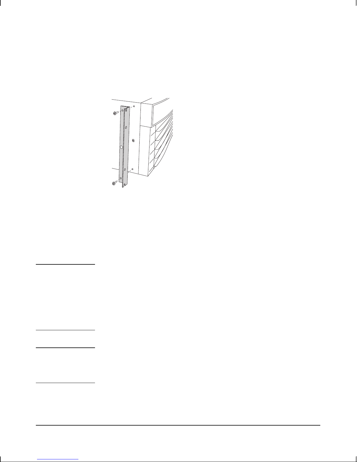
-Frt(ports) Assembly instructions")