SECTION
III
OPERATING INSTRUCTIONS
3-1
m
=~=::
OU~~~/~~2~:
"If"
_---
........
1
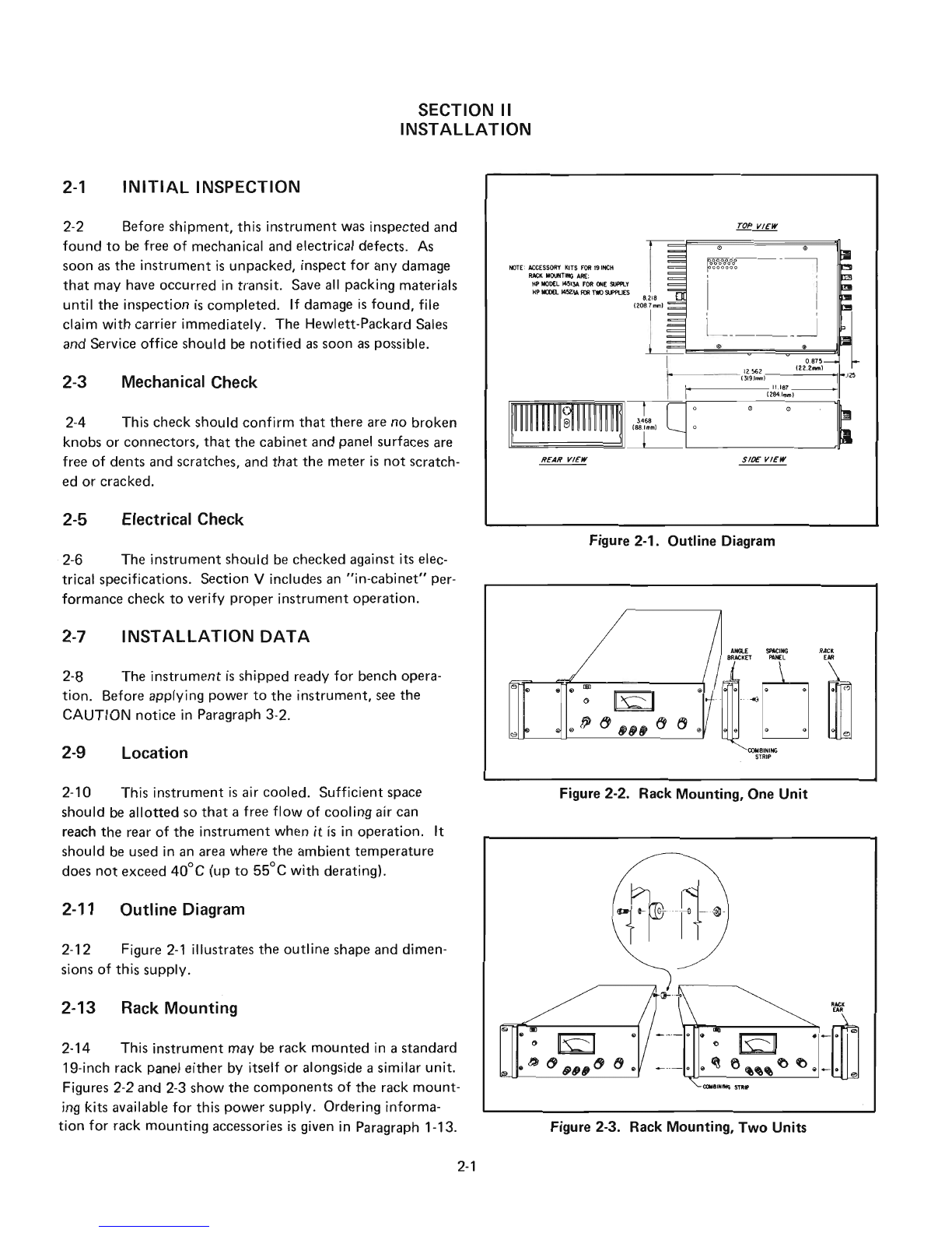
Figure 3-1. Controls and Indicators
TURN-ON CHECKOUT PROCEDURE
a.
Connect
line
cord
to
power
source
and
turn
LINE
switch
G)
on.
LINE ON
indicator
®will light.
b.
Set
METER
switch
®
to
the
+6V
position
and,
with
no
load
connected,
vary
+6V
VOLTAGE-control
@over
its range
and
check
that
the
voltmeter
responds
to
the
con-
trol
setting
and
the
ammeter
indicates
zero.
c.
Set
the
+6V
VOLTAG E
control
for
a
6-volt
meter
indication
and
short
the
+6V
output
terminal
to
COM
(common)
terminal
®
with
an
insulated
test
lead.
The
ammeter
should
indicate
a
short-circuit
output
current
of
approximately
1.0A
(1.1A
in
the
6237A).
Remove
the
short
from
the
output
terminals.
d.
Set
the
METER
switch
to
the
+20V
position
and,
with
no
load
connected,
vary
±20V
VOLTAGE
control
®
over its range
and
check
that
the
voltmeter
responds
to
the
control
setting
and
the
ammeter
indicates
zero.
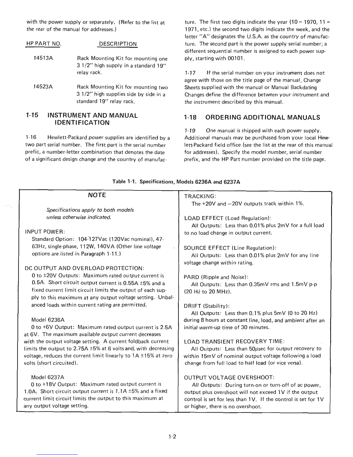
3-2
The
following
steps
describe
the
use
of
the
Model
6236A
or
6237
A
front
panel
controls
and
indicators
illus-
trated
in Figure 3-1
and
serve as a
brief
check
that
the
sup-
ply
is
operational.
This
checkout
procedure
or
the
more
detailed
performance
test
of
Paragraph 5-6
should
be follow-
ed
when
the
instrument
is
received
and
before
it
is
connect-
ed
to
any
load
equipment.
Proceed
to
the
more
detailed
procedures
beginning in Paragraph 5-6 if
any
difficulties
are
encountered.
--
CAUTION--
e.
Set
the
±20V
VOLTAGE
control
for
a
20-volt
meter
indication
and
short
the
+20V
output
terminal
to
the
com-
mon
terminal
with
an
insulated
test
lead.
The
ammeter
should
indicate
a
short-circuit
output
current
of
O.55A
±5%.
Remove
the
short
from
the
output
terminals.
f.
Repeat
steps
(d)
and
(e),
but
substitute
the
-20V
position
of
the
METER
switch
and
the
-20V
output
ter-
minal.
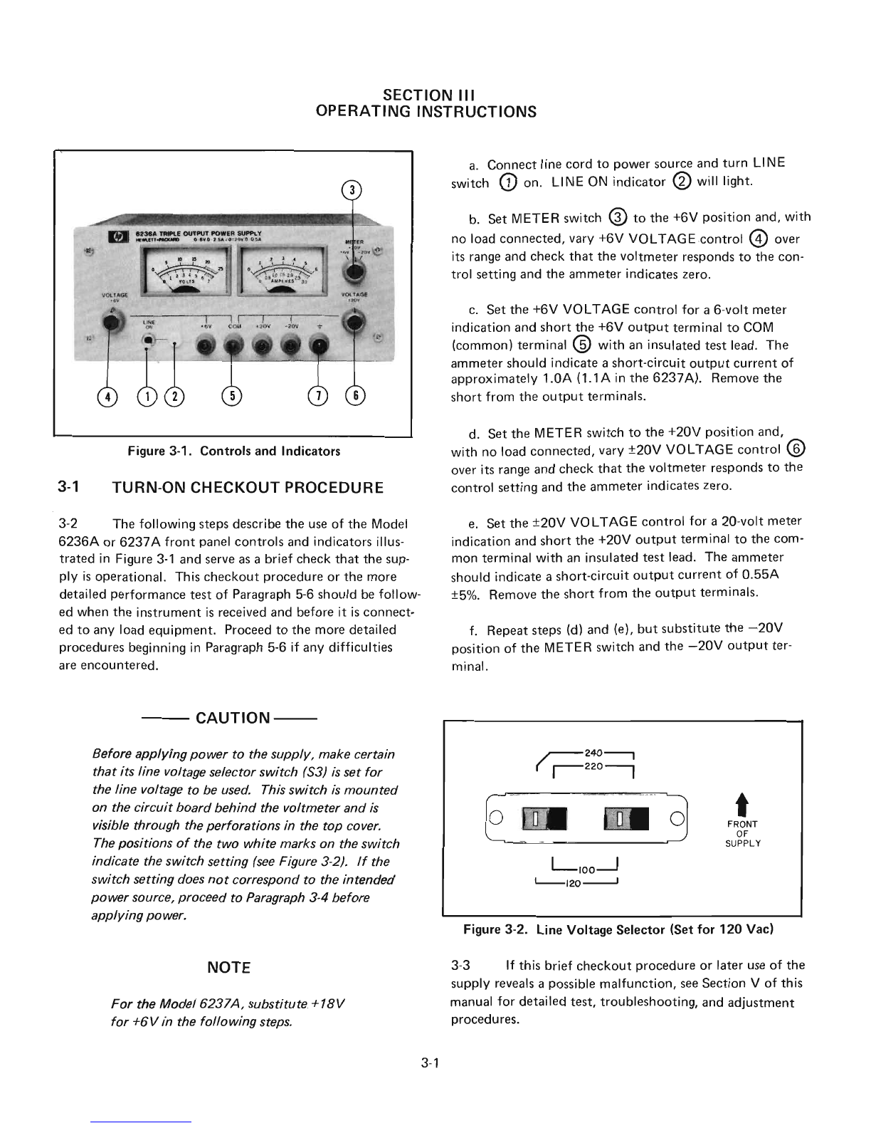
Figure 3-2. Line Voltage Selector (Set for
120
Vac)
Before applying power to the supply, make certain
that its line voltage selector switch
(53)
is
set
for
the line voltage to be used. This switch
is
mounted
on the circuit board behind the voltmeter and
is
visible through the perforations in the top cover.
The positions
of
the two white marks on the switch
indicate the switch setting
(see
Figure 3-2).
If
the
switch setting does
not
correspond to the intended
power source, proceed to
Paragraph
3-4 before
applying power.
.r--
240----,
(
r-
220
----,
0_
0
L-,OO--.J
'---120
---J
t
FRONT
OF
SUPPLY
NOTE
For the Model 6237A, substitute. +18V
for +6Vin the following steps.
3-1
3-3
If
this
brief
checkout
procedure
or
later
use
of
the
supply
reveals apossible
malfunction,
see
Section
V
of
this
manual
for
detailed
test,
troubleshooting,
and
adjustment
procedures.