After the instrument
is
unpacked,
it
should be inspected for damage
re-
ceived in transit.
lined in the "Claim for Damage in Shipment" page
at
the back of this instruction
book.
If
any shipping damage
is
found, follow the procedure out-
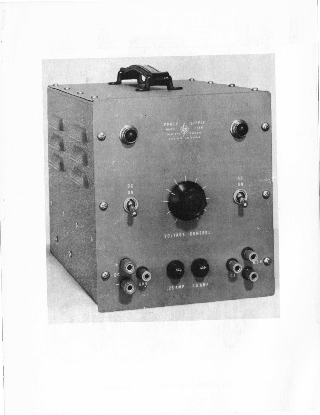
Controls and Terminals
--
DC
ON
-
This switch controls the direct current supplied to the DC
binding posts and indicator lamp which
is
lighted while there
is
voltage on
these binding posts.
AC
ON
-
This switch controls the power supplied to the instrument from
the power line.
VOLTAGE CONTROL
-
This variable resistor varies the direct current
output voltage.
FUSE
.25
AMP
-
The fuseholder, located on the control panel, contains
The fuse may be replaced by unscrewing the fuse-
a
-25
ampere cartridge fuse.
holder cap and inserting
a
new fuse.,
FUSE
1.
6
AMP
-
The fuseholder, located on the control panel, contains
The fuse may be replaced by unscrewing the fuse-
a
1.6
ampere cartridge fuse.
holder cap and inserting
a
new fuse.
a
230
V
power line, an
.8
ampere fuse should be used.
this instrument must be of the "Slo-blo" type
as
specified in the Replaceable
Parts List.
Whenever the instrument
is
operated from
Replacement fuses for
tDC
-B
GND
-
These three binding posts are the DC output terminals and
the chassis ground terminal.
CT,
6.
3V
-
These three binding posts are connected directly to the
6.
3V
secondary of the power transformer.
tap of this secondary. The CT terminal
is
connected to the center
Power Cable
-
The power cable consists
of
three conductors. Two of
these conductors carry power to the instrument while the third conductor (green
wire)
is
connected to the instrument chassis. The third wire projects from the
cable near the plug end of the cable and may be connected to
a
ground when it
is
desirable to have
a
grounded instrument chassis,
Operation
--
CAUTION
-
AVOID ELECTRIC SHOCK
BY
TURNING THE
DC
SWITCH
TO THE OFF POSITION BEFORE
MAKING
ANY CONNECTIONS.
,
-2
-