HPE G2 R5000 3U User manual

HPE G2 R5000/6000 3U UPS
User Guide
Part Number: P12219-003
Published: September 2020
Edition: 3
Abstract
This document includes installation, configuration, and operation information for the HPE G2 R5000/R60003U UPS . This
document is for the person who installs and maintains power products. Hewlett Packard Enterprise assumes you are qualified
in the servicing of high-voltage equipment and trained in recognizing hazards in products with hazardous energy levels.

©Copyright 2019, 2020 Hewlett Packard Enterprise Development LP
Notices
The information contained herein is subject to change without notice. The only warranties for Hewlett Packard Enterprise
products and services are set forth in the express warranty statements accompanying such products and services. Nothing
herein should be construed as constituting an additional warranty. Hewlett Packard Enterprise shall not be liable for technical
or editorial errors or omissions contained herein.
Confidential computer software. Valid license from Hewlett Packard Enterprise required for possession, use, or copying.
Consistent with FAR 12211 and 12212, Commercial Computer Software, Computer Software Documentation, and Technical
Data for Commercial Items are licensed to the U.S. Government under vendor's standard commercial license.
Links to third-party websites take you outside the Hewlett Packard Enterprise website. Hewlett Packard Enterprise has no
control over and is not responsible for information outside the Hewlett Packard Enterprise website.
Acknowledgments
Intel®, Itanium®, Pentium®, Xeon®, Intel Inside®, and the Intel Inside logo are trademarks of Intel Corporation in the U.S. and
other countries.
Microsoft®and Windows®are either registered trademarks or trademarks of Microsoft Corporation in the United States
and/or other countries.
Adobe®and Acrobat®are trademarks of Adobe Systems Incorporated.
Java®and Oracle®are registered trademarks of Oracle and/or its ailiates.
UNIX®is a registered trademark of The Open Group.

Contents
Important safety information .............................................................................................. 6
Personal safety............................................................................................................................................................................................................................ 6
Product safety..............................................................................................................................................................................................................................6
Special precautions................................................................................................................................................................................................................... 7
Component identification...................................................................................................... 8
Overview..........................................................................................................................................................................................................................................8
Front panel components........................................................................................................................................................................................................ 8
UPS front panel controls........................................................................................................................................................................................................9
Front panel LEDs........................................................................................................................................................................................................................9
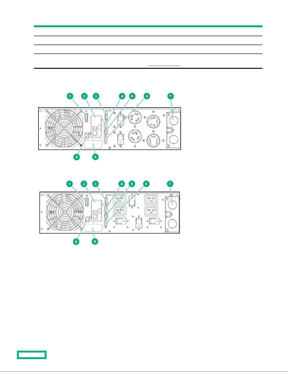
Rear panel components.......................................................................................................................................................................................................10
ERM rear panel components.............................................................................................................................................................................................12
USB communications port..................................................................................................................................................................................................12
Dry contact port.......................................................................................................................................................................................................................12
ROO................................................................................................................................................................................................................................................. 13
RPO port.......................................................................................................................................................................................................................................14
Installation............................................................................................................................. 16
Precautions................................................................................................................................................................................................................................. 16
Preparing to install the hardware.................................................................................................................................................................................. 16
Tools and materials.............................................................................................................................................................................................. 16
Selecting a site.........................................................................................................................................................................................................17
Preparing the equipment.................................................................................................................................................................................. 17
Installing the mounting rails............................................................................................................................................................................................. 18
Installing the UPS....................................................................................................................................................................................................................18
Connecting the battery...................................................................................................................................................................................... 19
Connecting the serial communications port.......................................................................................................................................... 21
Connecting the RPO port..................................................................................................................................................................................21
Connecting the ground bonding cable......................................................................................................................................................22
Connecting the UPS to utility power..........................................................................................................................................................22
Connecting devices to the UPS..................................................................................................................................................................... 24
Charging the UPS batteries............................................................................................................................................................................. 24
Starting power to the load................................................................................................................................................................................26
Installing the ERM...................................................................................................................................................................................................................26
Connecting the ERM to the UPS...................................................................................................................................................................27
Charging the ERM batteries............................................................................................................................................................................ 27
Operations..............................................................................................................................28
Modes of operation................................................................................................................................................................................................................ 28
Standby mode..........................................................................................................................................................................................................28
Online mode..............................................................................................................................................................................................................28
Battery mode............................................................................................................................................................................................................28
Bypass mode............................................................................................................................................................................................................ 28
Configuring the UPS..............................................................................................................................................................................................................29
Changing the language...................................................................................................................................................................................... 29
3

Changing display functions..............................................................................................................................................................................29
Verifying the RPO port connection...............................................................................................................................................................................30
Powering down the UPS......................................................................................................................................................................................................31
Power protector.................................................................................................................... 32
Power protector software...................................................................................................................................................................................................32
Maintenance...........................................................................................................................33
Battery replacement precautions.................................................................................................................................................................................. 33
Replacing the UPS.................................................................................................................................................................................................................. 33
Replacing the ERM................................................................................................................................................................................................................. 34
Replacing the UPS batteries............................................................................................................................................................................................. 34
Replacing the ERM batteries............................................................................................................................................................................................ 36
Updating the UPS firmware.............................................................................................................................................................................................. 38
Troubleshooting....................................................................................................................39
Bypass mode..............................................................................................................................................................................................................................39
Battery low.................................................................................................................................................................................................................................. 39
No battery....................................................................................................................................................................................................................................39
Battery fault................................................................................................................................................................................................................................40
Backup time................................................................................................................................................................................................................................40
Bypass mode..............................................................................................................................................................................................................................40
Power overload.........................................................................................................................................................................................................................41
UPS overtemperature...........................................................................................................................................................................................................41
UPS does not start..................................................................................................................................................................................................................42
I/O bad wiring............................................................................................................................................................................................................................42
Specifications.........................................................................................................................43
UPS physical specifications............................................................................................................................................................................................... 43
ERM physical specifications.............................................................................................................................................................................................. 43
UPS input specifications......................................................................................................................................................................................................43
UPS output specifications.................................................................................................................................................................................................. 44
Power protection specifications....................................................................................................................................................................44
Voltage specifications.........................................................................................................................................................................................44
Output tolerance specifications.................................................................................................................................................................... 44
Output feature specifications.........................................................................................................................................................................44
Battery specifications........................................................................................................................................................................................................... 45
Average battery runtime.................................................................................................................................................................................................... 45
Environmental specifications........................................................................................................................................................................................... 45
RPO port specifications....................................................................................................................................................................................................... 46
UPS spare parts.....................................................................................................................47
Electrostatic discharge.........................................................................................................48
Preventing electrostatic discharge............................................................................................................................................................................... 48
Grounding methods to prevent electrostatic discharge...................................................................................................................................48
Websites................................................................................................................................. 49
4

Support and other resources.............................................................................................. 50
Accessing Hewlett Packard Enterprise Support...................................................................................................................................................50
Accessing updates..................................................................................................................................................................................................................50
Customer self repair...............................................................................................................................................................................................................51
Remote support........................................................................................................................................................................................................................51
Warranty information............................................................................................................................................................................................................51
Regulatory information........................................................................................................................................................................................................52
Documentation feedback....................................................................................................................................................................................................52
5

Important safety information
For important safety, environmental, and regulatory information, see Safety and Compliance Information for Server, Storage,
Power, Networking, and Rack Products, available at the Hewlett Packard Enterprise website.
Personal safety
• The system has its own power source (the battery). Consequently, the power outlets may be energized, even if the system
is disconnected from the AC power source.
• Dangerous voltage levels are present within the system. The system must be opened exclusively by qualified service
personnel.
• The system must be properly grounded.
• The battery supplied with the system contains small amounts of toxic materials.
• There are no user serviceable parts inside the system, except for the replaceable battery.
• To avoid accidents, observe the following directives:
◦Battery hot swap service must be performed by qualified service personnel with knowledge of batteries and the
required precautions.
◦When replacing batteries, replace with the same type and number of batteries or battery packs.
◦Do not dispose of batteries in a fire, the batteries might explode.
◦Batteries constitute a danger (electrical shock, burns). The short-circuit current might be high.
• The following precautions must be taken for all handling:
◦Wear rubber gloves and boots.
◦Do not lay tools or metal parts on top of batteries.
◦Battery removal and/or replacement, by the end user, requires powering down the load and UPS. Consider scheduling a
maintenance window.
Product safety
• The UPS connection instructions and operation described in the guide must be followed in the indicated order.
• To reduce the risk of fire, the unit only connects to a dedicated circuit provided with branch circuit overcurrent protection
with D curve in accordance with the National Electric Code, ANSI/NFPA 70, 30A for R5000, 32A for R6000. The upstream
circuit breaker must be easily accessible. The unit can be disconnected from AC power source by opening this circuit
breaker.
• A means of disconnection and overcurrent protection devices will be provided by others for permanently connected AC
input/output circuits.
• Verify that the indication on the rating plate corresponds to the AC powered system and to the electrical consumption of
all the equipment that will be connected to the system.
• For pluggable equipment, the socket-outlet must be installed near the equipment and must be easily accessible.
• Never install the system near liquids or in an excessively damp environment.
Important safety information 6

• Never let a foreign body penetrate inside the system.
• Never block the ventilation grates of the system.
• Never expose the system to direct sunlight or source of heat.
• If the system must be stored prior to installation, storage must be in a dry place.
• The admissible storage temperature range is 0°C to 40°C (32°F to 104°F).
• The system is not for use in a computer room as defined in the standard for the Protection of Information Technology
Equipment, ANSI/NFPA 75.
Special precautions
• The unit is heavy. Wear safety shoes for handling operations.
• All handling operations will require at least two people, including:
◦Unpacking
◦Lifting
◦Installation in rack system
• Straps are provided only for manually unpacking the unit from the carton. Do not use the straps to carry the unit around.
The unit can slip from the straps during handling resulting in a risk of injury and product damage.
◦Keep 30 cm (12 in) minimum distance between the straps.
◦Lift the unit carefully and keep at a low height.
◦Keep the unit horizontal during unpacking.
• Before and after the installation, if the UPS remains de-energized for a long period, the UPS must be energized for a period
of 24 hours, at least once every six months for a normal storage temperature, less than 25°C (77°F). Energizing the UPS
charges the battery and avoids damage.
• During the replacement of the battery module, it is important to use the same type and number of elements as the original
battery module provided with the UPS to maintain the same level of performance and safety. If there is doubt, contact
Hewlett Packard Enterprise.
• Other than batteries, all repairs and service must be performed by authorized personnel only. There are no user serviceable
parts inside the UPS.
Important safety information 7

Component identification
This chapter describes the external and internal server features and components.
Overview
The HPE G2 R5000/60003U UPS features a 3U rack-mount design and oers power protection for the following loads:
• 5kVA models—5000VA/4500W/09PF
• 6kVA models—6000VA/5400W/ 09PF
To benefit from the latest product enhancements, update to the latest version of the UPS firmware and software.
NOTE: To download the latest versions of the UPS firmware and software, see the Hewlett Packard Enterprise website.
Front panel components
Item Description
1 Battery compartment
2 LED display
3 Control buttons
Component identification 8

UPS front panel controls
Item Description
1 Escape button
2 Up button
3 Down button
4 Enter button
5 Power button
Front panel LEDs
Component identification 9

Item Indicator Status Description
1 Online mode On The UPS is operating normally online or in high eiciency mode.
2 Battery mode On The UPS is on battery mode.
3 Bypass mode On The UPS is in bypass mode.
4 Fault On The UPS has an active alarm or fault. For more information, see
the Troubleshootingsection.
Rear panel components
Figure 1: G2 R5000 4 out NA/JPN model
Figure 2: G2 R5000 5 out NA/JPN model
Component identification 10

Figure 3: G2 R6000 INTL model
Item Description
1 Remote Power O (RPO) terminal block
2 1GB UPS Network Management Module
3 Remote On/O (ROO) terminal block
4 Dry contacts communications port
5 USB communications port
NOTE: This port is used for UPS firmware updates. For more information, see USB communications port.
6 Serial communications port
7 Power I/O interface
8 ERM to UPS connection
9 Automatic battery recognition port (ERM)
Component identification 11

ERM rear panel components
Item Description
1 ERM to UPS connector
2 ERM recognition port
USB communications port
NOTE: This port is only used for firmware upgrades. To update the UPS firmware, see the Hewlett Packard Enterprise
website.
Dry contact port
CAUTION: Before using the dry contact port, the following cautions must be observed:
• The relay output contacts cannot be connected to any utility circuits.
• Reinforced insulation to the utility is required.
• The relay output contacts have a maximum rating of 250VAC/5A.
The UPS has four relay outputs. Each relay output is available with either an open or closed contact.
Component identification 12

Pin Description
1 Not on bypass
2 Load not protected
3 Not low battery
4 Not on battery
5 User common
6 On bypass
7 Low battery
8 Load protected
9 On battery
n.o. Contact normally open
n.c. Contact normally closed
ROO
ROO allows remote action of the power button to switch the UPS on and o.
• When the contact changes from open to closed, the UPS is switched-on (or stays On).
• When the contact changes from closed to open, the UPS is powered o (or stays O).
Component identification 13

Figure 4: This figure displays a normally open contact.
NOTE: The on/o control using the power button has priority over the remote control.
RPO port
RPO is used to shut down the UPS remotely. This feature is primarily used for remotely powering down the UPS if there is an
emergency. When RPO is activated, the UPS shuts down the output and all its power converters immediately. The UPS remains
on to alarm the fault.
The RPO circuit is an IEC 60950 safety extra low voltage (SELV) circuit. This circuit must be separated from any hazardous
voltage circuits by reinforced insulation. The RPO must also meet the following requirements:
• The RPO cannot be connected to any utility connected circuits. Reinforced insulation to the utility is required. The RPO
switch must have a minimum rating of 27 Vdc and 20 mA and be a dedicated latching-type switch not tied into any other
circuit. The RPO signal must remain active for at least 250 ms for proper operation.
• To ensure that the UPS stops supplying power to the load during any mode of operation, the input power must be
disconnected from the UPS when the RPO function is activated.
NOTE: Leave the RPO connector installed in the RPO port on the UPS even if the RPO function is not needed.
The following images illustrate the RPO connections.
Figure 5: Internal power supply
Component identification 14

Figure 6: External power supply
Component identification 15

Installation
Precautions
Save these instructions. This document contains important safety instructions that must be followed during installation,
operation, and maintenance of the UPS and batteries.
WARNING: A risk of personal injury from electric shock and hazardous energy levels exists. The installation of options
and routine maintenance and service of this product must be performed by individuals who are knowledgeable about
the procedures, precautions, and hazards associated with AC power products.
48 106
This symbol indicates that the UPS exceeds the recommended weight for one individual to handle
safely.
68 150
This symbol indicates that the ERM exceeds the recommended weight for one individual to handle
safely.
WARNING: To reduce the risk of personal injury or damage to the equipment, observe local occupational health and
safety requirements and guidelines for manual material handling.
WARNING: To prevent personal injury from earth conductor leakage current:
• Do not operate the UPS while disconnected from the utility power source.
• Disconnect load devices before disconnecting the UPS from the utility power source.
Preparing to install the hardware
Before installing the hardware:
1. Be sure the necessary tools and materials are available.
2. Select an installation site.
3. Prepare the equipment for installation in the rack.
Tools and materials
The following tools are required for installation:
Phillips screwdriver
The following items are supplied with the UPS:
Installation 16

• Screws
• Washers
Selecting a site
WARNING: To prevent fire or electric shock, install the unit in a temperature- and humidity-controlled indoor
environment, free of conductive contaminants.
When selecting a site, consider the following factors:
• Elevated operating ambient temperature—If the equipment is installed in a closed or multiunit rack assembly, the
operating ambient temperature of the rack environment might be greater than room ambient temperature. Install the
equipment in an environment compatible with the operating temperature. For more information, see Environmental
specifications.
• Reduced air flow—In the rack, the rate of air flow required for safe operation of the equipment must not be compromised.
• Circuit overloading—Consideration must be given to the connection of the equipment to the supply circuit and the eect
that overloading of the circuits might have on overcurrent protection and supply wiring. Appropriate consideration of
equipment nameplate ratings must be used when addressing this concern.
• Reliable earthing—Reliable earthing of rack-mounted equipment must be maintained. Particular attention must be given to
supply connections other than direct connections to the branch circuit, such as the use of power strips.
• Electrical requirements—All models require a dedicated (unshared) branch circuit, suitably rated for the specific UPS as
stated in the UPS input specifications.
Preparing the equipment
Procedure
1. Check the battery recharge date specified on the label that is aixed to the shipping carton.
IMPORTANT: Do not use the battery if the recharge date has passed. If the date on the battery recharge date label
has passed without the battery being recharged, contact an HPE authorized service representative for directions.
2. Transport the packaged unit to its installation location.
3. Unpack the equipment near the rack where the unit will be assembled.
CAUTION: Always plan the rack installation so that the heaviest item is on the bottom of the rack. Install the
heaviest item first, and continue to populate the rack from the bottom to the top.
Installation 17

Installing the mounting rails
WARNING: To reduce the risk of personal injury or damage to the equipment, be sure that:
• The leveling feet are extended to the floor.
• The full weight of the rack rests on the leveling feet.
• If it is a single-rack installation, the stabilizing feet are attached to the rack.
• The racks are coupled together in multiple-rack installations.
• Only one component is extended at a time. A rack may become unstable if more than one component is extended for
any reason.
Procedure
1. Extend the brackets to the appropriate length.
2. Insert screws through the rack into the mounting rail and the front and back of each mounting bracket.
Installing the UPS
Before installing the UPS, review and observe all warnings in Precautions.
WARNING: A risk of personal injury or damage to the equipment exists. Uneven loading of equipment in the rack might
cause the rack to become unstable. Install the heavier components first, and then continue to populate the rack from the
bottom to the top.
Procedure
1. Install the mounting rails.
2. With one person on each side of the carton, lift the chassis and lower it to the floor in front of the rack.
3. Install the mounting ears on the chassis using the screws provided.
Installation 18

4. With one person on each side, lift the chassis to rail level and slide the chassis on the mounting rails.
5. Attach the chassis to the rack using the supplied screws.
Connecting the battery
Procedure
1. Remove the bezel from the front of the UPS.
2. Remove the two screws.
Installation 19

3. Press the bezel to the right, and then open the front of the UPS.
4. Connect the battery cables.
Installation 20
This manual suits for next models
1
Table of contents
Other HPE UPS manuals

HPE
HPE R1500 G5 Assembly instructions

HPE
HPE R/T3000 G5 Assembly instructions

HPE
HPE R/T2200 G4 User manual

HPE
HPE G2 R5000 User manual

HPE
HPE R/T2200 G5 Assembly instructions

HPE
HPE R/T3000 G5 Assembly instructions

HPE
HPE T750 G5 NA/JP Tower User manual

HPE
HPE R/T3000 G2 User manual

HPE
HPE R1500 User manual