HT SOLAR-02 User manual

ENGLISH
User manual
©Copyright HT ITALIA 2021 Release EN 3.01 - 06/09/2021

SOLAR-02
TABLE OF CONTENTS
1. INTRODUCTION .............................................................................................................2
2. PRECAUTIONS AND SAFETY MEASURES ..................................................................3
2.1. Preliminary instructions......................................................................................................4
2.2. During use .........................................................................................................................4
2.3. After use ............................................................................................................................4
3. PREPARATION FOR USE...............................................................................................4
3.1. Initial inspections ...............................................................................................................4
3.2. Power supply .....................................................................................................................4
3.3. Storage ..............................................................................................................................5
4. DESCRIPTION OF THE REMOTE UNIT SOLAR-02 ......................................................5
4.1. Description of controls .......................................................................................................5
4.2. Description of function keys...............................................................................................5
4.3. Conditions when turning on ...............................................................................................6
5. USING THE REMOTE UNIT SOLAR-02 .........................................................................6
5.1. General ..............................................................................................................................6
5.2. Programming THE remote unit SOLAR-02........................................................................7
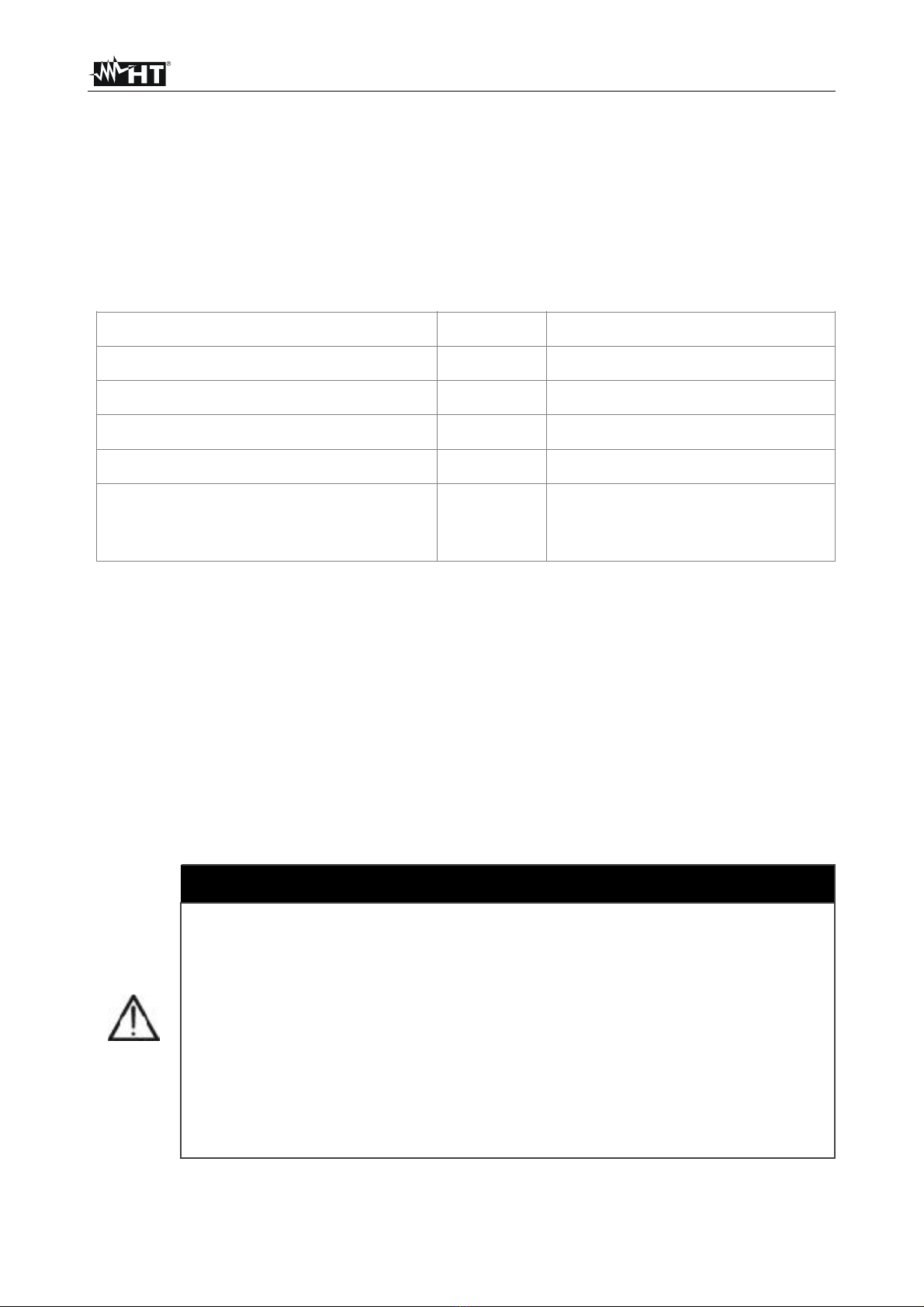
5.2.1. Setting the values of sensor 1 (PYRA or MONO) ..................................................................8
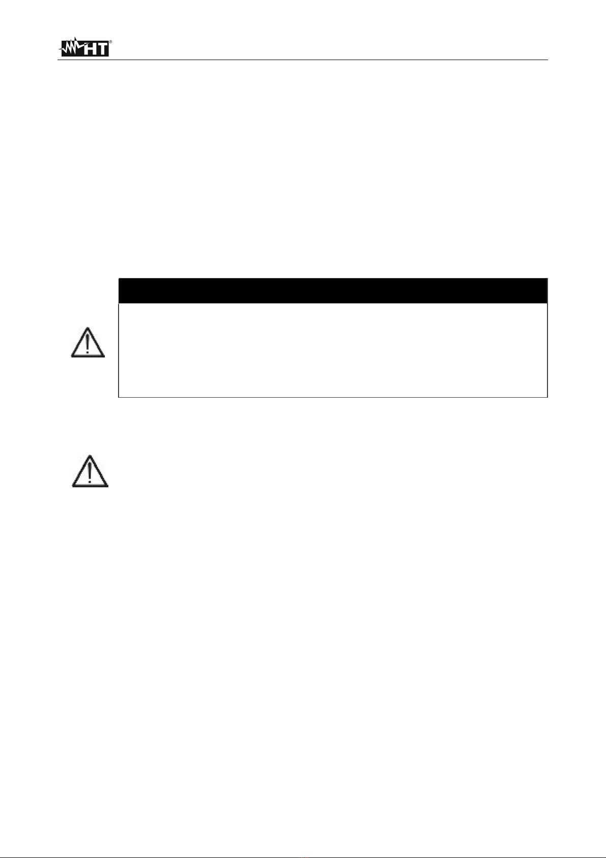
5.2.2. Setting the values of sensor 2 (MULTI) ..................................................................................9
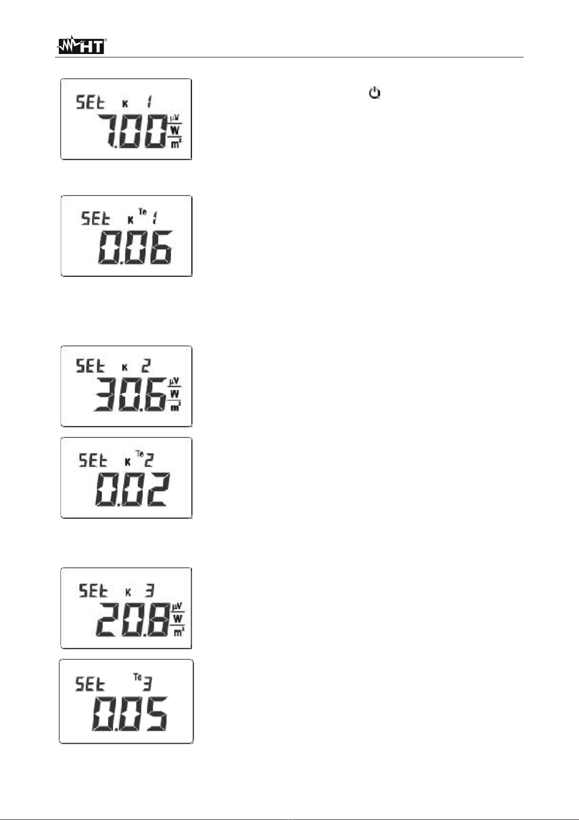
5.2.3. Setting the values of sensor 3................................................................................................9
5.3. Using the SOLAR-02 in independent mode.....................................................................11
5.4. Using the inclinometer function........................................................................................11
5.5. Using the SOLAR-02 with master instrument type “M-USB” ...........................................12
5.5.1. Preliminary check.................................................................................................................12
5.5.2. Use of the unit ......................................................................................................................12
5.6. Using the SOLAR-02 with master instrument type “M-RF”..............................................14
5.6.1. Preliminary check.................................................................................................................14
5.6.2. Use of the unit ......................................................................................................................15
6. MAINTENANCE.............................................................................................................18
6.1. General information .........................................................................................................18
6.2. Replacing the batteries ....................................................................................................18
6.3. Cleaning...........................................................................................................................18
6.4. End of life.........................................................................................................................18
7. TECHNICAL SPECIFICATIONS....................................................................................19
7.1. Technical specifications ...................................................................................................19
7.2. General characteristics ....................................................................................................19
7.3. Environmental conditions.................................................................................................19
7.4. Accessories .....................................................................................................................21
8. SERVICE ......................................................................................................................22
8.1. Warranty conditions .........................................................................................................22
8.2. Service.............................................................................................................................22
EN - 1

SOLAR-02
1. INTRODUCTION
The remote unit SOLAR-02 has been designed to measure irradiation [W/m2] and
temperature [°C] by means of appropriate probes connected to it. It can also be used in
combination with a MASTER instrument to carry out the above-mentioned measurements
for testing/recording the efficiency of single-phase and three-phase photovoltaic
installations.
The unit SOLAR-02 can be connected to the following accessories and MASTER
instruments:
Table 1: List of master instruments and accessories
For the sake of brevity, in this manual, the master instruments and the accessories
are indicated with the acronym given in column “Acronym” of the previous Table 1
The unit SOLAR-02 has the following functions:
➢Real-time display of irradiation and temperature values of PV module cells and
environment
➢Connection with a irradiation sensor type Irr-P or reference cell type Irr-S2
➢Connection to master unit via USB connection (M-USB) or radio frequency connection
(M-RF)
➢Synchronization with master unit M-USB or M-RF when starting testing/recording.
➢Measurement of the tilting angle of PV panels
Description
Acronym
HT model
Pyranometer
Irr-P
HT303, HT303N
Irradiation sensor with 2 silicon cells
Irr-S2
HT304, HT304
Temperature sensor
Tmp
PT300N
Master instrument - USB connection
M-USB
SOLAR300, SOLAR300N
Master instrument - RF connection
M-RF
SOLAR I-V, SOLAR I-Vw,
SOLAR I-Ve,I-V400,I-V400w,I-
V500w, PVCHECK, PVCHECKs
CAUTION
•The remote unit SOLAR-02 is a measuring instrument capable of using
radio frequency for data transfer. For internal reasons it was been
adopted a 2.4GHz harmonized frequency band. The above said radio
based device is built under Class 1 according to the Agreement
stipulated among EEC and EFTA countries, as defined by ERC/REC
70-03 protocols
•About a WiFi portable devices the European standards dictate
maximum radiated transmit power of 100mW EIRP and frequency
range 2.400 ÷2.4835GHz. In France these types of equipment must be
restricted to the 2.4465 ÷2.4835GHz frequency range and must be
restricted to indoor use
EN - 2

SOLAR-02
2. PRECAUTIONS AND SAFETY MEASURES
The instrument was designed in compliance with the requirements of R&TTE Directive as
well as of harmonized directives for electronic measuring instruments. Before and during
measurements, carefully observe the following instructions:
•Do not perform any measurement in humid environments, in the presence of gas or
explosive or inflammable material or in dusty areas.
•Avoid any contact with the circuit to be tested if no measurements are being carried
out.
•Avoid any contact with exposed metal parts, with unused measuring leads, circuits, etc.
•Do not perform any measurement when anomalies are found in the instrument, such as
deformations, breaks, substance leaks, no display view, etc.
•Only use HT original accessories.
In this manual, the following symbol is used:
CAUTION
In accordance with the recommendations of the European Council
1995/519/EC and the standard EN62311, the instrument can be used
safely while you are holding it in your hands. Under this circumstance
power levels with 2.4GHz transmission are thoroughly covered as per the
basic restrictions for human exposure to RF according to the above
mentioned European rules
Warning: observe the instructions reported in the manual. An improper use
could damage the instrument or its components
EN - 3

SOLAR-02
2.1. PRELIMINARY INSTRUCTIONS
•This instrument has been designed for use in the environmental conditions specified in § 7.3
•We recommend following the usual safety rules to protect yourself from dangerous
voltages and currents and to protect the instrument against improper use
•Do not apply any voltage to the instrument’s inputs
•Only the accessories supplied with the instrument guarantee safety standards. They must
be in good conditions and replaced, if necessary, with identical models
•Do not subject the input connectors of the instrument to strong mechanical stress
•Check that the batteries are correctly inserted
2.2. DURING USE
We recommend carefully reading the following recommendations and instructions:
2.3. AFTER USE
When measurements are completed, turn off the instrument by pressing and holding the
ON/OFF key for some seconds. If the instrument is not to be used for a long time, remove
the batteries and follow the instructions given in § 7.3
3. PREPARATION FOR USE
3.1. INITIAL INSPECTIONS
Before shipment, the instrument’s electronics and mechanics have been inspected. All
possible precautions have been taken in order for the instrument to be delivered without
damage. However, we recommend generally inspecting the instrument in order to detect
any damage suffered during transport. Should you detect any anomalies, immediately
contact the forwarding agent. Moreover, we recommend checking that the package
contains all parts listed in § 0. Should you find any discrepancy, please contact the dealer.
Should it become necessary to return the instrument, please follow the instructions
reported in § 8
3.2. POWER SUPPLY
The instrument is supplied by 4 x 1,5V batteries type IEC LR03 AAA. When batteries are
almost flat, the symbol “ ” appears on the display. To replace the batteries, see § 6.2
CAUTION
The RF connection of remote unit SOLAR-02 is normally disabled for
default. For use of this unit with the Master meter “M-RF” (see Table
1) is necessary to activate the RF connection (see § 5.6.1)
CAUTION
•Failure to observe the warnings and/or instructions may damage the
instrument and/or its components or generate a danger for the operator.
•The symbol “ ” indicates that the batteries are flat. Stop testing and
replace the batteries according to the procedure described in § 6.2
•When the instrument is connected to the circuit being tested, never touch
any lead, even if unused.
EN - 4

SOLAR-02
3.3. STORAGE
In order to guarantee precise measurements, after a long storage period, in extreme
environmental conditions, wait for the instrument to return to normal conditions (see § 7.3)
4. DESCRIPTION OF THE REMOTE UNIT SOLAR-02
4.1. DESCRIPTION OF CONTROLS
Fig. 1: Description of the remote unit SOLAR-02
4.2. DESCRIPTION OF FUNCTION KEYS
CAPTION:
1. LCD display
2. /ESC key
3. SET key
4. PYRA/CELL input
5. TEMP input
6. arrow key
7. FUNC/key
8. USB port for connection to
master instrument M-USB
This key has a double function of turning ON/OFF the unit and of
returning to the previous screen (ESC)
The SET key allows a rapid selection of the sensitivity of the
solarimeter/reference solar cell in use
This key has a double function of increasing (), which can be
used when programming, and of passing from the display of the
environmental temperature Te to the display of the tilting angle
(FUNC).
The key is used when programming the unit to set the parameter
values,
EN - 5

SOLAR-02
4.3. CONDITIONS WHEN TURNING ON
5. USING THE REMOTE UNIT SOLAR-02
5.1. GENERAL
The remote unit SOLAR-02 can be used in the following modes:
1. Independent operation without connection to any master instrument for measuring in
real time the values of irradiation, cell temperature and environmental temperature on
PV installations. To this purpose, the unit accepts, as inputs:
For irradiation measurement (expressed in W/m2- PYRA/CELL input):
➢Solarimeter probe with thermobattery type Irr-P (see Table 1)
➢Double reference silicon cell type Irr-S2 (see Table 1)
For module and environmental temperature measurement (expressed in °C – TEMP
input)
➢Temperature probe type Tmp (see Table 1)
2. Operation for testing/recording synchronized with a master instrument for measuring
and saving irradiation and temperature values of cells and environment. The type of
connection with the master instruments is the following:
➢Connection via USB cable C2007 Master instrument type M-USB (see Tab l e 1)
➢Connection with radio frequency (RF) Master instrument type M-RF (see Tab l e 1)
According with settings receveid by MASTER instrument, SOLAR-02 display a Tc value:
➢Measured by the temperature probe “Tmp” (see Table 1)
➢Calcuted using NOCT (set in MASTER instrument), Irradiance and Environment
Temperature measured by SOLAR-02 according to relationship
where:
Tenv= Environment Temperature
Gp= Irradiance measured
NOCT= Normal Operating Cell Temperature
1. Press the /ESC key to turn on the instrument
2. After the initial screen, where all display symbols appear,
the screen beside, relevant to the loaded firmware version
(FW, e.g. 4.01), is displayed by the unit for a few seconds
3. The screen beside is displayed in order to show that no
probe is connected. From this moment on it is possible to
use the unit
4. Press and hold the /ESC key for a few seconds to turn
off the unit
( ) 800
G
20TenvTcel p
×−+= NOCT
CAUTION
EN - 6

SOLAR-02
5.2. PROGRAMMING THE REMOTE UNIT SOLAR-02
In order to obtain correct irradiation measurement results, it is necessary to carry out a
correct preliminary setting of the sensitivity values of the probes connected to the PYRA/
CELL input of the unit. The set values will be read and considered by the master
instruments upon testing/recording and will be kept by the SOLAR-02 even when the unit
is turned off, until they are modified.
The unit SOLAR-02 allows setting the parameters of max 3 irradiation sensors. In detail:
➢The use of a sensor type Irr-S2 requires setting the sensitivity (K) expressed in mV/
kW*m-2 or in µV/W*m-2 and the parameter Alpha expressed in %/°C for the various types of
silicon (monocrystalline, polycristalline, etc.)
➢The use of a sensor type Irr-P requires setting the sensitivity (K) expressed in mV/
kW*m-2 or in µV/W*m-2. The parameter Alpha expressed in %/°C is ignored.
The presence of “K” symbol on the left of “Tc” temperature value,
indicates that the Cell temperature (Tc) value displayed is not a measured
value buti s a calculated value according with previous relationship.
When the SOLAR-02 is switched on (before connection to MASTER
instrument) the Tc value is the measured value.
EN - 7

SOLAR-02
5.2.1. Setting the values of sensor 1 (PYRA or MONO)
EN - 8

SOLAR-02
5.2.2. Setting the values of sensor 2 (MULTI)
5.2.3. Setting the values of sensor 3
4. With sensor type Irr-P, press the ESC key to exit the
programming mode, saving the changes made. In case a
sensor type Irr-S2 is used, it is necessary to set the
parameter “Alpha” instead.
5. Use the arrow keys and to set the value of Te
(Alpha) corresponding to the value of sensitivity K
previously set.
6. Press the SET key to confirm the value and go on setting
sensor 2.
1. Press and hold the SET key while turning on the
instrument by means of the /ESC key. The unit shows
the screen beside.
2. Use the arrow keys and to set the correct K
sensitivity value reported on the (front or rear) label,
located on the sensor itself.
3. Press the SET key to confirm the value.
1. Use the arrow keys and to set the correct K
sensitivity value reported on the (front or rear) label,
located on the sensor itself.
2. Press the SET key to confirm the value.
3. Use the arrow keys and to set the value of Te
(Alpha) corresponding to the value of sensitivity K
previously set.
4. Press the SET key to confirm the value.
1. With sensor type Irr-S2, press the ESC key to exit the
programming mode, saving the changes made.
2. Use the arrow keys and to set the correct K
sensitivity value reported on the (front or rear) label,
located on the sensor itself.
3. Press the SET key to confirm the value.
4. Use the arrow keys and to set the value of Te
(Alpha) corresponding to the value of sensitivity K
previously set.
5. Press the SET key to confirm the value and to exit the
programming mode, saving the changes made.
EN - 9

SOLAR-02
EN - 10

SOLAR-02
5.3. USING THE SOLAR-02 IN INDEPENDENT MODE
5.4. USING THE INCLINOMETER FUNCTION
5. Position the irradiation measuring probe type “Irr-P” or
“Irr-S2” (see Table 1) on the modules’ surface and
connect the relevant output lead to the PYRA/CELL input
of the unit SOLAR-02
6. Fasten the temperature probe type Tmp with adhesive
tape (see Table 1) on the rear side of the modules and
connect the relevant output lead to the TEMP input of the
unit SOLAR-02
7. Read on the display, in real time, as shown in the figure
beside, the values of:
➢Irradiation on the main display, expressed in W/m2
➢Tc = temperature of cells expressed in °C
➢Te = temperature of environment expressed in °C
1. Turn on the instrument by pressing the /ESC key.
2. Press the SET key. The unit shows the screen beside in
which the K value of the currently set sensor is selected.
3. Use the arrow keys and to select the desired type of
sensor considering the unit programming (see § 0)
4. Confirm selection with the SET key to go back to the
measuring mode
2. Press the FUNC/key to activate the inclinometer mode
of the unit SOLAR-02 instead of the measurement of
temperature Te as shown on the screen beside
3. Fasten the unit on the module’s surface, if necessary by
means of the two magnets available on the rear side
4. Wait for a few seconds
5. Read, in real time, the value (expressed in °) of the tilting
angle against the horizontal plane of the object to be
tested
1. Turn on the unit by pressing the /ESC key. The display
shows the following screen
EN - 11

SOLAR-02
5.5. USING THE SOLAR-02 WITH MASTER INSTRUMENT TYPE “M-USB”
For the definitions of the instrument types, see Table 1. For the use, functions and
activation of a testing/recording on the master instrument, please see the user manual of
the master instrument itself.
5.5.1. Preliminary check
For the “M-USB” master instruments the enable of internal RF module is NOT necessary.
Check that the parameter which enable/disable the RF module should be corrected set at
the first usage of the unit in the herewith way:
5.5.2. Use of the unit
1. Place the Irradiance probe (Irr-P or Irr-S2 – see Table 1) parallel to PV modules surface
and connect the output connector to SOLAR-02 PYRA/CELL input
2. Using a tape fix the temperature probe (Tmp – see Table 1) on the backside of the
module and connect the output connector to SOLAR-02 TEMP input
By press and hold the FUNC/key while switching on the
meter by /ESC key. The message “rFOFF” is displayed for a
few seconds. If the message “rFON” is displayed switch off the
unit and repeat the operation. Afterwards the initial screen is
displayed by the meter. The setting of “RF” parameter is
maintained also during the replace of batteries
1. Switch on the unit and press the SET key. The unit shows
the screen beside in which sensor 1 is selected
2. Use the arrow keys and to select the desired type of
sensor considering the unit programming (see § 5.2)
3. Confirm selection with the SET key to go back to the
measuring mode
4. Connect the unit SOLAR-02 to the master instrument by
means of the USB cable. The symbol “USB” is shown on
the display while the unit is detected by the master
instrument
5. By activating a testing/recording on the master
instr u m ent, the u n i t SOLAR- 0 2 w aits for t h e
synchronization, showing the message “HoLd” on the
display and the indication of the waiting time necessary
before being able to activate the testing procedures (see
example in the screen beside)
6. Once the waiting phase (HOLD) has ended, the message
“Recording…” will be displayed. It is now possible to
disconnect the USB cable from the unit SOLAR-02 and
take the unit near the PV modules. Possible hyphens “- -
-” indicate that no irradiation and temperature probes are
connected to the unit SOLAR-02 yet
EN - 12

SOLAR-02
9. Upon reaching an irradiation value higher that the
threshold set by the MASTER instrument, the unit
SOLAR-02 shows the message “READY” on the display
10.Disconnect the irradiation and temperature probes,
connect the unit to the master instrument again by means
of the USB cable
11. Upon detecting the control to stop testing/recording from
the master instrument, the unit stops working, shows on
the display the message “SEnd” and sends the data to
the master instrument to determine the final result of the
testing
EN - 13

SOLAR-02
5.6. USING THE SOLAR-02 WITH MASTER INSTRUMENT TYPE “M-RF”
For the definitions of the instrument types, see Table 1. For the use, functions and
activation of a testing/recording on the master instrument, please see the user manual of
the master instrument itself.
5.6.1. Preliminary check
For the “M-RF” master instruments the enable of internal RF module IS NECESSARY.
Check that the parameter which enable/disable the RF module should be corrected set at
the first usage of the unit in the herewith way:
By press and hold the FUNC/key while switching on the
meter by /ESC key. The message “rFON is displayed for a
few seconds. If the message “rFOFFis displayed switch off the
unit and repeat the operation. Afterwards the initial screen is
displayed by the meter. The setting of “RF” parameter is
maintained also during the replace of batteries
EN - 14

SOLAR-02
5.6.2. Use of the unit
1. Place the Irradiance probe (Irr-P or Irr-S2 – see Table 1) parallel to PV modules surface
and connect the output connector to SOLAR-02 PYRA/CELL input
2. Using a tape fix the temperature probe (Tmp – see Table 1) on the backside of the
module and connect the output connector to SOLAR-02 TEMP input
2. Press the SET key. The unit shows the screen beside in
which sensor 1 is selected.
3. Use the arrow keys and to select the desired type of
sensor considering the unit programming (see § 5.2)
4. Confirm selection with the SET key to go back to the
measuring mode
5. With operative RF connection, by activating a testing/
recording on the master instrument, the unit SOLAR-02
waits for the synchronization, showing the message
“HoLd” on the display and the indication of the time during
which it is necessary to keep the unit SOLAR-02 near the
master instrument before being able to activate the testing
procedures
6. Once the waiting phase (HOLD) has ended, the message
“Recording…” will be displayed. It is now possible to take
the unit SOLAR-02 away from the master instrument and
take it near the PV modules. Possible hyphens “- - -”
indicate that no irradiation and temperature probes are
connected to the unit SOLAR-02 yet
1. Switch on and approach the unit SOLAR-02 to the master
instrument (max distance 1m). The symbol “ ”:
➢Is blinking approx 30s at display while searching a M-
RF master unit
➢Is fixed at display when a M-RF master unit is found
➢Disappears from display if no M-RF master unit is
found within approx 30s. Press the key for re-start a
new search of a “M-RF” master unit
EN - 15

SOLAR-02
EN - 16

SOLAR-02
9. Upon reaching an irradiation value higher that the
threshold set by the MASTER instrument, the unit
SOLAR-02 shows the message “READY” on the display
10.Disconnect the irradiation and temperature probes and
take the unit again near the master instrument in order to
activate the RF connection
10.Upon detecting the control to stop testing/recording from
the master instrument, the unit stops working, shows on
the display the message “SEnd” and sends the data to the
master instrument to determine the final result of the
testing
11. Approach the unit SOLAR-02 to the master instrument
(max distance 1m):
➢If the “ ” symbol is blinking at display wait for the
reciprocal detection of both units and after this the
symbol is fix at display
➢If the “ ” is missed at display press the key for re-
start a new search of a “M-RF” master unit
EN - 17

SOLAR-02
6. MAINTENANCE
6.1. GENERAL INFORMATION
1. To prevent possible damage or dangers during the accessory’s use or storage,
carefully observe the recommendations listed in this manual.
2. Do not use the accessory in environments with high humidity levels or at high
temperatures. Do not directly expose to sunlight.
3. If the accessory is to be left unused for a long time, remove the batteries to prevent any
leaks of liquids which could damage the internal circuits.
6.2. REPLACING THE BATTERIES
The presence of the symbol “ ” on the display indicates that the internal batteries are
flat and must be replaced. To this purpose, proceed as follows:
1. Turn off the remote unit SOLAR-02
2. Remove any probe from the inputs and the USB cable, if present
3. Open the cover of the battery compartment on the rear side of the accessory
4. Remove the flat batteries and replace them with the same number of batteries of the
same type (see § 7.2), observing the indicated polarities.
5. Restore the cover of the battery compartment into place.
6. Do not scatter flat batteries in the environment. Use the appropriate containers for
disposal.
The instrument is capable of keeping the data stored also without batteries.
6.3. CLEANING
To clean the accessory, use a soft dry cloth. Never use humid cloths, solvents, water, etc.
6.4. END OF LIFE
CAUTION: the symbol reported on the accessory and on the batteries
indicates that the appliance and the batteries must be disposed of separately
and treated correctly.
EN - 18

SOLAR-02
7. TECHNICAL SPECIFICATIONS
7.1. TECHNICAL SPECIFICATIONS
Accuracy is referred to reference conditions: 23°C, <80%RH
Irradiation – PYRA/CELL input
K = sensitivity of the probe used to measure irradiation (expressed in mV/kW/m2 or in uV/W/m2)
K = sensitivity of the probe used to measure irradiation (expressed in mV/kW/m2 or in uV/W/m2) ; Input Vmax = 5V
Temperature – TEMP input (measured with “Tmp” temperature probe – see Table 1)
Input Vmax = 5V
Tilting angle
7.2. GENERAL CHARACTERISTICS
Display
Characteristics: 4 LCD (2000 dots), decimal comma and point
Power supply
Batteries: 4x1,5V alkaline type AAA LR03
Duration of batteries: approx. 480 hours
Auto Power OFF: after 5 minutes of idleness (not in rec. oper.)
Radio module specifications
Frequency range: 2.400 ÷2.4835GHz
R&TTE category: Class 1
Max transmission power: 30µW
Input connectors
USB port: USB 2.0
PYRA/CELL and TEMP inputs: type Hypertac
Internal memory
Autonomy: approx. 1.5 hours (@ PI master = 5s)
Mechanical characteristics
Dimensions (L x W x H): 120 x 65 x 35mm (5 x 3 x 1in)
Weight (batteries included): 215g (8ounces)
7.3. ENVIRONMENTAL CONDITIONS
Reference temperature: 23°C ±5°C ; (73°F ±41°F)
Operating temperature: 0°C ÷40°C ; (32°F ÷104°F)
Relative operating humidity: <80%RH
Storage temperature: -10°C ÷60°C ; (14°F ÷140°F)
Storage humidity: <80%RH
Range [W/m2]
Resolution [W/m2]
Accuracy
0 ÷1400
1 + INT (100 * 0.1/K)
±[1.0%reading + INT(1000 * 0.1/K) dgt]
Probe sensitivity
Range [mV]
Resolution [mV]
Accuracy
K<10
0.00 ÷15.00
0.01
±(1.0%reading+0.1mV
)
K≥10
0.00 ÷65.00
0.02
Range [°C]
Resolution [°C]
Accuracy
-20.0 ÷99.9
0.1
±(1.0%reading + 1°C)
Range [°]
Resolution [°C]
Accuracy
0 ÷90
1
±(1.0%reading +1°)
EN - 19
Other manuals for SOLAR-02
2
Table of contents
Other HT Measuring Instrument manuals
Popular Measuring Instrument manuals by other brands

Bacharach
Bacharach Comfort Chek 400 Operation manual

Endress+Hauser
Endress+Hauser Prosonic S FMU90 PROFIBUS DP operating instructions

Chauvin Arnoux
Chauvin Arnoux C.A 852 user manual

Thyracont
Thyracont VD8 Series operating instructions

Anritsu
Anritsu MS2690A Operation manual

Bender
Bender ISOMETER isoES425 manual