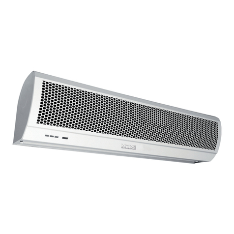
HTW SA2 Series Service manual

ES
EN
FR
PT
IT
MANUAL DE USUARIO E INSTALACIÓN
OWNER’S AND INSTALLATION MANUAL
MANUEL DE L’UTILISATEUR ET D’INSTALLATION
MANUAL DO UTILIZADOR E INSTALAÇÃO
MANUALE UTENTE E INSTALLAZIONE
Por favor lea atentamente este manual antes de usar este producto.
Please, read carefully this manual before using the product.
Avant d’utiliser l’équipement, lisez attentivement les instructions.
Por favor leia atentamente este manual antes de usar o equipamento.
Per favore leggere attentamente questo manuale prima di utilizzare questo prodotto.
Gracias | Thank you | Merci | Obrigado | Grazie
HTW-AC9-1800SA2 | HTW-AC12-2400SA2
HTW-AC15-3000SA2 | HTW-AC20-4000SA2
SA2
CORTINA DE AIRE | AIR CURTAIN | RIDEAU D’AIR
CORTINA DE AR | BARRIERA D’ARIA


MANUAL DE USUARIO
E INSTALACIÓN
ESPAÑOL
CORTINA DE AIRE
SA2
HTW-AC9-1800SA2 | HTW-AC12-2400SA2
HTW-AC15-3000SA2 | HTW-AC20-4000SA2

4. Los dibujos del presente manual deben ser utilizados únicamente como referencia.
5. Este equipos no debe ser usado por personas (incluyendo niños) con reducciones físicas,
sensoriales o mentales, o con falta de experiencia y conocimiento a no ser que lo realicen
bajo supervisión o instrucciones acerca del uso del equipo con seguridad.
6. Los niños deben ser supervisados para que no jueguen con el equipo.
7. Si el cable de alimentación está dañado, éste debe ser reemplazado inmediatamente por
el fabricante, su Servicio de Asistencia técnica o por personal cualicado con el n de
evitar daños.
1. PRECAUCIONES
1. Desconecte la unidad de la alimentación eléctrica para realizar los mantenimientos.
2. Desconecte la unidad de la alimentación eléctrica si ésta no va a ser utilizada.
3. Asegúrese de que la unidad es conectada a la alimentación que incorpore toma de tierra.
2. ATENCIÓN
a. Utilice la unidad al voltaje y la frecuencia indicados en la placa de características del equipo.
b. No moje los componentes eléctricos.
c. Nunca utilice gasolina, benceno, disolventes ni similares para limpiar la unidad.
que todos los componentes se encuentran en óptimo estado.
1

3.INTRODUCCIÓN DE PRODUCTO
Las cortinas de aire son un elemento muy importante en la climatización de locales puesto
que las aperturas que éste tenga hacia el exterior suponen una gran pérdida de la eciencia.
Mediante la instalación de una cortina de aire en la entrada de bares, tiendas, supermerca-
dos, ocinas, etc, creamos una barrera de aire que impide que la temperatura del local se vea
afectada por la temperatura exterior. Además previene la entrada de suciedad, insectos, etc.
4.IDENTIFICACIÓN Y DIMENSIONES DE INSTALACIÓN
2
MODELO A B C D E F G
HTW-AC9-1800SA2 900 30 240 90 300 200 215
HTW-AC12-2400SA2 1200 30 300 90 420 200 215
HTW-AC15-3000SA2 1500 30 360 90 360 200 215
HTW-AC20-4000SA2 2000 100 360 90 360 200 215
cable de alimentación orificio de montaje M8
imagen 2
salida de aire
tablero
inferior

5. PRECAUCIONES DE INSTALACIÓN
Antes de proceder a la instalación asegúrese que el voltaje y la tensión sean los correctos.
A continuación tenga en cuenta los siguientes requisitos de instalación:
3.1 Instale la unidad en el interior del local. 3.2 Instale la unidad en el interior del local.
3.3 No instale la unidad a menos de 2.3
metros del suelo.
3.4 Cuando el ancho de la entrada sea mayor
que el de la unidad se recomienda instalar dos
o más unidades en paralelo. En este caso, deje
una separación de unos 20-40mm entre las
unidades.
3.5 No separe la unidad de la pared. Cuando
no sea posible la instalación en la pared,
ésta puede ser instalada en el techo con los
soportes adecuados.
3.6 No instale la unidad en un lugar donde
pueda ser expuesta directamente a agua,
vapores o gases corrosivos-explosivos.
3

6. INSTALACIÓN
A. Instalación en muro de hormigón:
B. Instalación en pared de madera
4.1.1 Extraer la placa de montaje
Retire los tornillos de la parte trasera de la
unidad y a continuación extraiga los plásticos
para poder acceder a la placa de montaje.
1
2
PLACA DE MONTAJE
2
1
PARTES PLÁSTICAS
4.1.2 Fije los tornillos en la posición correcta
(je la posición con la ayuda de la placa de
montaje y vierta cemento en los agujeros de
los tornillos.)
4.1.3Instale el cuerpo principal
Posicione el cuerpo principal en la parte superior
de la placa de montaje y encájelo como se
muestra, asegurándose que quede bien jado.
4.2.1 Fije la placa de montaje en la posición
correcta con tornillos autorroscantes.
4.2.2 Igual que el paso 4.1.4.
4

C.Instalación sobre techo
4.4.1 Fije la unidad siguiendo el mismo pro-
cedimiento descrito en la instalación sobre
muro de hormigón.
4.4.2 Instale los conductos como se muestra:
5
7.PARÁMETROS TÉCNICOS
ARTÍCULO Tensión
nominal
Frecuencia
nominal
Potencia
máxima
entrada (W)
Máx. veloci-
dad viento
Altura
efectiva
Especificación
Ruido Peso
neto
MODELO(V) (Hz) (mm) (m3/h) (m/s) (dB) (kg) (m)
HTW-AC9-1800SA2 220-240 50/60 120 150 1780 11 ≤45 11,5 3
HTW-AC12-2400SA2 220-240 120 180 2370 11 ≤48 14,5 3
HTW-AC15-3000SA2 220-240 120 220 2970 11 ≤49 17,2 3
HTW-AC20-4000SA2 220-240 120 320 3960 11 ≤53 21,5 3
8.ESQUEMA ELÉCTRICO
toma de tierra
(E)
protector
térmico
azul
marrón
amarillo
enchufe
interruptor clave
rojo negro
DIAGRAMA DE CABLEADO CON CONTROL REMOTO POR INFRARROJOS DE DOBLE VELOCIDAD
Flujo máx.
entrada
50/60
50/60
50/60

9.FUNCIONAMIENTO
7.1 Active el interruptor de encendido de la unidad.
Seleccione la velocidad de aire deseada: Alta [H], Baja [L]
7.2 Encendido mediante el control remoto.
Se utiliza un único botón para controlar el ciclo de funcionamiento:
Encendido a velocidad máxima – Baja velocidad – Apagado.
7.3 Ajuste la dirección del aire de acuerdo al lugar de instalación para conseguir
los resultados deseados.
THERMAL CUT-OUT
DOUBLE SPEED SWITCH WIRING DIAGRAM
YELLOW-GREEN
(YELLOW)
BLACK
WHITE
BLUE(BROWN/RED)
YELLOW
ORANGE
C
K
2OFF
3HI
1LO
L
N
6


OWNER’S AND
INSTALLATION MANUAL
ENGLISH
AIR CURTAIN
HTW-AC9-1800SA2 | HTW-AC12-2400SA2
HTW-AC15-3000SA2 | HTW-AC20-4000SA2
SA2

4. The pictures shown on this manual are illustrative only.
5. This appliance is not intended for use by persons (including children) with reduced
physical, sensory or mental capabilities, or lack of experience and knowledge, unless
they have been given supervision or instruction concerning use of the appliance by a per
son responsible for their safety.
6. Children should be supervised to ensure that they do not play with the appliance.
7. If the supply cord is damaged, it must be replaced by the manufacturer, its service agent
or similarly qualified persons in order to avoid a hazard.
1. CAUTIONS
1. Turn off the interrupter or disconnect the plug for any maintenance service.
2. Turn off the interrupter or disconnect the plug in case of a non product use.
3. Make sure that the product provides a ground wire.
2. ATTENTION
a. Use the unit at the rated voltage and frequency indicated on the nameplate.
b. Do not wet the product electrical components.
c. Never use petrol, benzene, thinners or any other such chemical to clean the unit.
d. Routine maintenance must be done every year.
1

3.PRODUCT INTRODUCTION
As one of the new top-class products for modern decoration, air curtain is also matched with
the air-conditioner. And it is installed at the entrances of supermarket, theater, meeting room,
hotel, ofce room, and storeroom to prevent the dust, mosquito and warm air, and so on.
4.IDENTIFICATION & INSTALLATION DIMENSIONS
2
MODEL A B C D E F G
HTW-AC9-1800SA2 900 30 240 90 300 200 215
HTW-AC12-2400SA2 1200 30 300 90 420 200 215
HTW-AC15-3000SA2 1500 30 360 90 360 200 215
HTW-AC20-4000SA2 2000 100 360 90 360 200 215
power cord mounting hole M8
picture 2
air outlet
bottom
board

5.INSTALLATION CAUTION
Before installation, please apply the same voltage and frequency, then follow the below re-
quests when install the air curtain:
3.1 Please install the unit in a sturdy place
to avoid the shaking and ensure its security
(because it maybe causes the wall becoming
exible or shaking and noising.)
3.2 Please install the unit inside the room.
3.3 Don’t install the unit too low, no less
than 2.3 meters from the ground.
3.4 When the entrance is wider than the
unit, it is recommended to install two or more
units in parallel. In this case, provide 20-
40mm gaps between the units.
3.5 Don’t allow gaps between the unit and
the wall. When hanging it from the ceiling,
purchase the extra ceiling brackets.
3.6 Don’t install the unit in a place where it
is splashed by water, exposed to excessive
steam, explosive gas or corrosive gas.
3

6. INSTALLATION
A. Installing on the concrete wall:
B. Installing on the wooden wall
4.1.1 Removed the mounting plate
Remove the plastic parts, unclamping the
xed screws on the back of main body to re-
move the mounting plate.
1
2
MOUNTING PLATE
2
1
PLASTIC PARTS
4.1.2 Fix the bolts in the proper position (x
the position with the mounting plate and pour
cement into the bolt holes.)
4.1.3Install the main body
Set the main body onto the upper end of the
mounting plate, and clamp it as below. Make
sure it’s well xing
4.2.1 Fix the mounting plate in the proper po-
sitions with tapping screw.
4.2.2 Same as the step 4.1.4.
4

C.For above ceiling
4.4.1 Fix the air curtain as in the procedure
for installing on the concrete wall.
4.4.2 Then install the pipe as below.
5
7.TECHNICAL PARAMETER
ITEM Rated Rated Max. Max. Max. Wind Effective
voltage Frequency Specification Input Input flow speed Noise N.W. height
MODEL (V) (Hz) (mm) power (W) (m3/h) (m/s) (dB) (kg) (m)
HTW-AC9-1800SA2 220-240 120 150 1780 11 ≤45 11,5 3
HTW-AC12-2400SA2 220-240 120 180 2370 11 ≤48 14,5 3
HTW-AC15-3000SA2 220-240 120 220 2970 11 ≤49 17,2 3
HTW-AC20-4000SA2 220-240 120 320 3960 11 ≤53 21,5 3
8.ELECTRIC WORK
grounding (E)
thermal
protector
blue
brown
yellow
plug
key switch
red black
DOUBLE SPEED INFRARED REMOTE CONTROLLED WIRING DIAGRAM
50/60
50/60
50/60
50/60

9.OPERATION
7.1 Turn on the power switch on the unit.
Select the air speed: High [H], Low [L]
7.2 Turn on by remote controller.
One button to control the working cycle at:
Turn on at high speed – Low speed – turn off.
7.3 According to the installation place to adjust the wind direction parts to obtain
the best effect.
THERMAL CUT-OUT
DOUBLE SPEED SWITCH WIRING DIAGRAM
YELLOW-GREEN
(YELLOW)
BLACK
WHITE
BLUE(BROWN/RED)
YELLOW
ORANGE
C
K
2OFF
3HI
1LO
L
N
6


MANUEL DE L’UTILISATEUR
ET D’INSTALLATION
FRANÇAIS
RIDEAU D’AIR
SA2
HTW-AC9-1800SA2 | HTW-AC12-2400SA2
HTW-AC15-3000SA2 | HTW-AC20-4000SA2

1.PRÉCAUTIONS
1. Débranchez l'unité de l'alimentation électrique pour effectuer la maintenance.
2. Débranchez l'appareil de l'alimentation électrique s'il ne doit pas être utilisé.
3. Assurez-vous que l'unité est connectée à une alimentation électrique qui intègre une
connexion à la terre.
4. Les dessins de ce manuel doivent être utilisés à titre de référence uniquement.
5. Cet équipement ne doit pas être utilisé par des personnes (y compris des enfants)
présentant des déficiences physiques, sensorielles ou mentales, ou un manque d'expérience
et de connaissances, à moins qu'elles ne le fassent sous surveillance ou avec des instructions
sur la façon d'utiliser l'équipement en toute sécurité.
6. Les enfants doivent être surveillés afin qu'ils ne jouent pas avec l'équipement.
7. Si le cordon d'alimentation est endommagé, il doit être remplacé immédiatement par le
fabricant, son service d'assistance technique ou du personnel qualifié afin d'éviter tout
dommage.
2. ATTENTION
a. Faites fonctionner l'unité à la tension et à la fréquence indiquées sur la plaque
signalétique de l'équipement.
b. Ne mouillez pas les composants électriques.
c. N'utilisez jamais d'essence, de benzène, de diluant ou autre pour nettoyer l'appareil.
d. Vous devez effectuer la maintenance de l'équipement au moins une fois par an pour
vérifier que tous les composants sont dans un état optimal.
1
This manual suits for next models
4
Table of contents
Languages:
Other HTW Heater manuals
Popular Heater manuals by other brands

Pinnacle Climate Technologies
Pinnacle Climate Technologies PROTEMP PT-60V-GFA-A User's manual & operating instructions

Hyundai
Hyundai OIL 902 instruction manual

Jata
Jata R107 INTRUCTIONS OF USE

VOLTOMAT HEATING
VOLTOMAT HEATING CYKB20-7 manual

IRSAP
IRSAP THE RADIATOR COMPANY Athena Fitting instructions

Goldair
Goldair GMH220 operating instructions