manuals.online logo
Brands
  1. Home
  2. •
  3. Brands
  4. •
  5. Huawei
  6. •
  7. Inverter
  8. •
  9. Huawei SUN2000L-2KTL User manual

Huawei SUN2000L-2KTL User manual

1
Issue: 01
Part Number: 31508725
Date: 2017-09-27
SUN2000L-(2KTL-5KTL)
Quick Guide
Copyright © Huawei Technologies Co., Ltd. 2017. All rights reserved.
1 Overview
(1) Front panel
(2) Mounting plate
(3) Mounting bracket
(4) Heat sink
(5) LED
(6) DC switch (DC SWITCH)
(7) DC input terminals (PV+/PV–)
(8) Battery terminals (BAT+/BAT–)
(9) COM port (COM)
(10) AC output port (AC)
(11) Ventilation valve
(12) Antenna port (ANT)
(13) Alarm port (ALARM)
(14) Ground point
1. The information in this document is subject to change without
notice. Every effort has been made in the preparation of this
document to ensure accuracy of the contents, but all statements,
information, and recommendations in this document do not
constitute a warranty of any kind, express or implied.
2. Before installing the device, closely read the user manual to get
familiar with product information and safety precautions. You can
log in to http://support.huawei.com/carrier/, and search for the
device model on the Product Support tab page to view or obtain
the user manual.
3. Only certified electricians are allowed to operate the device.
Operation personnel must wear proper personal protective
equipment (PPE) all the time.
4. Before installing the device, check that the package contents are
intact and complete against the packing list. If any damage is
found or any component is missing, contact your dealer.
5. The device warranty does not cover the following situations:
The warranty label is removed.
The device is damaged due to violation of the storage,
transportation, installation, and operation regulations specified
in this document and user manual.
2 Installing the Device
Installation Requirements
2.1
DimensionsTilt and Space
Hole Combinations for Fixing the Mounting Bracket Hole Combinations for Fixing the SUN2000L
A (recommended)
Holes 2 and 3
B (optional)
Holes 1 and 3
C (optional)
Holes 1 and 4
D (optional)
Holes 2 and 4
(Recommended)
NOTICE
(Optional) (Optional)
2
Installing the Mounting Bracket
2.2
Avoid drilling holes in the utility
pipes and/or cables attached
to the back of the wall.
Support-mounted Installation
Wall-mounted Installation
You are advised to
apply anti-rust paint
on the hole
positions for
protection.
If the bottom of the mounting plate does not snap into place, push the SUN2000L from the
front until the bottom of the mounting plate snaps into the mounting bracket.
The anti-theft lock needs to be prepared by the customer.
1. Install the SUN2000L on the
mounting bracket. 2. Tighten screw assemblies. 3. (Optional) Install an
anti-theft lock.
Prepare M8 stainless bolt assemblies (including flat washers, spring washers, and M8 bolts) with
appropriate lengths as well as matched flat washers and nuts based on the support specifications.
3 Connecting Cables
Preparing Cables
3.1
The PE point at the AC output port is used only as a PE
equipotential point, and cannot substitute for the PE point
on the enclosure.
Recommended: Apply silica gel or paint around a ground
terminal after connecting the ground cable.
No.
Cable
Type
Conductor
Cross-sectional
Area Range
Outer
Diameter
1
PE cable
Single-core outdoor
copper cable
4–10 mm2
N/A
2
AC output
power cable
Two-core (L and N)
outdoor copper cable or
three-core (L, N, and PE)
outdoor copper cable
4–6 mm2
10–21 mm
3
DC input
power cable
or battery
cable
(optional)
Standard outdoor PV
cable in the industry
(recommended model:
PV1-F)
4–6 mm2
4.5–7.8
mm
4
Signal cable
(optional)
Four-core outdoor
shielded twisted pair
0.25–1 mm2
4–11 mm
Installing the PE Cable
3.2
Prepare cables based on site requirements.
Do not connect the neutral wire to the enclosure as a PE
cable. Otherwise, electric shocks will be caused.
Connect cables in accordance with the installation laws and regulations
of the country or region where the SUN2000L is located.
Before connecting cables, ensure that the DC switch on the SUN2000L
and all the switches connecting to the SUN2000L are OFF. Otherwise,
the high voltage of the SUN2000L may result in electric shocks.
Installing the SUN2000L
2.3 Installing the WiFi Antenna
2.4
Ensure that the
WiFi antenna is
installedsecurely.
DANGER
NOTICE
DANGER
NOTE
NOTICE
Releasepaper
of the double-
sided tape
Installing the AC Output Power Cable
3.3
Ensure that the protection layer of the AC output power cable is in the connector, and that the exposed core wire is totally inserted into the
cable hole and connected securely. Failing to do so may cause SUN2000L malfunction or damage.
NOTICE
3
Click
Click
1. Connect the AC output power cable to
the AC connector.
2. Connect the AC connector to the AC output port.
Installing the DC Input Power Cable
3.4
1. Ensure that the PV module output is well insulatedto ground.
2. The SUN2000LDC input voltage must always be lower than or equal to 600 V DC.
3. Before installing the DC input power cable, label the cable polarities correctly to ensure
correct cable connections.
4. Use the positive and negative metal terminalsand black DC connectorssuppliedwith the
SUN2000L.Using other modelsof positive and negative metal terminalsand DC
connectors may result in serious consequences. The caused device damage is not
covered under any warranty or service agreement.
5. If polarity of the DC input power cable is reversedand the DC switch is ON, do not turn
off the DC switch immediatelyor unplug positive and negative connectors. The device
may be damaged if you do not follow the instruction. This damage is not covered under
any warranty or service agreement. Wait until the solar irradiance declines at night and
the PV string current reduces to below 0.5 A, and then turn off the DC switch and remove
the positive and negative connectors. Correct the string polarity before reconnectingthe
string to the SUN2000L.
Positive connector
Negative connector
Positive metal terminal
Negative metal terminal Ensure that the cable will not
be extracted after crimped.
Ensure that
the locking nut
is secured.
Ensure that the
cables are correctly
connected.
3. Check the route of the AC
output power cable.
Three-Core Cable (L, N, and PE)
Two-Core Cable (L and N)
Pull the DC input power cable
back to ensure that it is
connected securely.
Pull the DC input power cable
back to ensure that it is
connected securely.
Click
NOTICE
When laying out signal cables, separate them from power cables to avoid strong signal interference sources.
The protection layer of the signal cable is in the connector. Surplus core wires are cut off from the protection layer. The exposed core wire
is totally inserted into the cable hole and connected securely.
Do not confuse the connector to the COM port and the connector to the ALARM port.
If a connector needs to connect to only one signal cable, block the unused cable hole in the seal using a cap and tighten the cable gland.
If a connector needs to connect to two signal cables, ensure that the cables have the same outer diameter.
(Optional) Installing the Signal Cable
3.6
NOTICE
To remove the AC connector from the SUN2000L, perform the operations in reverse order.
The right figure shows how to remove a plug insert.
NOTE
The battery voltage will result in fatal injury. Use dedicated
insulation tools to terminate cables.
Ensure that the battery cable is correctly connected. Avoid
reverse polarity.
Assemble the blue positive and negative connectors by following the instructions in section 3.4 "Installing the DC Input Power Cable."
Pull the battery cable back to ensure
that it is connected securely.
Click
Save the
watertight caps for
later use.
(Optional) Installing the Battery Cable
3.5
DANGER
4
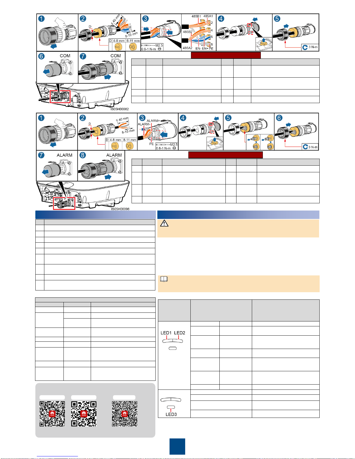
COM Port Pin Definitions
ALARM Port Pin Definition
4 Verifying the Installation
1. Turn on the AC switch between the SUN2000L and the power grid.
2. Turn on the DC switch between the PV string and the SUN2000L if there is any.
3. Turn on the DC switch at the bottom of the SUN2000L.
4. If a battery connects to the battery terminals, turn on the power switch on the battery, and
then turn on the battery switch.
5. Perform quicksetting overthe app by referring to the SUN2000LAppQuickGuide.
6. (Optional) Measure the temperatures at the joints between the DC terminals and the
connectors using a point-test thermometer.
7. Observe the LEDs to check the SUN2000L operating status.
Before turning on the AC switch between the SUN2000L and the power grid, check that
the AC voltage on the power grid side of the AC switch is within the specified range.
5 Powering On the System
Scan here for more
documents:
Scan here for Huawei
technical support:
iOS Android
You can also log in to Huawei technical support
website: http://support.huawei.com
Huawei Technologies Co., Ltd.
Huawei Industrial Base, Bantian, Longgang
Shenzhen 518129 People's Republic of China
www.huawei.com
NOTICE
Type
Status (Blinking at Long
Intervals: On for 1s and then Off
for 1s; Blinking at Short
Intervals: On for 0.2s and then
Off for 0.2s)
Meaning
Running
indication
LED1
LED2
N/A
Steady green
Steady green
The SUN2000L is
exporting power to the power grid.
Blinking green
at long
intervals
Off
The DC is on and the AC is off.
Off
Blinking green at
long intervals
The DC is off and the AC is on.
Blinking green
at long
intervals
Blinking green at
long intervals
Both the DC and AC are on, and the
SUN2000L is not exporting power to
the power grid.
Off
Off
Both the DC and AC are off, or the
SUN2000L is in low power
consumption mode.
Steady red
Steady red
The SUN2000L is faulty.
Communication
indication
LED3
N/A
Blinking green at short intervals
The SUN2000L is in communication.
Blinking green at long intervals
The SUN2000L has connected to the
mobile phone.
Off
Others
No.
Label
Definition
No.
Label
Definition
1
ALARM–
Alarm signal–
2
ALARM+
Alarm signal+
3
485B3
RS485B, RS485 differential
signal–(reserved)
4
485A3
RS485B, RS485 differential
signal–(reserved)
5
12V–
Negative of the 12 V power
supply (reserved, power ≤ 3 W)
6
12V+
Positive of the 12 V power
supply (reserved, power ≤ 3 W)
7
N/A
N/A
8
PE
Grounding the shield layer
No.
Label
Definition
No.
Label
Definition
1
485B1
RS485B, RS485 differential
signal–
2
485A1
RS485A, RS485 differential
signal+
3
485B2
RS485B, RS485 differential
signal–
4
485A2
RS485A, RS485 differential
signal+
5
EN–
Enable signal–
6
EN+
Enable signal+
7
N/A
N/A
8
PE
Grounding the shield layer
Under normal operation conditions of the SUN2000L, the temperature rise at DC
connectors should remain below 30°C at all time.
NOTE
No.
Acceptance Criteria
1
The SUN2000L is installed correctly and securely.
2
The WiFi antenna is installed correctly and securely.
3
Cables are routed properly as required by the customer.
4
Cable ties are secured evenly and no burr exists.
5
The ground cable is connected correctly and securely.
6
The DC switch and all the switches connecting to the SUN2000L
are OFF.
7
The AC output power cable, DC input power cable, battery
cable, and signal cable are connected correctly and securely.
8
Unused terminals and ports are locked by watertight caps.
9
The installation space is proper, and the installation environment
is clean and tidy, without foreign matter.
Support
Customer Service Contact Information
Region
Country
Service Support Mailbox
Europe
All countries
eu_inverter_su[email protected]
Asia Pacific
Australia
au_inverter_su[email protected]
Other
countries
MYEnte[email protected]
Japan and
Korea
Japan and
Korea
[email protected]
China
China
solarservice@huawei.com
India
India
in_inverter_sup[email protected]
North America
The United
States and
Canada
na_inverter_su[email protected]
Latin America
All countries
la_inverter_sup[email protected]
The Middle
East and
Africa
All countries
mea_inverter_support@huawei.com

Other manuals for SUN2000L-2KTL

2

This manual suits for next models

1

Other Huawei Inverter manuals

Huawei SUN2000-125KTL-JPH0 User manual

Huawei

Huawei SUN2000-125KTL-JPH0 User manual

Huawei iSitePower-M V100R002C00 User manual

Huawei

Huawei iSitePower-M V100R002C00 User manual

Huawei SUN2000-3.8KTL-USL0 User manual

Huawei

Huawei SUN2000-3.8KTL-USL0 User manual

Huawei MERC Series User manual

Huawei

Huawei MERC Series User manual

Huawei SUN2000-3KTL-10KTL-M0 User manual

Huawei

Huawei SUN2000-3KTL-10KTL-M0 User manual

Huawei SUN2000-63KTL-JPH0 User manual

Huawei

Huawei SUN2000-63KTL-JPH0 User manual

Huawei SUN2000-50KTL-JPM0 User manual

Huawei

Huawei SUN2000-50KTL-JPM0 User manual

Huawei SUN2000-43KTL-IN-C1 User manual

Huawei

Huawei SUN2000-43KTL-IN-C1 User manual

Huawei SUN2000L-5KTL User manual

Huawei

Huawei SUN2000L-5KTL User manual

Huawei SUN2000-50KTL-M0 User manual

Huawei

Huawei SUN2000-50KTL-M0 User manual

Huawei SUN2000-4.95KTL-NHL2 User manual

Huawei

Huawei SUN2000-4.95KTL-NHL2 User manual

Huawei SUN2000-8KTL-M0 User manual

Huawei

Huawei SUN2000-8KTL-M0 User manual

Huawei SUN2000 Series User manual

Huawei

Huawei SUN2000 Series User manual

Huawei SUN2000-100KTL User manual

Huawei

Huawei SUN2000-100KTL User manual

Huawei SUN2000L Series User manual

Huawei

Huawei SUN2000L Series User manual

Huawei SUN2000 MB0 Series User manual

Huawei

Huawei SUN2000 MB0 Series User manual

Huawei SUN2000 Series User manual

Huawei

Huawei SUN2000 Series User manual

Huawei EMMA-A01 User manual

Huawei

Huawei EMMA-A01 User manual

Huawei SUN2000 Series User manual

Huawei

Huawei SUN2000 Series User manual

Huawei 01075345 User manual

Huawei

Huawei 01075345 User manual

Huawei SUN2000-33KTL-A User manual

Huawei

Huawei SUN2000-33KTL-A User manual

Huawei SUN2000-375W-USP0 User manual

Huawei

Huawei SUN2000-375W-USP0 User manual

Huawei SUN2000-90KTL User manual

Huawei

Huawei SUN2000-90KTL User manual

Huawei SUN2000 Series User manual

Huawei

Huawei SUN2000 Series User manual

Popular Inverter manuals by other brands

Astronergy CHSM5409M installation guide

Astronergy

Astronergy CHSM5409M installation guide

TGS WP-EWG-040U Installation and operation instructions

TGS

TGS WP-EWG-040U Installation and operation instructions

Hitachi SJ100 Series Supplemental sheet

Hitachi

Hitachi SJ100 Series Supplemental sheet

LS Industrial Systems SV-iV5 Series user manual

LS Industrial Systems

LS Industrial Systems SV-iV5 Series user manual

Conrad GW-INSTEK AFG-2225 operating instructions

Conrad

Conrad GW-INSTEK AFG-2225 operating instructions

Argo CHARM DUAL 9000 UI User manual and installation guide

Argo

Argo CHARM DUAL 9000 UI User manual and installation guide

NewArc Mig500 Operational manual

NewArc

NewArc Mig500 Operational manual

EE Systems Group eLEDing EE828WAI-2H quick start guide

EE Systems Group

EE Systems Group eLEDing EE828WAI-2H quick start guide

Certa CTSIWAVINVB user guide

Certa

Certa CTSIWAVINVB user guide

Growatt SPH-UP Series installation manual

Growatt

Growatt SPH-UP Series installation manual

Offroad Living AllSpark PS Series user manual

Offroad Living

Offroad Living AllSpark PS Series user manual

Shindaiwa DG450UMI-QD user manual

Shindaiwa

Shindaiwa DG450UMI-QD user manual

Siel SOLEIL 3F-TL10K Installation and operation manual

Siel

Siel SOLEIL 3F-TL10K Installation and operation manual

Victron energy EasySolar 12/1600/70 manual

Victron energy

Victron energy EasySolar 12/1600/70 manual

Clarke CI-600 User instructions

Clarke

Clarke CI-600 User instructions

YASKAWA VS MINI J7 series instruction manual

YASKAWA

YASKAWA VS MINI J7 series instruction manual

Stanley E-SG 2200 Original instructions

Stanley

Stanley E-SG 2200 Original instructions

Sinclair SDV4-140HB3P user manual

Sinclair

Sinclair SDV4-140HB3P user manual

manuals.online logo
manuals.online logoBrands
  • About & Mission
  • Contact us
  • Privacy Policy
  • Terms and Conditions

Copyright 2025 Manuals.Online. All Rights Reserved.