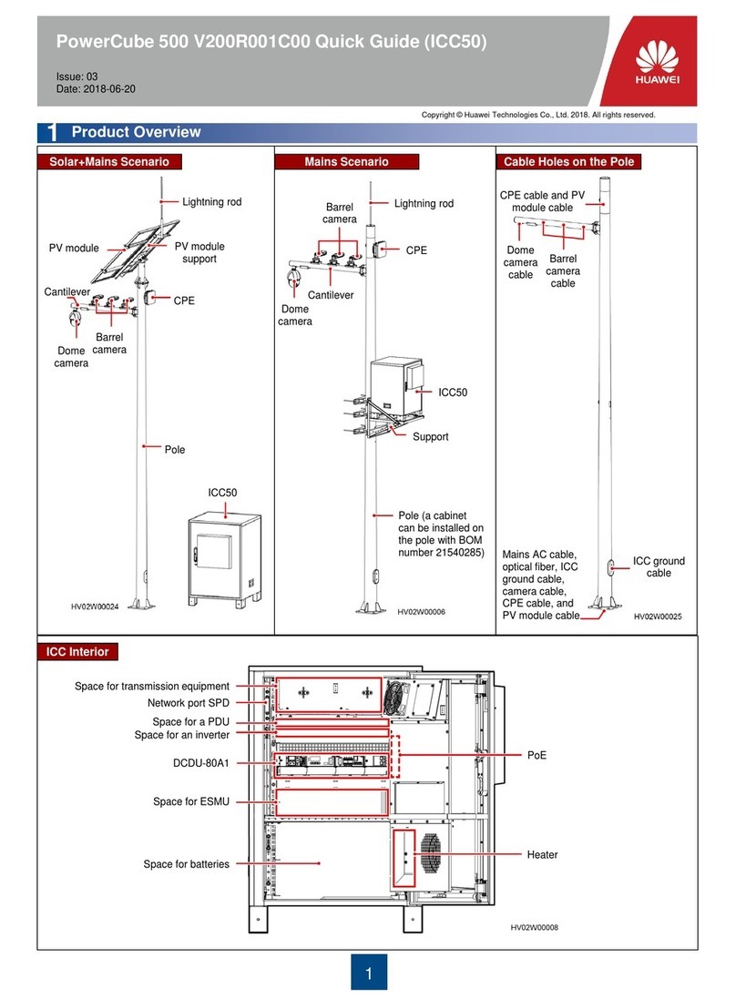
3
Click
Click
1. Connect the AC output power cable to
the AC connector.
2. Connect the AC connector to the AC output port.
Installing the DC Input Power Cable
3.4
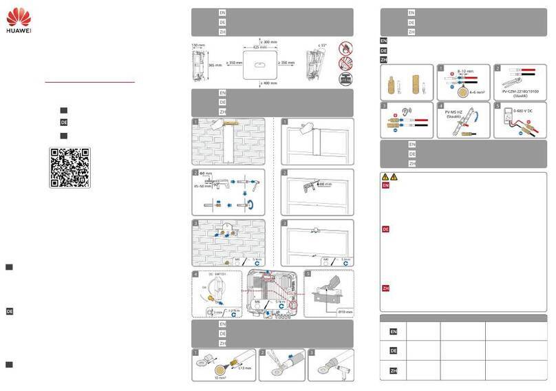
1. Ensure that the PV module output is well insulatedto ground.
2. The SUN2000LDC input voltage must always be lower than or equal to 600 V DC.
3. Before installing the DC input power cable, label the cable polarities correctly to ensure
correct cable connections.
4. Use the positive and negative metal terminalsand black DC connectorssuppliedwith the
SUN2000L.Using other modelsof positive and negative metal terminalsand DC
connectors may result in serious consequences. The caused device damage is not
covered under any warranty or service agreement.
5. If polarity of the DC input power cable is reversedand the DC switch is ON, do not turn
off the DC switch immediatelyor unplug positive and negative connectors.The device
may be damagedif you do not follow the instruction. This damage is not covered under
any warranty or service agreement. Wait until the solar irradiance declines at night and
the PV string current reduces to below 0.5 A, and then turn off the DC switch and remove
the positive and negative connectors. Correct the string polarity before reconnectingthe
string to the SUN2000L.
Positive connector
Negative connector
Positive metal terminal
Negative metal terminal Ensure that the cable will not
be extracted after crimped.
Ensure that
the locking nut
is secured.
Ensure that the
cables are correctly
connected.
3. Check the route of the AC
output power cable.
Three-Core Cable (L, N, and PE)
Two-Core Cable (L and N)
Pull the DC input power cable
back to ensure that it is
connected securely.
Pull the DC input power cable
back to ensure that it is
connected securely.
Click
When laying out signal cables, separate them from power cables to avoid strong signal interference sources.
The protection layer of the signal cable is in the connector. Surplus core wires are cut off from the protection layer. The exposed core wire
is totally inserted into the cable hole and connected securely.
Do not confuse the connector to the COM port and the connector to the ALARM port.
If a connector needs to connect to only one signal cable, block the unused cable hole in the seal using a cap and tighten the cable gland.
If a connector needs to connect to two signal cables, ensure that the cables have the same outer diameter.
(Optional) Installing the Signal Cable
3.6
To remove the AC connector from the SUN2000L, perform the operations in reverse order.
The right figure shows how to remove a plug insert.
The battery voltage will result in fatal injury. Use dedicated
insulation tools to terminate cables.
Ensure that the battery cable is correctly connected. Avoid
reverse polarity.
Assemble the blue positive and negative connectors by following the instructions in section 3.4 "Installing the DC Input Power Cable."
Pull the battery cable back to ensure
that it is connected securely.
Click
Save the
watertight caps for
later use.
(Optional) Installing the Battery Cable
3.5

