1. Ensure the LED load's rated power is greater than or equal to the power output of this emergency LED driver (9W). This is to ensure that this emergency product will not
produce more power than the LED load can handle, thus ensuring that the LED load will not be damaged when the system is in the emergency mode.
2. Verify the forward voltage of the luminaire's LED array is within the limits of this emergency LED driver. The forward voltage of the LED array is commonly designated as Vf
and should be found on the luminaires markings, in the luminaire specications, or imprinted directly on the LED arrays. If multiple LED arrays are to be driven, verify that
the total forward voltage is within the limits of this product. Using a voltage meter, it may be possible to directly measure the voltage across the LED array when operating
from the AC driver.
3. Ensure the output current of the LED driver does not exceed 1.6 Amps. This is the current into the blue wire.
4. Ensure the LED xture’s rated efcacy is equal to or greater than 65 lm / watt. This is to ensure that the LED xture can be mounted at or below the maximum rated mounting
height of 28.4ft.
5. Ensure there will be sufcient light output in the end application. Estimate the emergency egress lighting illumination levels by doing the following:
a. Find the efcacy of the LED lighting xture, Luminaire efcacy information can be found at the Design Lights Consortium website (http://www.designlights.org), Energy
Star - Certied Products - product nder website (http://www.energystar.gov/productnder) or given by the luminaire manufacturer on product catalog specication
sheets. The LED xture efcacy will be given in lumens per watt (lm/w).
b. Lumens can be calculated by multiplying the output power of the emergency LED driver (9W) by the efcacy of the LED load.
In many cases the actual lumen output in emergency mode will be greater than this calculation gives, however it will provide a good estimate for beginning the lighting
design of the system.
Lumens In Emergency Mode = Lumens Per Watt of Fixture * Output Power of Chosen Product
(LUMENS) = (LM/W) * W
c. Using the results of this calculation and industry standard lighting design tools, calculate the anticipated illumination levels in the path of egress.
CAUTION: SUPPLY AC POWER TO THE EMERGENCY DRIVER BEFORE JOINING EITHER
CONVERTER CONNECTOR RED WIRES
INSTALLATION
This product is suitable for field installation with suitable LED loads including LED luminaires, DC voltage driven LED
replacements for fluorescent lamps and others. There are 4 checks to determine if your luminaire is eligible for use with this
LED battery pack.
NOTE: This product has been designed to reliably interface with a wide selection of LED loads and is electrically
compatible with every simple LED array that meets criteria 1 - 4 above. However, compatibility cannot be
guaranteed with all current and future LED systems. Compatibility testing of the end-use system is suggested.
Please contact the factory with any questions.
NOTE: After installation, it will be necessary to measure the egress lighting illumination levels to ensure it
complies with national, state and local code requirements.
Installation of this Emergency LED Driver will vary based on the luminaire type, however, generally follow these steps.
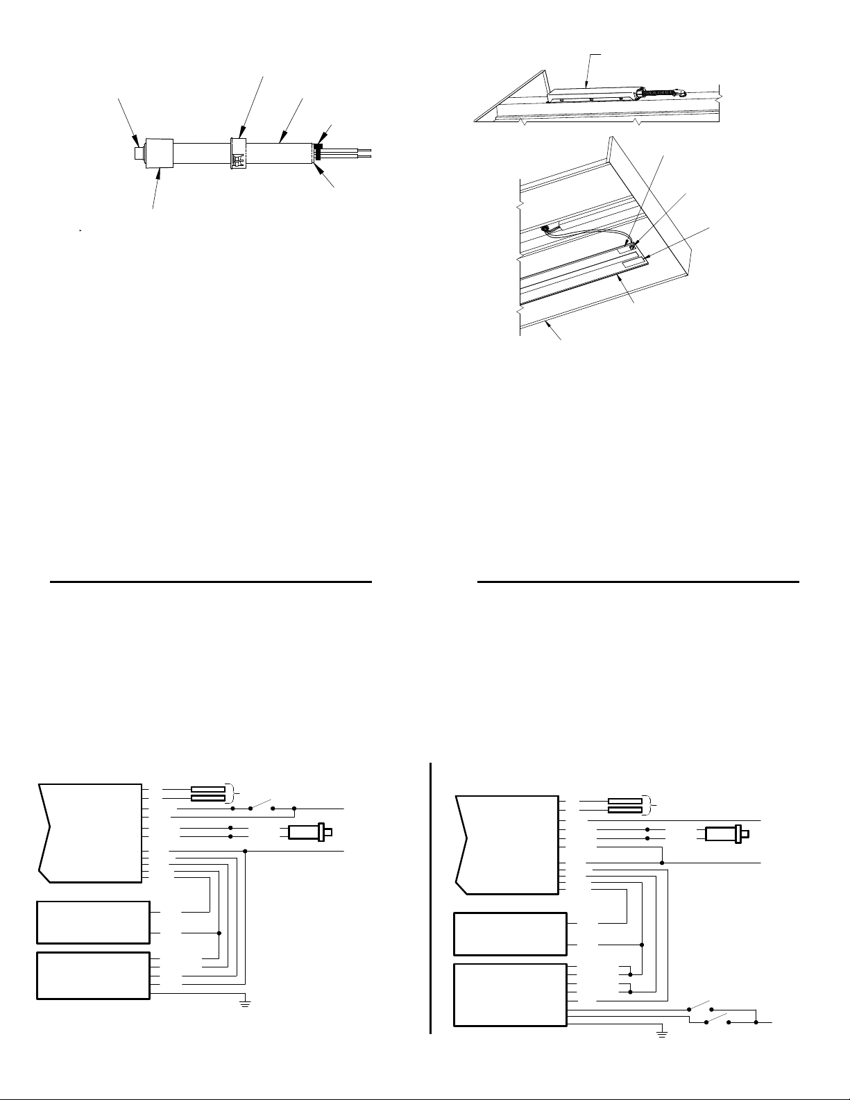
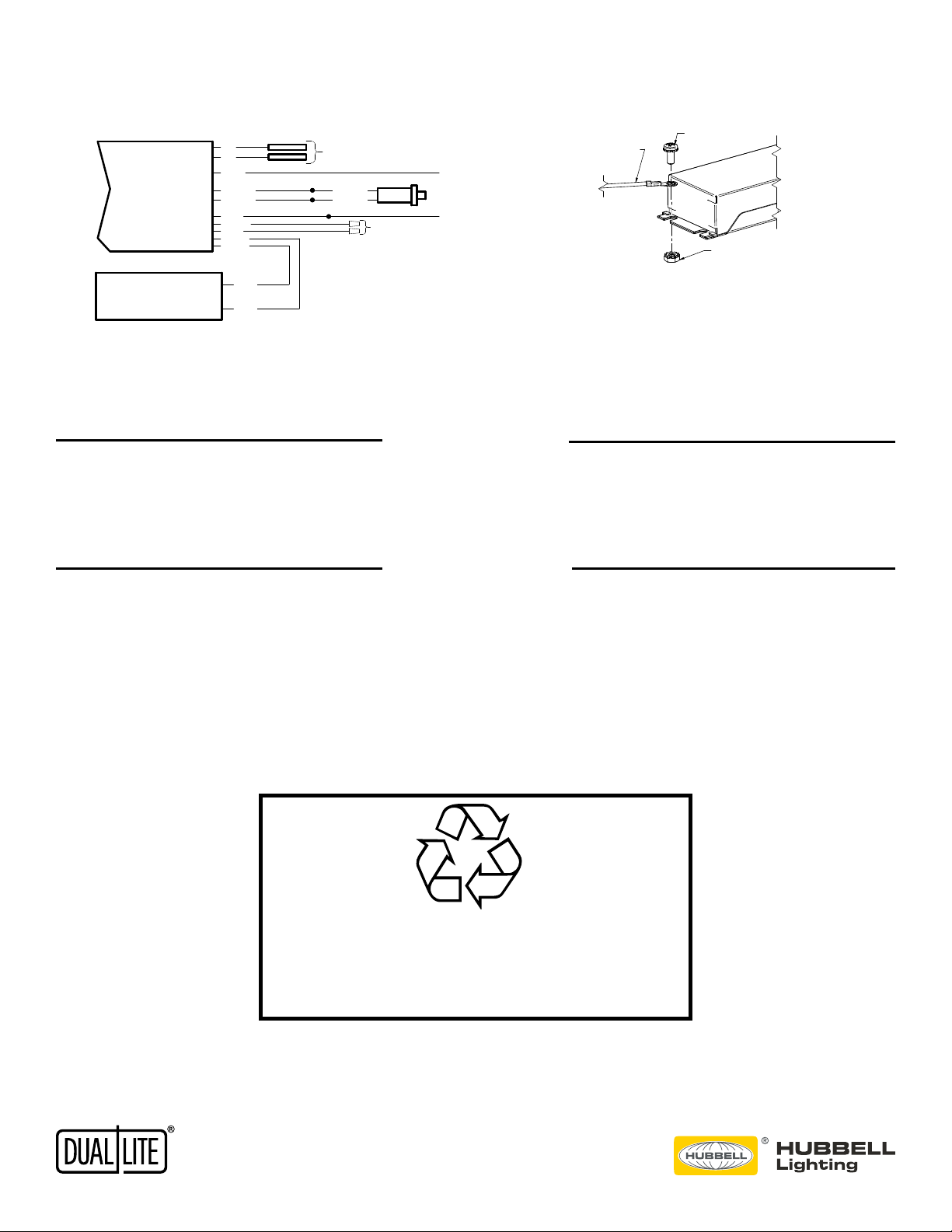
Step 1. Disconnect AC power to the LED lighting xture. Remove lens and ballast channel cover from LED xture if applicable. (see illustrations 2 & 4)
Step 2. Using the 2 supplied screws, mount the LED emergency driver.
The lighting xture instructions might provide suggestions on the driver mounting location.
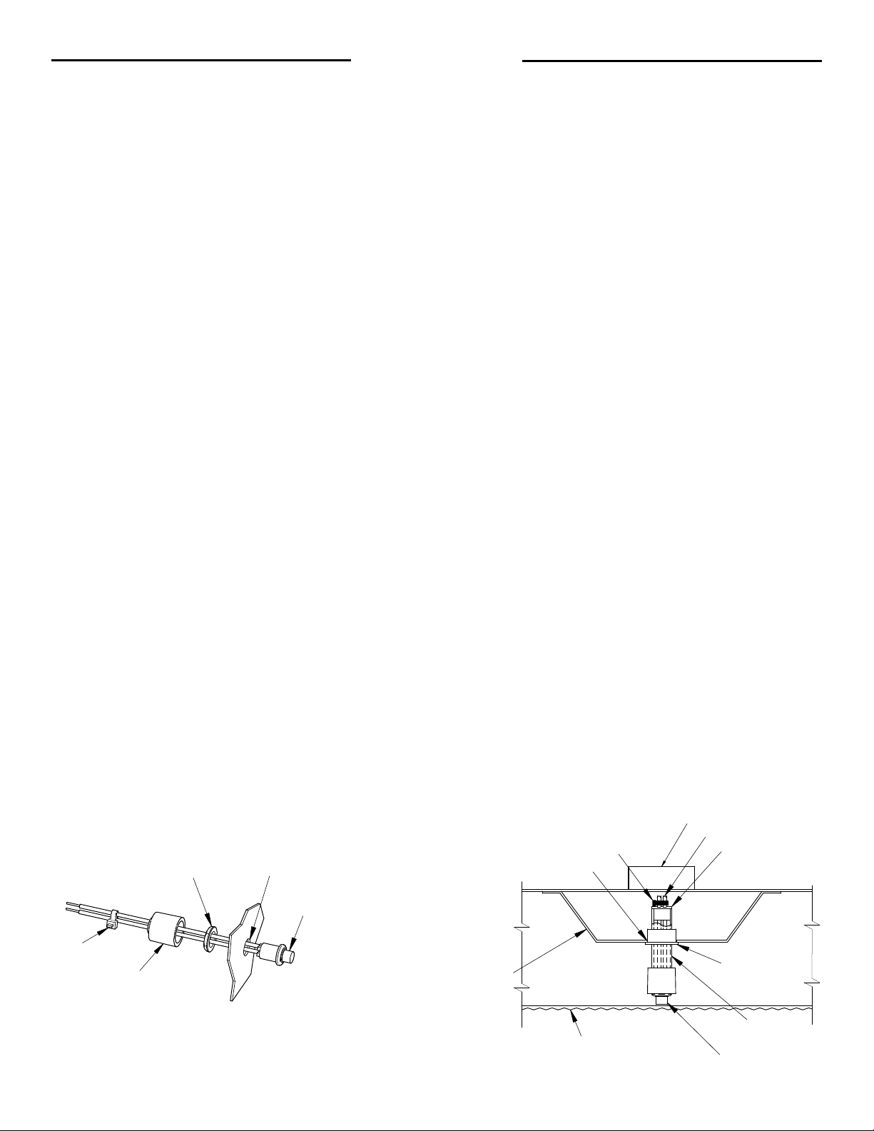
Step 3. Test switch/indicator light can be mounted directly to a xture surface thru a 1/2 inch diameter hole. Once nut is tightened, slip UL switch cover over wires,
pushing cover against xture surface completely covering switch, then afx ty-wrap over wires against cover to secure. Switch should be visible once xture is installed.
(see illustration 1 & 4)
Step 4. Test switch/indicator light can also be installed onto a driver channel cover through a 7/8 inch diameter hole (see illustrations 2 & 3.) Trim plastic tube to desired length,
afx UL switch cover as shown and place into tube. Afx both the small bushing and the large bushing onto the plastic tube as shown. Connect tie wrap onto wires,
tighten and insert into channel. Switch should be visible once xture is installed.
1/2" DIA.
THRU HOLE
SUPPLIED NUT
SUPPLIED TEST SWITCH/
INDICATOR LIGHT
TY-WRAP
SW INDICATOR
LARGE
BUSHING
PLASTIC
TUBE
SW INDICATOR
PLASTIC
TUBE
LARGE
BUSHING
EM DRIVER
SMALL
BUSHING
SW LEADS
TIE WRAP
7/8" DIA THRU
HOLE
BALLAST
CHANNEL
COVER
FIXTURE
DIFFUSER
LENS
93071446
ILLUSTRATION 2
ILLUSTRATION 1
93071446
TY-WRAP
UL SWITCH
COVER
ALBALBEC-1612120095/22/171
4 3
D
C
B
A
4 3
2 1
D
C
B
A
12
REV DATE RECORD DESN CHCK
SHT 1
1 SHTS
--- ---
93084715
93084715
1
ILL-TEST SW ILL 2 PLD10M
ALB 05/22/17
ALB 5/22/17
---
ALB 5/22/17
NTS
REV.DRAWING NO.SIZESCALE
PART NO.FINISH:MATERIAL:
This document contains confidential and proprietary information of Dual
Lite. Receipt or possession of this document does not convey any rights to
reproduce or disclose its contents, or to make, use , or sell anything it may
disclose. Reproduction, disclosure, or use of the document or its contents,
without the specific written authorization of Dual Lite, may violate the
intellectual property rights of Dual Lite.
DIMENSIONS IN INCHES
DIMENSIONS IN [ ] IN MM
CONFORMS TO ASME Y14.5M
DO NOT SCALE PRINT
DRAWN BY:
THIRD ANGLE PROJECTION
CHECKED BY:
ENGINEERING:
CATALOG NO.
CRITICAL DIMENSIONS
C
UNSPECIFIED TOLERANCES: INCHES
X.XX=
u
0.12
FRACTIONS=
u
1/32 ANGULAR TOLERANCE=
u
1
v
THIS ILL IS ON INSTRUCTION SHEET 93078192
SW INDICATOR
PLASTIC
TUBE
LARGE
BUSHING
SMALL
BUSHING
SW LEADS
TIE WRAP
7/8" DIA THRU
HOLE
BALLAST
CHANNEL
COVER
FIXTURE
DIFFUSER
LENS
93084715