Hubbell CR Operating instructions

OPERATING AND MAINTENANCE MANUAL FOR
INSTANTANEOUS ELECTRIC
CIRCULATION HEATER
ELECTRIC HEATER COMPANY
BASE MODEL “ CR ”

2
HUBBELL
ELECTRIC HEATER COMPANY
P.O. BOX 288
STRATFORD, CT 06615
PHONE: (203) 378-2659
FAX: (203) 378-3593
INTERNET: http://www.hubbellheaters.com/
-- IMPORTANT --
Always reference the full model number and serial number when calling the factory.
WARNING / CAUTION
1. Tank is to be completely filled with water and all air is to be vented before energizing.
2. Due to the rigors of transportation, all connections should be checked for tightness before
heater is placed in operation.
3. Safety relief valve must be installed in tapping provided.
4. The refractory material used in heating elements may absorb some moisture during
transit, periods of storage, or when subjected to a humid environment. This moisture
absorption results in a cold insulation resistance of less than twenty (20) megohms. If this
heater has been subjected to the above condition, each heating element must be checked
for insulation resistance before energizing. A low megohm condition can be corrected by
removing the terminalhardware and baking the element in an oven at 350°F -700°F for
several hours or until the proper megohm reading is obtained.
5. KEEP AWAY FROM LIVE ELECTRICAL CIRCUITS.
Do not perform any maintenance, make any adjustments, or replace any components
inside the control panel with the high voltage power supply turned on. Under certain
circumstances, dangerous potentials may exist even when the power supply is off. To
avoid casualties, always turn the power supply safety switch to off, turn the charge or
ground the circuit before performing any maintenance or adjustment procedure.
6. The unit is designed to operate at pressure not more than 150 psi.
7. Generalized instructions and procedures cannot anticipate all situations. For this reason,
only qualified installers should perform the installations. A qualified installer is a person
who has licensed training and a working knowledge of the applicable codes regulation,
tools, equipment, and methods necessary for safe installation of an electric resistance
water heater. If questions regarding installation arise, check your local plumbing and
electrical inspectors for proper procedures and codes. If you cannot obtain the required
information, contact the company.

SECTION TITLE PAGE No.
I GENERAL DESCRIPTION AND CONSTRUCTION 4
II INSTALLATION AND START-UP 7
III SCHEDULED MAINTENANCE AND OPERATION 9
IV TROUBLESHOOTING 10
V SERVICING AND REPLACEMENT OF PARTS 12
VI MISCELLANEOUS CHARTS AND FORMULAS 16
3

4
SECTION I - GENERAL DESCRIPTION AND CONSTRUCTION
GENERAL DESCRIPTION
This book describes a packaged electric heater that is a stationary, self-contained unit. The
complete assembly consists of the pressure vessel, immersion electric heating element,
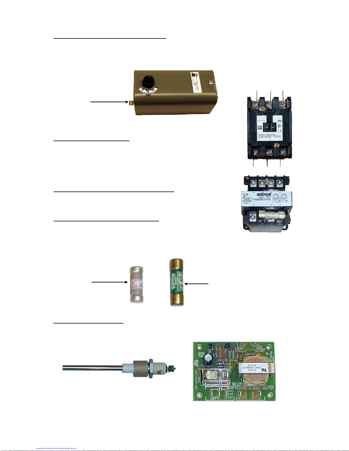
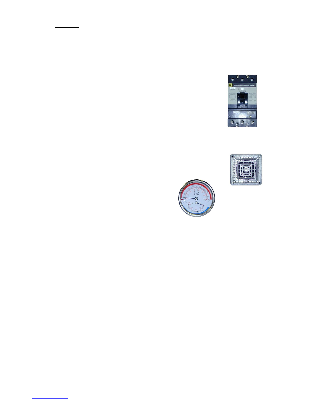
thermostat, safety relief valve, safety high temperature cut out, magnetic contactor(s), power
circuit fusing, fused low voltage control circuit transformer, and any other required electrical
operating control. Optional equipment may be supplied with your unit. Please consult the
product drawing for details specific to your assembly. The unit is factory assembled, insulated,
jacketed, wired, tested, and ready for electrical and plumbing service connections.
CONSTRUCTION
PRESSURE VESSEL
Standard Vessel Construction:
The standard pressure vessel is constructed of all welded carbon steel, then hot dip galvanized
for added corrosion resistance. Units over 58 kW are designed and built in accordance with
ASME Section IV and stamped, certified, and registered with the National Board of Boiler and
Pressure Vessel Inspectors. The maximum allowable working pressure is stamped on the
nameplate. The standard working pressure is 150 psi (225 psi TP).
Optional Non-Ferrous Vessel Materials:
1. Copper-Silicon – A copper-silicon alloy offers tremendous longevity due to its ability to
withstand the cycling effects induced from changes in water temperature and pressure.
This material is suitable for storage of hot potable water in a variety of commercial and
industrial applications.
2. 90/10 Copper-Nickel – A 90% copper and 10% nickel alloy similar to copper-silicon, but
with added strength and corrosion resistance. Typically used in applications with
corrosive environments (salt water) or critical applications.
3. Stainless Steel – Stainless steel (type 304, 316, or 316L) is well suited for high purity
applications requiring a corrosion resistant tank with minimal leaching of impurities into
the water. Well suited for process, RO, and DI water systems in the pharmaceutical, food,
and electronic industries.
4. Other materials are available upon request.
Optional Working Pressures:
The pressure vessel may be supplied with optional working pressures (standard working
pressure is 150 psi). See drawing for details.
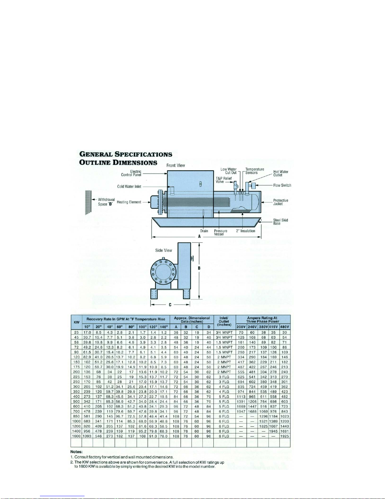
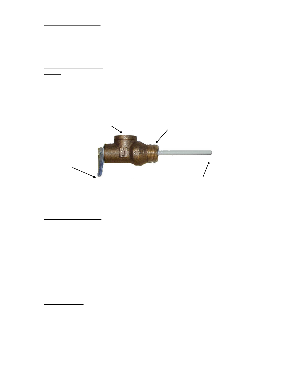
VESSEL CONNECTIONS
The heater is supplied with separate cold water and hot water connections. A connection is
provided for mounting a combination safety temperature and pressure relief valve. An overflow
line should be utilized from the relief valve outlet to a floor drain. See drawing for locations and
sizes.
OUTER SHELL, INSULATION, AND SUPPORTS
The pressure vessel is encapsulated in 2-inches of high-density fiberglass insulation. The
protective shell is constructed of galvaneel and is coated with a durable silver hammertone
finish. The horizontal configuration is supported on heavy-duty steel I-beam supports. Also
available in a vertical configuration or wall hung for off the floor installation.
HEATING ELEMENT
The heater is supplied with a flanged electric immersion heating element assembly, composed
of copper, incoloy, or stainless steel sheathed elements that are brazed or welded into a ANSI
steel flange. The heating element is fastened to a corresponding tank flange using a gasket and
hex head steel bolts and nuts. Specialized heating element construction may be included. These
options include: special watt density ratings, passivation, electropolishing, or special materials.
See drawing for voltage, power ratings, and special options.

ELECTRICAL ENCLOSURE
A louvered control panel available in various sizes and
with assorted types of handles is supplied. The standard
cabinet is rated NEMA 1, but other NEMA rated
enclosures are available, consult drawing for further
information. A list of NEMA ratings are available in
Section VI. An optional explosion-proof enclosure is available for
hazardous locations.
5
FLOW SWITCH
The heater is supplied with a factory installed and wired safety flow
switch. This device will allow the immersion heating element to
energize only when there is sufficient flow through the unit.
CONTROL THERMOSTAT
The control panel is supplied standard with a single-stage immersion
thermostatic switch. As an optional any of the following may be
supplied; a four-stage immersion thermostatic switch, a solid-state staging controller with
thermistor, or a digital 1/16 DIN temperature controller with thermocouple. See drawing for
specific details. The single-stage immersion thermostat can be adjusted through a range of 100°
- 190° F. A low range, (30° - 110° F), operating thermostat is also available in the single-stage
version. The four-stage immersion thermostat can be adjusted through a range of 100° - 250° F
and is capable of switching four circuits. The solid-state staging controller automatically brings
on-line the required number of heating steps in order to meet the hot water demand and will
also operate each circuit in a circular mode to allow for equal usage of all heating circuits. The
thermostat is adjustable to the desired temperature by turning the dial on the pot switch. A 1/16
DIN electronic temperature control package may be installed. A separate manufacturer’s
operating manual will be supplied with all units except the single-stage immersion thermostat.
Single-StageImmersionThermostat
Four-Stage Immersion Thermostat
1/16DINDigitalDisplay Solid State Staging Controller

TEMPERATURE HIGH LIMIT SWITCH
As a safety device, an immersion high temperature cut-off switch with manual reset, adjustable
through a range of 100° - 240° F, is provided. The high limit must be manually reset thereafter
to restart the heater. Optionally a 1/16 DIN digital controller may be used as a high-limit.
6
Manual Reset
MAGNETIC CONTACTOR
The magnetic contactor(s) is a heavy-duty resistive load type rated for
100,000 cycles. The contactor supplies power to the heating element(s)
based on the resistive load (non-inductive) of the heater only when the
thermostatic switch is engaged, thereby pulling in the contacts until the
desired temperature is reached. At this point, the contacts will drop out,
which in turn disconnects power from the elements.
FUSED LOW VOLTAGE TRANSFORMER
A fused low voltage transformer may be supplied. This option is used to
step down higher voltages to 120-volt for safety when working with
control circuits.
INDIVIDUALLY FUSED ELEMENTS
To prevent the possibility of damage to control circuits and other elements
in case of electrical overloads, fuses may be supplied for each element.
Two types of fuses may be used; a type NON for voltages less than 250-volt or type JJS for
voltage less than 600-volt.
Type JJS Type NON
LOW WATER CUT-OFF
Used as a safety device, the electronic low water cut-off is used to detect a low water situation
and disengage the operating coils in the magnetic contactor(s). Once the condition is remedied,
the low water cut-off switch is automatically reset.
Conductive Type Low Water Cut-Off Relay

OPTIONS
The following optional features may be included in your water heater. Reference included
drawing specific to your heater for further details.
Stainless Steel Jacket
An optional stainless steel outer jacket may replace the standard galvaneel covering. This
optional jacket may be painted.
On / Off Control Switch
A built-in non-fused On/Off disconnect switch may be supplied with the control panel to
decrease the risk of injury when working with the control panel.
Built-In Circuit Breaker
A built-in circuit breaker may be provided with or without shunt trip
protection for protection from circuit overload.
Audible Alarm
An audible alarm may be installed on the outside of the control panel to give
warning of an over-temperature condition.
Building Management System (BMS)
A Building Management System control package may be supplied for remote
operation and alarm capabilities.
Status Indicating Lamp(s)
Optional status indicating lamps may be installed to show when the unit is on, when the
heating element is energized, or if there is an alarm condition.Silicon
Control Rectifier
An SCR “zero fired” power controller for 0-100% proportional control of
heaters may be supplied.
Dial Temperature and Pressure Gauge
A combination temperature (70° - 250° F) and pressure
(0 – 200 psi) gauge with 2½-inch dial may be supplied
for in-line installation (shipped loose) or factory
installed in the tank.
Special Customized Features
Please reference drawing for details.
SECTION II –INSTALLATION
WARNING / CAUTION
DO NOT TURN ON THE ELECTRIC POWER SUPPLY to this equipment until heater is
completely filled with water and all air has been released. If the heater is NOT filled with
water when the power is turned on, the heating elements will burn out.
For protection against excessive pressures and temperatures, local codes require the
installation of a temperature-and-pressure (T&P) relief valve certified by a nationally
recognized laboratory that maintains periodic inspection of production of listed equipment of
materials, as meeting the requirements for Relief Valves and Automatic Gas Shutoff for Hot
Water Supply Systems. ANSI Z21.22-1971. THE CUSTOMER IS RESPONSIBLE TO
PROTECT PROPERTY AND PERSONNEL FROM HARM WHEN THE VALVE
FUNCTIONS.
All water heaters have a risk of leakage at some unpredictable time. IT IS THE
CUSTOMER'S RESPONSIBILITY TO PROVIDE A CATCH PAN OR OTHER
ADEQUATE MEANS, SO THAT THE RESULTANT FLOW OF WATER WILL NOT
DAMAGE FURNISHINGS OR PROPERTY.
7

HEATER PLACEMENT
1. Place the heater on a solid foundation in a clean, dry location nearest to the point of
most frequent hot water use.
2. The heater should be protected from freezing and waterlines insulated to reduce
energy and water waste.
3. Leave sufficient clearance for element withdrawal, if necessary.
4. Do not install in an area where flammable liquids or combustible vapors are present.
PIPING INSTALLATION
NOTE: The most effective means for preventing deterioration from accelerated corrosion
due to galvanic and stray current is the installation of dielectric fittings/unions. The
installation of these fittings is the responsibility of the installing contractor.
1. Connect the cold water inlet and hot water outlet to the appropriate connections as
shown; refer to the drawing for location and sizes.
2. Install in-line vacuum breaker and in-line pressure and temperature gauge, if supplied.
3. Install the combination temperature and pressure safety relief valve in the tapping
provided. Note that this is required by law for safety considerations.
Outlettofloordrain Installintoprovidedtapping
Manual Release
Lever
Temperature and Pressure Relief Valve
Temperature ProbeTemperature Probe
4. Install a relief valve overflow pipe to a nearby floor drain. CAUTION: No valve of
any type should be installed between the relief valve and tank or in the drain line.
FILLING THE HEATER
1. Completely close the drain valve and open the highest hot water valve to allow all air
to escape from piping.
2. Open the valve to the cold water inlet and allow the heater and piping system to
completely fill, as indicated by a steady flow of water from the open faucet.
ELECTRICAL INSTALLATION
1. Enter electric enclosure with properly sized feeder leads (use 60° C copper wire for
water heaters rated less than 100 amps; otherwise use 75°C copper wire). Single-phase
installations require two (2) leads; three phase installations require three (3) leads.
2. Install these power leads into the box lugs on the terminal block or magnetic
contactor.
3. Torque screws per torque chart included in Section VI.
4. All other electrical connections are made at the factory; therefore, no other electrical
connections are necessary.
FINAL CHECKS
1. Check all connections for tightness.
2. Ensure that all the above steps are completed.
3. After the water is heated for the first time, monitor the water temperature as described
in Section III, Quarterly Inspection.
8

9
SECTION III -SCHEDULED MAINTENANCE AND OPERATION
WARNING / CAUTION
Before performing any maintenance procedure,make certain power supply is OFF and
cannot accidentally be turned on.
MAINTENANCE AND OPERATION
The heater is automatic in its operation. It will maintain water at the temperature setting of
the thermostat. The heater should not be turned on without first making sure that the vessel is
full of water and that all air has been released.
FREEZING
The vessel should be fully drained in the event the electricity has been turned off and if there
is danger of freezing.
QUARTERLY INSPECTION
1. Monitor thermostat
a. Let water heater completely heat to a designated thermostat setting.
b. After thermostat satisfies (that is, when the thermostat actually clicks off), draw water
from heater.
c. Compare water temperature of drawn water to the temperature setting of the
thermostat when it satisfies. Normal variation between the two points is
approximately + 5°F.
d. If these two readings do not coincide within acceptable tolerances and verification has
been made of the accuracy of the temperature-reading gauge, replace the thermostat.
2. Lift test lever on relief valve and let water run through valve for a period of
approximately 10 seconds. This will help flush away any sediment that might build up in
water passageways.
3. Inspect element flange for leakage as follows:
a. Shut off Power Supply.
b. Remove element housing cover.
c. Visually inspect heating element gasket for evidence of leaks.
d. Rub finger around gasket that is between the heating element and tank flange for any
evidence of moisture. If moisture is present or a water drip is observed, follow
procedure outlined in Section V.
4. Check for loose electrical connections. Tighten as necessary.

10
SECTION IV –TROUBLESHOOTING
Symptom Probable Cause Corrective Action / Remedy
No hot water Circuit breaker tripped at
source. Reset circuit breaker.
On/Off switch in ‘OFF’
position, if installed. Turn switch to ‘ON’ position.
Circuit breaker at control
cabinet tripped, if installed. Reset circuit breaker.
Blown fuse in element fuse
block, if installed. Replace fuse.
Blown fuse in transformer,
if installed. Replace fuse.
High limit switch tripped. Reset high limit switch.
Loose wires. Tighten wires. Torque screws
per torque chart included in
Section VI.
Heating element
inoperable. Check heating element
operation by clamping an
Amprobe around each wire
to the element. The ampere
reading should agree with
the nameplate ‘AMP’ figure.
Low line voltage. Have source electrical system
checked by an electrician.
Faulty thermostat. Move thermostat dial through
full range. A definite ‘click’
should be heard. If not,
replace thermostat.
Faulty low water cut-off, if
installed. Check to see if tank is full of
water. If not, fill tank. If
problem continues and tank is
full, check for continuity
between the common and
normally open contact of the
relay board. If continuity is
not observed, replace low
water cut-off.
Magnetic contactor does
not energize. Replace complete magnetic
contactor. Because of the
design of this particular
contactor, it is more desirable
to replace complete control
rather than rebuilding coil,
contacts and springs, etc.

11
Water temperature below
settings at all times
Faulty thermostat. Check thermostat adjustment.
Monitor thermostat as
described in Section III,
Quarterly Inspection. Replace
if necessary.
Blown fuse in element fuse
block, if installed. Replace fuse.
Heating element not
working on all phases Check to see that heating
element is working on all
phases, by checking the
resistance (ohms) value for
each element and comparing
with the chart included in
Section VI.
Heater improperly sized Verify heater is properly sized
for the flow rate and
temperature rise of your
system. See formulas
included in Section VI.
Replace elements with proper
size as necessary.
Relief valve discharges
continuously Excessive temperature or
pressure in tank Temperature and pressure
relief valves are made to
operate if the water
temperature exceeds 210°F or
water pressure exceeds the
pressure rating of the safety
relief valve. If trouble is
excessive temperature, then
thermostat is not shutting off
at the right setting and
thermostat must be replaced.

SECTION V -SERVICING & REPLACEMENT OF PARTS
WARNING / CAUTION
Before servicing or replacing any part make sure to turn the power supply switch to the OFF
position.
MAGNETIC CONTACTOR
1. Disconnect power from unit.
2. Disconnect line and load wires to contactor.
3. Disconnect two (2) 14 gauge control circuit wires.
Control Wires
Line Wires
12
Load Wires
4. Loosen two (2) holding screws and remove contactor.
Mounting Screws
(Bottom screw not shown)
5. Replace with new contactor using reverse procedure
IMMERSION TEMPERATURE HIGH LIMIT CUT-OFF
1. Disconnect power from unit.
2. Remove access cover.
3. Remove high limit cover screw and cover.
Cover
Cover Screw

Reset Switch
4. Disconnect the two (2) 14 gauge wires.
Wires
Capillary Tube
5. Remove capillary tube and bulb from thermowell
6. Remove two (2) mounting screws.
Mounting Screws
13
Remove control and install new high limit switch by performing above steps in
reverse order. (Note: Be sure to place capillary tube into slot in base prior to installing
cover
IMMERSION THERMOSTAT
1. Disconnect power from unit.
2. Remove access cover and locate thermostat.
3. Remove high limit cover screw and cover.
Cover
Cover Screw

4. Disconnect the two (2) 14 gauge wires.
Wires
Capillary Tube
14
5. Remove capillary tube and bulb from thermowell.
6. Remove two (2) mounting screws.
Mounting Screws
7. Replace thermostat using reverse procedure. (Note: Be sure to place capillary tube
into slot in base prior to installing cover.)
HEATING ELEMENT
1. Disconnect power from unit.
2. Shut off incoming water supply.
3. Attach hose to drain connection.
4. Lift manual release lever on relief valve to let air into system or break union on
outgoing water line.
5. Drain water from tank.
6. Remove element housing cover
7. Disconnect the wires from the heating element terminals.
8. Disconnect conduit from coupling.
Conduit Coupling
Element Housing Cover

9. Remove nuts and bolts from flanges.
15
10.Withdraw element assembly and remove gasket.
Vessel Flange
Gasket
Flanged Element Assembly
11. Install new gasket and insert new heating element.
12.Rewire element according to the voltage and phase rating of the unit as shown below.
13.Fill tank and check around gasket for any leaks.
RELIEF VALVE
1. Disconnect power from unit.
2. Shut off incoming water supply.
3. Lift test lever on relief valve to relieve pressure in tank.
4. Disconnect overflow piping.
5. Unscrew relief valve, remove assembly and replace with new one.
6. Connect overflow piping.
7. Turn on incoming water supply and check for leaks.
8. Turn safety switch to ON position.
Test Lever
Overflow Piping Outlet
Tank Connection
Temperature Probe

SECTION VI –MISCELLANEOUS CHARTS AND FORMULAS
16
NEMA ENCLOSURES

ELECTRICAL DATA
FORMULAS
17

18
TORQUE VALUES
BOLT SIZE 18-8 S/S
IN.-LBS.
BRASS
IN.-LBS.
SILICON
BRONZE
IN.-LBS.
ALUMINUM
2024-T4
IN.-LBS.
316 S/S
IN.-LBS.
MONEL
IN.-LBS.
4-40 5.2 4.3 4.8 2.9 5.5 5.3
4-48 6.6 5.4 6.1 3.6 6.9 6.7
5-40 7.7 6.3 7.1 4.2 8.1 7.8
5-44 9.4 7.7 8.7 5.1 9.8 9.6
6-32 9.6 7.9 8.9 5.3 10.1 9.8
6-40 12.1 9.9 11.2 6.6 12.7 12.3
8-32 19.8 16.2 18.4 10.8 20.7 20.2
8-36 22.0 18.0 20.4 12.0 23.0 22.4
10-24 22.8 18.6 21.2 13.8 23.8 25.9
10-32 31.7 25.9 29.3 19.2 33.1 34.9
1/4-20 75.2 61.5 68.8 45.6 78.8 85.3
1/4-28 94.0 77.0 87.0 57.0 99.0 106.0
5/16-18 132 107 123 80 138 149
5/16-24 142 116 131 86 147 160
3/8-16 236 192 219 143 247 266
3/8-24 259 212 240 157 271 294
7/16-14 376 317 349 228 393 427
7/16-20 400 327 371 242 418 451
1/2-13 517 422 480 313 542 584
1/2-20 541 443 502 328 565 613
9/16-12 682 558 632 413 713 774
9/16-18 752 615 697 456 787 855
5/8-11 1110 907 1030 715 1160 1330
5/8-18 1244 1016 1154 798 1301 1482
3/4-10 1530 1249 1416 980 1582 1832
3/4-16 1490 1220 1382 958 1558 1790
7/8-9 2328 1905 2140 1495 2430 2775
7/8-14 2318 1895 2130 1490 2420 2755
1-8 3440 2815 3185 2205 3595 4130
1-14 3110 2545 2885 1995 3250 3730

19
NOTES

P.O. BOX 288
STRATFORD, CT 06615-0288
PHONE: (203) 378-2659
FAX: (203) 378-3593
INTERNET: http://www.hubbellheaters.com/
20
Table of contents
Other Hubbell Electric Heater manuals
Popular Electric Heater manuals by other brands

Dimplex
Dimplex DLGM29 Service manual

American Standard
American Standard TCM030F1 Installation operation & maintenance

Eldom Invest
Eldom Invest RH01W Series manual

Sawo
Sawo NORDEX COMBI NRC-60NS manual

Valor Fires
Valor Fires 833 Installer and owner guide

FläktGroup
FläktGroup MultiMAXX HE Series Operation manual