Hubbell Spikeshield HBL3P120C Training manual

SPIKESHIELD®BRANCH PANEL
Modular Panel Surge Protective Device (SPD)
Instruction Bulletin
8232-0081, 06/2017
Catalog Numbers:
HBL3P120C, HBL3P160B, HBL3P160DB, HBL3P320B, HBL3P320DB, HBL4P120C, HBL4P160B,
HBL4P160DB, HBL4P320B, HBL4P320DB, HBL5P160B, HBL5P320B, HBL5P320B, HBL5P320DB,
HBL6P120C, HBL6P160B, HBL6P160DB, HBL6P320B, HBL6P320DB, HBL8P120C, HBL8P160B,
HBL8P160DB, HBL8P320B, HBL8P320DB, HBL9P120C, HBL9P160B, HBL9P160DB, HBL9P320B,
HBL9P320DB, HBL10P120C, HBL10P160B, HBL10P160DB, HBL10P320B, HBL10P320DB,
HBL11P120C, HBL11P160B, HBL11P160DB, HBL11P320B, HBL11P320DB
Retain for future use. _________----------------------_____________________________________________________________8232-0081
Rev. 02, 06/2017

Table of Contents Precautions ................................................................................................4
Introduction ...............................................................................................5
Unpacking and Preliminary Inspection ....................................................5
Storage .......................................................................................................5
Safety Labels ..............................................................................................5
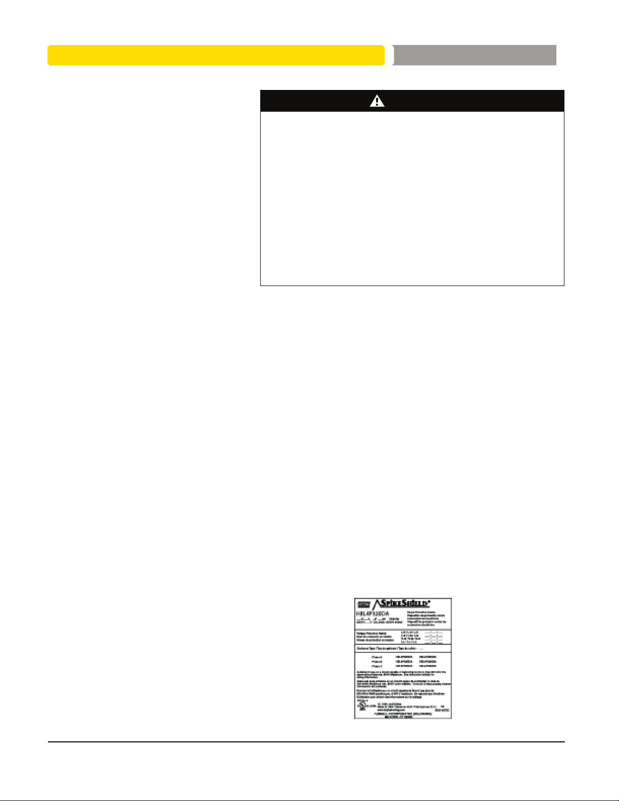
Identification Nameplate............................................................................5
Surge Protective Device (SPD) Location Considerations .....................5
Environment ................................................................................................5
Audible Noise ..............................................................................................5
Mounting ......................................................................................................5
Service Clearance .......................................................................................5
Equipment Performance ..............................................................................5
Electrical ....................................................................................................5
Voltage Rating .............................................................................................5
Terminals, Wire Size, and Installation Torque .............................................7
Branch Circuit Overcurrent Protection .........................................................7
Location of Surge Protective Device (SPD) ................................................7
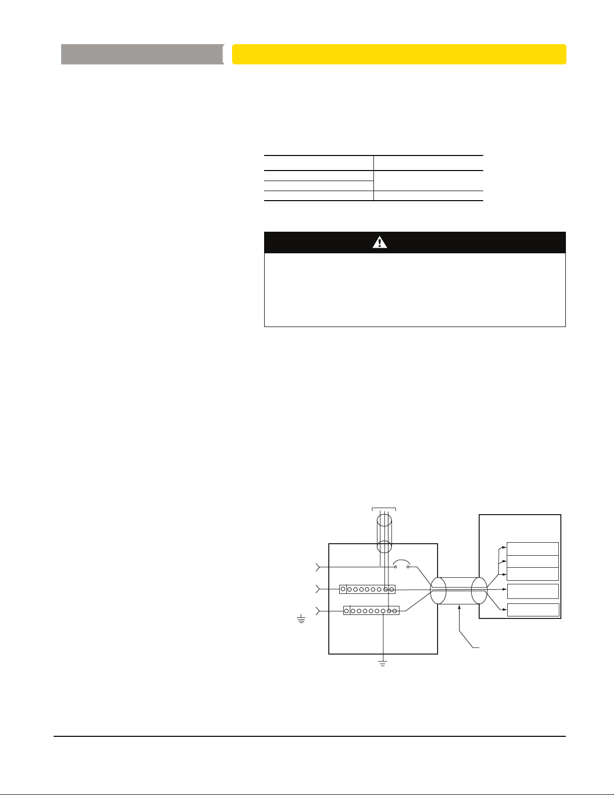
Grounding ..................................................................................................8
General ........................................................................................................8
Power System Grounding ...........................................................................8
Solidly-Grounded Power Systems ...............................................................9
Resistance-Grounded Power Systems .......................................................9
Installation ...............................................................................................10
Conduit Location and Recommendations .................................................10
Special Enclosure Considerations .............................................................10
Removing and Reconnecting the RJ45 Diagnostic Cables .................10
Optional Flush Mounting ......................................................................10
Wiring .......................................................................................................10
Dimension and Weights EMA Series .........................................................12
Wiring Diagrams Without Integral Switch ..................................................13
Wiring Diagrams With Integral Switch .......................................................16
Operation .................................................................................................21
LED Status Indicators ................................................................................21
Replacement Modules ...............................................................................23
Audible Alarm ............................................................................................22
Surge Counter ...........................................................................................22
Dry Contacts ..............................................................................................22
Maintenance and Troubleshooting ........................................................24
Preventative Maintenance .........................................................................24
Troubleshooting .........................................................................................25
Replacement Parts ....................................................................................25
Electrical equipment should only be installed, operated, serviced and maintained by qualified personnel. ______________________________Hubbell Wiring Devices
No responsibility is assumed by Hubbell for any consequences arising out of the use of this material. _________________1-800-729-3406 | www.Hubbell-Wiring.com
#SpikeShield® Modular Panel Surge Protective Device (SPD)
CONTENTS

Electrical equipment should only be installed, operated, serviced and maintained by qualified personnel. ______________Hubbell Wiring Devices
No responsibility is assumed by Hubbell for any consequences arising out of the use of this material. __1-800-729-3406 | www.Hubbell-Wiring.com
3
Precautions
HAZARD OF ELECTRIC SHOCK, EXPLOSION, OR ARC FLASH
• Apply appropriate personal protective equipment (PPE) and follow safe
electrical work practices. See NFPA 70E.
• This equipment must only be installed and serviced by qualified electrical
personnel.
• Turn off all power supplying this equipment before working on or inside
equipment.
• Always use a properly rated voltage sensing device to confirm power is off.
• Replace all devices, doors and covers before turning on power to this
equipment.
• This equipment must be effectively grounded per all applicable codes. Use
an equipment-grounding conductor to connect this equipment to the power
system ground.
Failure to follow these instructions will result in death or serious injury.
LOSS OF BRANCH CIRCUIT POWER/LOSS OF SURGE SUPPRESSION
• Perform periodic inspection of the SPD status indicator lights as part of the
preventative maintenance schedule.
• Promptly service the SPD when an alarm state exists.
• Use dry contacts to signal an alarm state to the central supervisory system
for unmanned, inaccessible, or critical installations.
• Use multiple SPDs to achieve redundancy for critical applications.
Failure to follow these instructions can result in injury or equipment
damage.
At end-of-life conditions, Surge Protective Devices (SPDs) can lose their ability
to block power system voltage and attempt to draw excessive current from the
line. This SPD is equipped with overcurrent and overtemperature components
that will automatically disconnect the surge suppression elements from the
mains should the surge suppression elements reach end of life. Tripping of the
branch circuit breaker or fuse feeding the SPD can occur when the surge
suppression elements reach end of life.
LOSS OF SURGE SUPPRESSION
• Do not energize the Surge Protective Device until the electrical system is
completely installed, inspected, tested, and all conductors have been
connected and functional, including the neutral.
• Verify the voltage rating of the device and system before energizing the
Surge Protective Device.
• Perform high-potential insulation testing, or any other tests where SPD
components will be subjected to voltages higher than their rated turn-on
voltage, with the neutral and SPD disconnected from the power source.
Failure to follow these instructions can result in injury or equipment
damage.
DANGER
CAUTION
CAUTION
PRECAUTIONS SpikeShield® Modular Panel Surge Protective Device (SPD)

8232-0081 _______________________________________________________________________________________Hubbell Wiring Devices
Rev. 02, 06/2017___________________________________________________________________1-800-729-3406 | www.Hubbell-Wiring.com
4
Introduction
HAZARD OF ELECTRIC SHOCK, EXPLOSION, OR ARC FLASH
• Apply appropriate personal protective equipment (PPE) and follow safe
electrical work practices. See NFPA 70E.
• This equipment must only be installed and serviced by qualified electrical
personnel.
• Turn off all power supplying this equipment before working on or inside
equipment.
• Always use a properly rated voltage sensing device to confirm power is off.
• Replace all devices, doors and covers before turning on power to this
equipment.
• This equipment must be effectively grounded per all applicable codes. Use
an equipment-grounding conductor to connect this equipment to the power
system ground.
Failure to follow these instructions will result in death or serious injury.
Note: For assistance, call a Hubbell representative
at 1-800-729-3406.
Proper installation is imperative to maximize the SPD’s surge protective device’s
effectiveness and performance. Read the entire instruction bulletin before
beginning the installation. These instructions are not intended to replace
national or local electrical codes. Check all applicable electrical codes to verify
compliance. Installation of modular surge suppressors should only be
performed by qualified electrical personnel.
Unpacking and Preliminary
Inspection
Inspect the entire shipping container for damage or signs of mishandling before
unpacking the device. Remove the packing material and further inspect the
device for any obvious shipping damage. If any damage is found and is a result
of shipping or handling, immediately file a claim with the shipping company.
Storage The device should be stored in a clean, dry environment. Storage temperature is
-40 °F to +149 °F (-40 °C to +65 °C). All of the packaging materials should be left
intact until the device is ready for installation.
Safety Labels English versions of all safety labels (Danger, Warning, and Caution) are
provided.
Identification Nameplate The identification nameplate is located on the inside of the door/cover.
Figure 1: Surge Protective Device Nameplate Example
DANGER
SpikeShield® Modular Panel Surge Protective Device (SPD) INTRODUCTION

Electrical equipment should only be installed, operated, serviced and maintained by qualified personnel. ______________Hubbell Wiring Devices
No responsibility is assumed by Hubbell for any consequences arising out of the use of this material. __1-800-729-3406 | www.Hubbell-Wiring.com
5
Surge Protective Device
(SPD) Location
Considerations
Environment The device is designed to operate in an ambient temperature range of
-4 °F to +149 °F (-20 °C to +65 °C) with a relative humidity of 0 to 95% non-
condensing. The operating temperature of the LCD on the diagnostic display
panel is +14 °F to +140 °F (-10 °C to +60 °C). Refer to the product catalog for
further details on enclosures. All SpikeShield®devices operate normally without
reduction in performance when subjected to shock and vibrations described in
IEC 60721-3-3, Class 3M4.
Audible Noise The background noise is negligible and does not restrict the location of the
installation.
Mounting The device is designed to be surface or flush mounted. Refer to the device
submittal drawings or the product catalog for typical mounting dimensions and
weight.
Service Clearance The service clearance should meet all applicable code requirements.
Equipment Performance To obtain the maximum system performance, locate the device as close to the
circuit being addressed as possible to minimize the interconnecting wiring
length. For every foot of wire length, approximately 160 Volts (6 kV / 3 kA, 8/20
microsecond) is added to the suppressed voltage. The Voltage Protection
Rating (VPR) is located on the device nameplate and is measured six inches
from the enclosure sidewall, according to UL 1449 test standards.
Electrical
Voltage Rating
HAZARD OF ELECTRIC SHOCK, EXPLOSION, OR ARC FLASH
Confirm the SPD voltage rating on the module or nameplate label is the
same as the operating voltage.
Failure to follow these instructions will result in death or serious injury.
Prior to mounting the SPD, verify that the device has the same voltage rating as
the power distribution system in which it is installed. Compare the nameplate
voltage or model number on the SPD with the nameplate of the electrical
distribution equipment.
The specifier or user of the device must be familiar with the configuration and
arrangement of the power distribution system in which any SPD is to be
installed. The system configuration of any power distribution system is based
strictly on how the secondary windings of the transformer supplying the service
entrance main or load are configured. This includes whether or not the
transformer windings are referenced to earth via a grounding conductor. The
system configuration is not based on how any specific load or equipment is
connected to a particular power distribution system. See Table 1 for the service
voltage of each SPD.
DANGER
SpikeShield® Modular Panel Surge Protective Device (SPD)
INTRODUCTION

Table 1: Voltage Ratings
Service Voltage Peak Surge Current
Rating Per Phase
120 kA HBL3P120C
160 kA HBL3P160B
160 kA HBL3P160DB
320 kA HBL3P320B
320 kA HBL3P320DB
208/120 V2
2208Y/120 series also applies to the following voltage: 220Y/127.
, 3-phase,
4-wire + ground Wye
120 kA HBL4P120C
160 kA HBL4P160B
160 kA HBL4P160DB
320kA HBL4P320B
320 kA HBL4P320DB
240/120 V, 3-phase,
4-wire + ground
High-leg Delta
120 kA HBL6P120C
160 kA HBL6P160B
160 kA HBL6P160DB
320kA HBL6P320B
320 kA HBL6P320DB
240 V, 3-phase,
3-wire + ground
Delta
160 kA HBL5P160B
160 kA HBL5P160DB
320 kA HBL5P320B
320 kA HBL5P320DB
480Y/277 V, 3-phase,
4-wire + ground
Wye 3
3480Y/277 series also applies to the following voltages: 380Y/220, 400Y/230 and 415Y/240.
120 kA HBL8P120C
160 kA HBL8P160B
160 kA HBL8P160DB
320 kA HBL8P320B
320 kA HBL8P320DB
480 V, 3-phase,
3-wire + ground
Delta 4
4480 V Delta series also applies to the following voltages: 480Y/277V HRG.
120 kA HBL9P120C
160 kA HBL9P160B
160 kA HBL9P160DB
320 kA HBL9P320B
320 kA HBL9P320DB
600Y/347 V, 3-phase,
4-wire + ground Wye
120 kA HBL10P120C
160 kA HBL10P160B
160 kA HBL10P160DB
320kA HBL10P320B
320 kA HBL10P320DB
600 V, 3-phase,
3-wire + ground
Delta 5
5600 V Delta series also applies to the following voltages: 600Y/347V HRG.
120 kA HBL11P120C
160 kA HBL11P160B
160 kA HBL11P160DB
320 kA HBL11P320B
320 kA HBL11P320DB
8232-0081 _______________________________________________________________________________________Hubbell Wiring Devices
Rev. 02, 06/2017___________________________________________________________________1-800-729-3406 | www.Hubbell-Wiring.com
6
Catalog Numbers 1
1Enclosure option or another other option.
120/240 V, 1-phase,
3-wire + ground
SpikeShield® Modular Panel Surge Protective Device (SPD) ELECTRICAL

Electrical equipment should only be installed, operated, serviced and maintained by qualified personnel. ______________Hubbell Wiring Devices
No responsibility is assumed by Hubbell for any consequences arising out of the use of this material. __1-800-729-3406 | www.Hubbell-Wiring.com
7
Terminals, Wire Size, and
Installation Torque
Terminals are provided for phase (line), neutral, and equipment ground
connections. The terminals accept a range of 10 AWG to 2 AWG copper wire for
the offer without internal switch for phase, neutral and ground connectors and
10 AWG to 3/0 AWG copper wire for the switch offer for phase connectors.
Torque connections to the following values:
Table 2: Terminal Torque
Power Connection Torque
AØ, BØ, CØ and N 40 lb-in. (4 N•m)
Ground
Switch 50 lb-in. (5 N•m)
Branch Circuit Overcurrent
Protection
HAZARD OF ELECTRIC SHOCK, EXPLOSION, OR ARC FLASH
• Use conductors rated for the Overcurrent Protection Device (OCPD) per
applicable codes.
• Use conductors rated for the application per applicable codes.
Failure to follow these instructions will result in death or serious injury.
UL 1449 Type 1 SPDs have been designed and approved for line side
applications prior to the main service disconnect without supplemental
overcurrent protection. Type 1 SPDs may also be installed on the load side of
the main Overcurrent Protection Device (OCPD).
Location of Surge Protective
Device (SPD)
Locate the SPD as close as possible to the circuit being addressed to minimize
the wire length and optimize SPD performance. Avoid long wire runs so that the
device will perform as intended. To reduce wire impedance from surge currents,
the phase, neutral, and ground conductors must be routed within the same
conduit and tightly bundled or twisted together to optimize device performance.
Avoid sharp bends in the conductors. See Figure 2.
Figure 2: Surge Protective Device Wiring Practice
To load(s)
Phases
Neutral
(if applicable)
Ground
Ground bus
Neutral bus
SPD
Phase A
Phase B
Phase C
Neutral
(if applicable)
Ground
Interconnect wiring
– Minimize length
– Avoid sharp bends
Panel
DANGER
SpikeShield® Modular Panel Surge Protective Device (SPD)
ELECTRICAL

8232-0081 _______________________________________________________________________________________Hubbell Wiring Devices
Rev. 02, 06/2017___________________________________________________________________1-800-729-3406 | www.Hubbell-Wiring.com
8
Grounding
HAZARDOUS TOUCH VOLTAGE
• Connect the Surge Protective Device ground terminal to the building
grounding grid structure.
• Use an appropriately sized equipment grounding conductor.
• When using metallic raceway or conduit:
— Do not use isolated bushings to interrupt the metallic raceway or conduit.
— Maintain electrical continuity at all raceway and conduit connections using
appropriate bonding devices.
• Do not use a separate isolated ground for the Surge Protective Device.
• Verify proper equipment connection to the grounding system.
• Verify ground grid continuity by performing regularly scheduled inspections
and testing as part of a comprehensive electrical maintenance program.
Failure to follow these instructions can result in death or serious injury.
General The device has SPD elements connected from phase to ground. It is critical that
there be a robust and effective connection to the building grounding structure.
The grounding connection must utilize an equipment grounding conductor run
with the phase and neutral (if present) connection of the power system.
For best over-voltage suppression by the SPD, use a single-point ground
system where the service entrance grounding electrode system is connected to,
and bonded to, all other available electrodes, building steel, metal water pipes,
driven rods, etc. (for reference, see IEEE 142-2007). The ground impedance
measurement of the electrical system should be as low as possible, and in
compliance with all applicable codes.
Power System Grounding In addition to the power system configuration and voltage, the power system
grounding method must be considered when selecting the appropriate SPD.
Refer to the following chart for information concerning the suitability of the
SpikeShield SPDs to specific power system grounding method.
Table 3: Grounding Methods
WARNING
SpikeShield® Modular Panel Surge Protective Device (SPD) GROUNDING
Catalog Number Power System Grounding Method
HBL3P_
Solidly-Grounded
HBL4P_
HBL6P_
HBL8P_
HBL10P_
HBL9P_
Ungrounded / HRGHBL5P_
HBL11P_

Electrical equipment should only be installed, operated, serviced and maintained by qualified personnel. ______________Hubbell Wiring Devices
No responsibility is assumed by Hubbell for any consequences arising out of the use of this material. __1-800-729-3406 | www.Hubbell-Wiring.com
9
Solidly-Grounded Power Systems
SPD DAMAGE AND POWER SYSTEM OVERVOLTAGE
• Do not connect devices rated for use on solidly-grounded power systems to
resistance-grounded (for example, High Resistance Ground) or ungrounded
power systems.
• Verify that the service entrance equipment is bonded to ground in
accordance with all applicable codes.
• Verify that the neutral terminal of the power system transformer feeding the
device is bonded to system ground in accordance with all applicable codes.
Failure to follow these instructions can result in injury or equipment.
damage
SPDs rated for use on solidly-grounded power systems must not be connected to
resistance-grounded or ungrounded power systems. Such a connection can result
in damage to the SPD.
Always verify the power system grounding configuration prior to application of
power to the device. Confirm that all ground bonds are installed at both the
service entrance equipment and power system transformer prior to application of
power.
Delta and Resistance-Grounded
Power Systems
SPD DAMAGE AND POWER SYSTEM OVERVOLTAGE
• Ungrounded power systems are inherently unstable and can produce
excessively high line-to-ground voltages during certain fault conditions.
During these fault conditions any electrical equipment, including an SPD,
may be subjected to voltages which exceed their designed ratings. This
information is being provided to the user so that an informed decision can
be made before installing any electrical equipment on an ungrounded power
system.
• Resistance-grounded power systems must be maintained in an over-
damped state to limit voltage overshoot and duration during operation.
• Verification and adjustment of correct power system damping should be
done:
— Periodically as part of normal system maintenance.
— Following power system modifications.
Failure to follow these instructions can result in injury or equipment
damage.
The SPD product is intended for use on resistance-grounded power systems
where the power system has been set for, and is maintained in, an over-damped
state. For the power system to be over-damped, the current through the
grounding resistor during a bolted phase-to-ground fault must be significantly
greater than the total charging current of the system.
Periodic engineering evaluation of the power system is required to determine the
worst-case charging current of the system and to adjust the grounding
resistance accordingly. As the power system is modified, the value of the
grounding resistor must be evaluated and adjusted to maintain the system in the
over-damped state.
CAUTION
CAUTION
SpikeShield® Modular Panel Surge Protective Device (SPD)
GROUNDING

8232-0081 _______________________________________________________________________________________Hubbell Wiring Devices
Rev. 02, 06/2017___________________________________________________________________1-800-729-3406 | www.Hubbell-Wiring.com
10
Installation
HAZARD OF ELECTRIC SHOCK, EXPLOSION, OR ARC FLASH
• Apply appropriate personal protective equipment (PPE) and follow safe
electrical work practices. See NFPA 70E.
• This equipment must only be installed and serviced by qualified electrical
personnel.
• Turn off all power supplying this equipment before working on or inside
equipment.
• Always use a properly rated voltage sensing device to confirm power is off.
• Replace all devices, doors and covers before turning on power to this
equipment.
• This equipment must be effectively grounded per all applicable codes. Use
an equipment-grounding conductor to connect this equipment to the power
system ground.
Failure to follow these instructions will result in death or serious injury.
Conduit Location and
Recommendations
The recommended conduit entry is at the bottom or either side of the device
enclosure. Use a conduit seal that is appropriate for the enclosure rating.
Special Enclosure Considerations
Removing and Reconnecting the RJ45
Diagnostic Cables
The diagnostic cables are marked with matching phase connections. If any of
the cables are removed, reconnect the cables as marked.
Optional Flush Mounting The flush mount collar option provides a mechanical means to install the surge
suppressor flus to the surface of sheetrock or firewall construction.
Wiring
HAZARD OF ELECTRIC SHOCK, EXPLOSION, OR ARC FLASH
• Apply appropriate personal protective equipment (PPE) and follow safe
electrical work practices. See NFPA 70E.
• This equipment must only be installed and serviced by qualified electrical
personnel.
• Turn off all power supplying this equipment before working on or inside
equipment.
• Always use a properly rated voltage sensing device to confirm power is off.
• Replace all devices, doors and covers before turning on power to this
equipment.
• This equipment must be effectively grounded per all applicable codes. Use
an equipment-grounding conductor to connect this equipment to the power
system ground.
• Confirm the SPD voltage rating on the module or nameplate label is the
same as the operating voltage.
• Do not touch the bottom located terminals which are energized with the
switch in either the ON or OFF positions.
Failure to follow these instructions will result in death or serious injury.
DANGER
DANGER
SpikeShield® Modular Panel Surge Protective Device (SPD) INSTALLATION

Electrical equipment should only be installed, operated, serviced and maintained by qualified personnel. ______________Hubbell Wiring Devices
No responsibility is assumed by Hubbell for any consequences arising out of the use of this material. __1-800-729-3406 | www.Hubbell-Wiring.com
11
Follow the steps listed below when making wiring connections:
1. Turn off all power supplying this equipment before working on or inside any
enclosure containing this equipment.
2. Confirm the SPD voltage rating and configuration is the same as the system
voltage and power system configuration to which it will be connected.
3. Identify proper location for surge protective device. Locate as close as
possible to the panel being addressed so the wires are as short as possible.
Mount unit securely.
Note: The surge protective device must be installed in an accessible
location as described in the NEC.
4. Install in accordance with national and local electrical codes for overcurrent
protection recommendations and wire ampacity considerations.
Note: The neutral connection is not present on three-phase, three-wire WYE
solidly ground or two-wire single-phase mid-point ground power systems.
For these systems, bond the neutral and ground lugs together in the SPD.
For a High Resistance Ground (HRG) or Delta SPD, no neutral connection
exists. For installation wiring see Figures 7 through 14.
Note: See “Terminals, Wire Size, and Installation Torque” and Table 2 on
page 7 for acceptable wire size and installation torque.
5. Twist conductors 1/2 turn or more for every twelve inches of length. Do not
loop or coil wires. Be sure to maintain adequate wire bending space per
NEC.
6. If the remote signaling contacts of the diagnostic display panel are to be
used, refer to the section, “Dry Contact”, on page 25 for wiring instructions.
7. On a high-leg delta installation, note the high leg connection per wiring
diagram. See Figure 11.
8. Replace all devices, doors, and covers before turning on power to the
equipment. If the SPD is properly installed and functioning, the green LED
indicators on the display will be lit.
If you have any questions pertaining to the installation of this device, contact
Hubbell at 1-800-729-3406.
SpikeShield® Modular Panel Surge Protective Device (SPD)
WIRING

8232-0081 _______________________________________________________________________________________Hubbell Wiring Devices
Rev. 02, 06/2017___________________________________________________________________1-800-729-3406 | www.Hubbell-Wiring.com
12
Dimension and Weights Series Figure 3: 11 x 12 in. NEMA 1 Enclosures
Approximate Weight 23 lbs (10.4 kg)
Figure 4: 11 x 20 in. NEMA 1 Enclosures with Integral Switch
Approximate Weight 27 lbs (12.2 kg)
Figure 5: 11 x 22 in. NEMA 1 Enclosures for 320 kA and 480 kA units
with or without Integral Switch
Approximate Weight 37 lbs (16.8 kg)
11.04
11.44
5.32
8.86
9.60
R.24
R.12
.38
(208)
(290)
(135) (243)
(225)
(9.6)
(3.0)
(6.0)
in.
(mm)
Dimensions:
R. 12
(3.0)
R. 24
(6.0)
Dimensions: in.
(mm)
.38
(9.6)
9.84
(250)
11.04
(280.0)
5.32
(135)
20.32
(516)
17.38
(441)
R. 12
(3.0)
R. 24
(6.0)
Dimensions: in.
(mm)
.38
(9.6)
11.04
(280.0)
7.87
(200.0)
9.64
(245.0)
22.44
(570.0)
20.00
(508.0)
SpikeShield® Modular Panel Surge Protective Device (SPD) WIRING

Electrical equipment should only be installed, operated, serviced and maintained by qualified personnel. ______________Hubbell Wiring Devices
No responsibility is assumed by Hubbell for any consequences arising out of the use of this material. __1-800-729-3406 | www.Hubbell-Wiring.com
13
Wiring Diagrams Without Integral Switch
Figure 6: Single-Phase, Three-Wire Grounded Installation
Note: The neutral conductor is not present on two-wire grounded
power systems. For these systems, bond the neutral and ground lugs
together inside the SPD using 10 AWG wire.
NEUTRAL
GROUND
PHASE C
N
A
C
See Note
PHASE A
Ground
Phase
A
Neutral
Phase C
Ground
Phase
A
Phase C
Neutral
Customer Connections 120-240 kA Customer Connections 320-480 kA
SURGE PROTECTIVE DEVICE
Push-to-Test: =OK =Replace Module
Surge
Counter
Audible
Alarm
AØ CØ
8232-0031REV 01
SURGE PROTECTIVE DEVICE
Push-to-Test: =OK =Replace Module
Surge
Counter
Audible
Alarm
AØ CØ
8232-0031REV 01
SpikeShield® Modular Panel Surge Protective Device (SPD)
WIRING

8232-0081 _______________________________________________________________________________________Hubbell Wiring Devices
Rev. 02, 06/2017___________________________________________________________________1-800-729-3406 | www.Hubbell-Wiring.com
14
Figure 7: Three-Phase, Three- or Four-Wire, Grounded Wye Installation
SPD
Note: The neutral conductor is not present on three-wire grounded
power systems. For these systems, bond the neutral and ground
lugs together inside the SPD using 10 AWG wire. PHASE A
PHASE B
NEUTRAL
GROUND
PHASE C
A
B
N
C
See Note
Customer Connections 120-240 kA Customer Connections 320-480 kA
Ground
Phase A
Neutral
Phase C
Phase B Phase A
Phase B
Phase C
Neutral
Ground
SURGE PROTECTIVE DEVICE
Push-to-Test: =OK =Replace Module
Surge
Counter
Audible
Alarm
AØ BØ CØ
8232-0031REV 01
SURGE PROTECTIVE DEVICE
Push-to-Test: =OK =Replace Module
Surge
Counter
Audible
Alarm
AØ BØ CØ
8232-0031REV 01
SpikeShield® Modular Panel Surge Protective Device (SPD) WIRING

Electrical equipment should only be installed, operated, serviced and maintained by qualified personnel. ______________Hubbell Wiring Devices
No responsibility is assumed by Hubbell for any consequences arising out of the use of this material. __1-800-729-3406 | www.Hubbell-Wiring.com
15
Figure 8: Three-Phase, Three- or Four-Wire, High-Leg Delta Installation
SPD
Note: The high-leg of the power system must connect to phase B of
the SPD. The neutral conductor is not present on three-wire grounded
power systems. For these systems, bond the neutral and ground lugs
together inside the SPD using 10 AWG wire.
PHASE C
PHASE A
PHASE B
See Note
NEUTRAL
GROUND
N
B
C
A
Customer Connections 120-240 kA Customer Connections 320-480 kA
Ground
Phase A
Neutral
Phase C
Phase B Phase A
Phase B
Phase C
Neutral
Ground
SURGE PROTECTIVE DEVICE
Push-to-Test: = OK = Replace Module
Surge
Counter
Audible
Alarm
AØ BØ CØ
8232-0031REV 01
SURGE PROTECTIVE DEVICE
Push-to-Test: = OK = Replace Module
Surge
Counter
Audible
Alarm
AØ BØ CØ
8232-0031REV 01
SpikeShield® Modular Panel Surge Protective Device (SPD)
WIRING

8232-0081 _______________________________________________________________________________________Hubbell Wiring Devices
Rev. 02, 06/2017___________________________________________________________________1-800-729-3406 | www.Hubbell-Wiring.com
16
Wiring Diagrams With Integral
Switch
Figure 9: Single-Phase, Three-Wire, Grounded Installation Integral Switch
Note: The neutral conductor is not present on two-wire grounded
power systems. For these systems, bond the neutral and ground lugs
together inside the SPD using 10 AWG wire.
SPD
NEUTRAL
GROUND
PHASE C
N
A
C
See Note
PHASE A
Customer Connections 320-480 kACustomer Connections 120-240 kA
Ground
Phase A
Neutral
Phase C
Phase A
Phase C
Ground
Neutral
SURGE PROTECTIVE DEVICE
Push-to-Test: = OK = Replace Module
Surge
Counter
Audible
Alarm
AØ CØ
8232-0031REV 01
SURGE PROTECTIVE DEVICE
Push-to-Test: = OK = Replace Module
Surge
Counter
Audible
Alarm
AØ CØ
8232-0031REV 01
SpikeShield® Modular Panel Surge Protective Device (SPD) WIRING

Electrical equipment should only be installed, operated, serviced and maintained by qualified personnel. ______________Hubbell Wiring Devices
No responsibility is assumed by Hubbell for any consequences arising out of the use of this material. __1-800-729-3406 | www.Hubbell-Wiring.com
17
Figure 10: Three-Phase, Three- or Four-Wire, Grounded Wye Installation with Integral Switch
SPD
Note: The neutral conductor is not present on three-wire grounded
power systems. For these systems, bond the neutral and ground
lugs together inside the SPD using 10 AWG wire.
PHASE C
PHASE A
PHASE B
NEUTRAL
GROUND
N
See Note
A
B
C
Customer Connections 320-480 kACustomer Connections 120-240 kA
Ground
Phase A
Neutral
Phase C
Phase B
Phase A
Phase C
Phase B
Ground
Neutral
SURGE PROTECTIVE DEVICE
Push-to-Test: = OK = Replace Module
Surge
Counter
Audible
Alarm
AØ BØ CØ
8232-0031REV 01
SURGE PROTECTIVE DEVICE
Push-to-Test: = OK = Replace Module
Surge
Counter
Audible
Alarm
AØ BØ CØ
8232-0031REV 01
SpikeShield® Modular Panel Surge Protective Device (SPD)
WIRING

Figure 11: Three-Phase, Three- or Four-Wire, High-Leg Delta Installation with Integral Switch
SPD
Note: The high-leg of the power system must connect to phase B of the
SPD. The neutral conductor is not present on three-wire grounded
power systems. For these systems, bond the neutral and ground lugs
together inside the SPD using #10 AWG wire.
PHASE C
PHASE B
PHASE A
NEUTRAL
GROUND
See Note
N
A
C
B
Customer Connections 320-480 kACustomer Connections 120-240 kA
Ground
Phase A
Neutral
Phase C
Phase B
Phase A
Phase C
Phase B
Ground
Neutral
SURGE PROTECTIVE DEVICE
Push-to-Test: = OK = Replace Module
Surge
Counter
Audible
Alarm
AØ BØ CØ
8232-0031REV 01
SURGE PROTECTIVE DEVICE
Push-to-Test: = OK = Replace Module
Surge
Counter
Audible
Alarm
AØ BØ CØ
8232-0031REV 01
8232-0081 _______________________________________________________________________________________Hubbell Wiring Devices
Rev. 02, 06/2017___________________________________________________________________1-800-729-3406 | www.Hubbell-Wiring.com
18
SpikeShield® Modular Panel Surge Protective Device (SPD) WIRING

Electrical equipment should only be installed, operated, serviced and maintained by qualified personnel. ______________Hubbell Wiring Devices
No responsibility is assumed by Hubbell for any consequences arising out of the use of this material. __1-800-729-3406 | www.Hubbell-Wiring.com
19
SPD
See Note
(below)
Ground
Phase B
Phase C
Phase A
B
A
C
SPD
See Note
(above)
Ground
Phase B
Phase C
Phase A
B
A
C
Corner Grounded Delta Ungrounded Delta
Note: The ground connection of the Delta SPD shall be connected to the system
ground conductor. The neutral conductor is not present on Delta systems.
Note: Phase B of the electrical system is typically the grounded phase
Customer Connections 320-480 kACustomer Connections 100-240 kA
Ground
Phases (A, B, C) Phase A
Phase B
Phase C
Ground
Customer Connections 320-480 kA with Integral Switch
Customer Connections 100-240 kA with Integral Switch
Ground
Phase A
Phase C
Phase B
Phase A
Phase C
Phase B
Ground
SURGE PROTECTIVE DEVICE
Push-to-Test: = OK = Replace Module
Surge
Counter
Audible
Alarm
AØ BØ CØ
8232-0031REV 01
SURGE PROTECTIVE DEVICE
Push-to-Test: = OK = Replace Module
Surge
Counter
Audible
Alarm
AØ BØ CØ
8232-0031REV 01
SURGE PROTECTIVE DEVICE
Push-to-Test: = OK = Replace Module
Surge
Counter
Audible
Alarm
AØ BØ CØ
8232-0031REV 01
SURGE PROTECTIVE DEVICE
Push-to-Test: = OK = Replace Module
Surge
Counter
Audible
Alarm
AØ BØ CØ
8232-0031REV 01
Figure 12: Three-Phase, Three-Wire + Ground, Delta Installation
SpikeShield® Modular Panel Surge Protective Device (SPD)
WIRING

8232-0081 _______________________________________________________________________________________Hubbell Wiring Devices
Rev. 02, 06/2017___________________________________________________________________1-800-729-3406 | www.Hubbell-Wiring.com
20
Figure 13: High Resistance Ground HRG Wye Installation
Note: The neutral conductor is not present on HRG WYE
grounded power systems.
Customer Connections 320-480 kACustomer Connections 100-240 kA
Ground
Phases (A, B, C) Phase A
Phase B
Phase C
Ground
Customer Connections 320-480 kA with Integral SwitchCustomer Connections 100-240 kA with Integral Switch
Ground
Phase A
Phase C
Phase B
Phase A
Phase C
Phase B
Ground
SURGE PROTECTIVE DEVICE
Push-to-Test: = OK = Replace Module
Surge
Counter
Audible
Alarm
AØ BØ CØ
8232-0031REV 01
SURGE PROTECTIVE DEVICE
Push-to-Test: = OK = Replace Module
Surge
Counter
Audible
Alarm
AØ BØ CØ
8232-0031REV 01
SURGE PROTECTIVE DEVICE
Push-to-Test: = OK = Replace Module
Surge
Counter
Audible
Alarm
AØ BØ CØ
8232-0031REV 01
SURGE PROTECTIVE DEVICE
Push-to-Test: = OK = Replace Module
Surge
Counter
Audible
Alarm
AØ BØ CØ
8232-0031REV 01
PHASE A
PHASE B
GROUND
PHASE C
See Note
A
B
C
SpikeShield® Modular Panel Surge Protective Device (SPD) WIRING
This manual suits for next models
37
Table of contents
Other Hubbell Protection Device manuals