Press and hold the Power button for more than 2s, the battery light
will flash once, then the LED will light up in turn, and when the top most
running light flashes fast for about 10 times, it means that the system
parallel programming is successful and the battery is running normally.
6. System Start Up
STEP-1:
After installing the fixed battery, measure the voltage of the
STEP-2:
To connect the parallel communication cable between the
batteries, the link-in of the Master battery, i.e. the first machine,
needs to be plugged in with a plug (to short pin1 and pin6),
the link-out interface uses a parallel communication cable
V1.0.2
10-203-00311-01
replace the battery.
to determine whether there is a voltage output, and if so,
positive and negative terminals of the battery with a multimeter
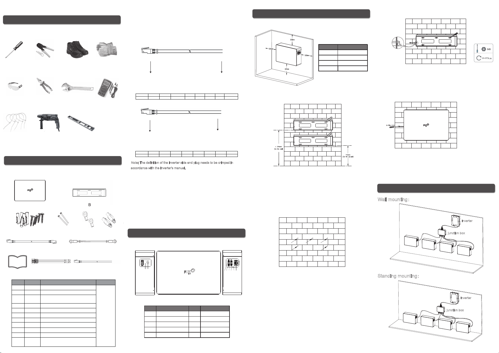
STEP-3:
Connect the BAT+ and BAT- of the battery to the input of the
junction box (not included in the package), and then connect the
output of the junction box to the inverter; connect one of the
Note: the length of the power line needs to be the same when
(pin to pin network cable) to the link-in interface of the next battery,
and so on, and the last link-out interface is plugged in with a plug
(to short pin1 and pin6).
in parallel mode.
Stand-alone mode:
STEP-1:
After installing the fixed battery,
measure the voltage of the positive and negative terminals of
the battery with a multimeter to
determine whether there is a
voltage output, and if so,
STEP-2:
Plug the 2 plugs (to short pin1
and pin6) into the parallel
communication interface LINK-IN and LINK-OUT of the battery
respectively.
STEP-3:
Connect the BAT+ and BAT- of the battery to the corresponding
positive and negative terminals of the inverter; connect one of the
communication interface PCS of the battery to the interface of the
communication between the inverter and the battery; connect the
ground wire.
replace the battery.
Parallel mode:
Note: Different model of batteries cannot be mixed in one system,
any further questions related to the battery versions please
Connect the ground wire of each battery.
Lead-acid function:
Battery capacity: 104Ah
In the above two modes, when operating according to the
corresponding steps, the communication harness between the
battery and the inverter is not connected, and the battery enters
the lead-acid function by default; Both stand-alone mode and
parallel mode have lead-acid function.
When the battery uses the lead-acid function, the matching
inverter needs to be set to lead-acid mode as well, and the
following parameters need to be set on the inverter:
Charging voltage: 57.0V
Charging protection voltage: 57.6V
Float voltage: 53.0V
Maximum charging current: 50A
Discharge cut-off voltage: 48.0V
Maximum discharge current: 100A
Forced charging voltage: 48.0V
Battery internal resistance: 15mΩ
Note: Under the lead-acid function, the battery does not
communicate with the inverter, and the inverter will not display the
SOC information of the battery.
Note: Parallel mode supports up to 4 batteries in parallel.
Master battery Last battery
communication interface PCS of the Master battery to the interface
of the communication between the inverter and the battery;