Hugo Lahme FitStar Cyclon User manual

1
a brand of Hugo Lahme GmbH
FITSTAR - Gegenschwimmanlagen
Cyclon und Cyclon Duo
FITSTAR - counter-current-systems
Cyclon and Cyclon Duo
FITSTAR - nages à contre-courant
Cyclon et Cyclon Duo
Stand 08/2010
Art. Nr.: 577701
a brand of Hugo Lahme GmbH

2
a brand of Hugo Lahme GmbH
Stand 08/2010 Art. Nr.: 577701
Anschlusssatz Cyclon und Cyclon Duo
Fittings Cyclon and Cyclon Duo
Ensemble de raccordement Cyclon et Cyclon Duo
ACHTUNG:
Bei Wasserattraktionen kann während längerer Stillstandzeiten das stagnierende Wasser im Rohrsystem
verkeimen und dadurch das Beckenwasser hygienisch belasten. Um dieser Verkeimungsgefahr
entgegenzuwirken und die hygienische Anforderung der DIN zu erfüllen, wird empfohlen, einen
Teilstrom des Reinwassers über einen geregelten Bypass zur Zwangsdurchströmung in das Rohrsystem
der Wasserattraktionen zu führen.
Eine weitere Möglichkeit zur Erhaltung der erforderlichen Grenzwerte ist ebenfalls über eine Zwangslauf-
schaltung gegeben.
ATTENTION:
Regarding water attractions the stagnation water in the tubing system may germinate and load the basin
water in an insanitary way during longer downtimes. For avoiding any germination risc and for
fulfilling the sanitary demand of the DIN standard, it is recommended to lead a part of the pure water
flow through a regulated bypass. The purpose of this measure consists of creating a forced current into
the tubing system of the water attraction.
Another possibility for maintaining the necessary limit values is a controlled movement circuit.
ATTENTION:
Les attractions aquatiques peuvent, lors d`un arrêt prolongé, avoir une contamination d`eau stagnante
dans les tuyauteries. Cette possibilité peut provoquer une contamination bactérielle résiduelle dans le
volume du bassin lors de la remise en service. Afin de remédier à cet effet et de respecter les normes
d`hygiène, nous recommandons d'installer sur le circuit primaire une vanne de dérivation bi-directionnelle
de purge vers circuit eau usée et arrivée d´eau propre afin de faire un rinçage de l´installation de près mise
en service.
Une autre possibilité consiste à installer une commande périodique de mise en marche.
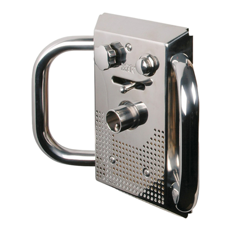
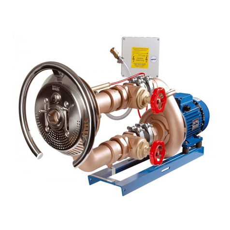
Anschlusssatz
Bestehend aus Anschlussarmatur aus Mineralwerkstoff und Blende aus Edelstahl A4, Sensorschalter mit 5 m Kabel
sowie Luftregulierung und Mengenverstellung. Die Einstrahldüse ist richtungsverstellbar.
Die Armatur hat einen stufenlosen Putzausgleich bis 35 mm. Pumpe aus Bronze, Sensorschaltung Schutzart IP65 und
Ansaugsieb ø350 mm aus Edelstahl A4.
Bei DIN-konformer Ausführung sind zwei Ansaugsiebe ø350 mm aus Edelstahl A4 im Lieferumfang.
Fittings
The fitting consists of the armature made of mineral material and a cover made of stainless steel 316L, sensor switch
with 5 m cable as well as a regulator for air and for quantities. The nozzle is adjustable in the direction. The armature
has a stepless adjustment on the surface up to 35 mm. Pump made of bronze, sensor control, protection class IP65
with 5 m cable and suction sieve 350 mm made of stainless steel 316L.
The type compliant to DIN includes two suction sieves Ø 350 mm made of stainless steel 316L.
Éléments de jonction
L´élément de jonction comprend partie avant en matière minérale et enjoliveur en INOX 316L, interrupteur
optique avec 5 m de câble ainsi qu´un bouton de réglage pour arrivée d´air. La tuyère de pulsion est orientable.
L´élément de jonction a de série la possibilité de ratrapage de niveau béton carrelage jusqu´a 35 mm. La pompe est
en bronze, le boîtier de commande pour l´interrupteur optique est également IP 65, une crépine de 350 mm en INOX
316L fait partie de l´ensemble.
Conforme norme DIN avec deux crépines de 350 mm en INOX 316L fait partie de l´ensemble.
3
a brand of Hugo Lahme GmbH
Art. Nr.: 577701
Stand 08/2010
In some very rare cases it is possible that during the operation of the counter-current an apparent stall
may occur due to the geometry of the pool. In such cases the assumption is suggested that the
installation does only work with lower capacity but the effective output of the pump is still assured
without any restrictions.
This phenomenon does not present any kind of defect on the pool installation. In fact, it is the result
of casual interactions of inflow and counterflow which are occurring unavoidably while operation and
use of the pool. Until now, such a phenomenon has only been noticed in connection with staircase
installations.
Dans certains très rares cas il est possible en fonction de la géométrie du bassin que la nage à
contre-courant montre une rupture de flux (tourbillon). Malgré que la puissance de jet sortie tuyère soit
conforme.
Ce phénomène ne conteste pas la conformité de l’installation du bassin. Mais est seulement à être traité
comme un hasard produit par des couches de courant (thermique de l´eau) allant dans différente direc-
tion dans le volume du bassin. Cet effet bizarre ne fut, jusqu´à maintenant seulement observé que dans
des bassins munis d´escaliers.
IMPORTANT ADVICE
INFORMATION IMPORTANTE
In einigen sehr seltenen Fällen kann es durch die Geometrie des Schwimmbeckens beim Betrieb
der Gegenschwimmanlage zu einem scheinbaren Strömungsabriss kommen. In diesem Fall liegt die
Vermutung nahe, dass die Anlage nur mit verminderter Leistung arbeitet, während die tatsächliche
Förderleistung jedoch uneingeschränkt gewährleistet ist.
Dieses Phänomen stellt keinen Mangel an der Schwimmbadanlage dar sondern ist begründet durch
zufällige Überlagerungen von An- und Gegenströmen, die sich im laufenden Betrieb und während der
Nutzung zwangsläufig in einem Schwimmbecken ergeben können. Bisher konnte eine derartige
Erscheinung allerdings auch nur in Verbindung mit Treppenanlagen beobachtet werden.
WICHTIGER HINWEIS

4
a brand of Hugo Lahme GmbH
Pumpenschacht
Pump shaft
Caisson de pompe
ACHTUNG:
Pumpe ist nicht für den Betrieb im Wasser geeignet!
Zwingend ist die Einbauanleitung Art. Nr.: 577086 der Pumpen zu beachten!
Es ist unbedingt eine Be- und Entlüftung sowie eine Entwässerung vorzusehen.
ATTENTION:
The pump is not suitable for operation in the water!
The manual of the pumps art. no. 577086 has to be completey observed.
Providing ventilation as well as a drainage in the pump shaft is absolutely necessary.
ATTENTION:
La pompe n´est pas appropriée pour une mise en marche immergée.
Il est indispensable de suivre impérativement les instructions concernent la pompe réf.: 577086
Il faut absolument prévoir une ventilation et aération ainsi qu`un drainage dans le caisson de pompe.
Mindestmaße / Minimum / Minimum: L = 150 cm, B = 50 cm
Höhe unter dem Wasserspiegel / Height below water level / Hauteur au dessous du niveau d`eau: 75 cm
Einbauhinweise
Installation Instructions
Mise en place de la pièce à sceller
ACHTUNG:
Sämtliche Metalleinbauteile sind gemäß VDE 0100 Teil 702 an einen Potentialausgleich
(Potentialringleitung) anzuklemmen.
Das Rückschlagventil muss über dem Wasserspiegel liegen!
Bei Schwimmbadabdeckungen müssen Abweiser an den Gegenschwimmanlagen montiert sein, weil
sonst der Sensorschalter durch Gegenschlagen der Schwimmbadabdeckung ausgelöst wird.
Die Verrohrung in DN65 wird bauseits erstellt.
ATTENTION:
All metal mounting parts have to be crossbonded and earthed (closed potential circuit) according to
German VDE 0100 part 702. The non-return-valve must be installed above the water level.
In case of pool covers deflectors have to be installed on the counter currents because otherwise the
sensor switch may be activated when knocking on the pool cover.
The piping in DN65 is made on site.
ATTENTION:
Toutes les pièces à sceller sont à relier au circuit équipotentiel. (Circuit équipotentiel en boucle)
Le clapet anti-retour doit être installé au dessus du niveau d`eau.
Dans le cas d´un bassin avec couverture faire attention que l´interrupteur optique n´ai pas de contact
avec la couverture afin d´éviter une mise en mache involontaire.
La tuyauterie DN65 est à faire en dehors du bassin.
Stand 08/2010 Art. Nr.: 577701

5
a brand of Hugo Lahme GmbH
Anschlussarmaturen
Connecting fittings
Élément de jonctions
ACHTUNG / ATTENTION / ATTENTION:
Die Bedienelemente sind in regelmäßigen Abständen einer Funktionsüberprüfung zu unterziehen!
The operation elements have to be controlled regarding their function regularly.
Le bon fonctionnement des boutons de réglages doit être contrôlés régulièrement.
CYCLON DUO
CYCLON
Art. Nr.: 577701
Stand 08/2010

6
a brand of Hugo Lahme GmbH
Anschlusssatz Cyclon DIN-konform, aus Bronze Art. Nr.: 8310021.
Fittings Cyclon compliant to DIN, made of bronze code 8310021.
Ensemble de raccordement conforme norme DIN, en bronze réf. 8310021.
Art. Nr.: / code / réf. 8310021
Pos. / item Stk. / quan. Art. Nr.: / code / réf. Artikelbezeichnung / product type / type de produit
Anschlussarmatur / connecting fitting / élément de jonction / Art. Nr.: / code / réf. 8320021
1. 1 8320021 Anschlussarmatur /connecting fitting / élément de jonction
2. 1 575522 Schlauchtülle / hose nozzle / embout de tuyau NW19/G1½
3. 2 500508 Schlauchschelle / hose clip / collier
4. 1 510580 Schlauch NW 19 / hose Ø19 / tuyau Ø19 500 mm
5. 1 8675050 Rückschlagventil / return valve / clapet anti-retour
6. 2 9165820 Ansaugsieb / suction sieve / crépine Ø350
Anschlusselemente / fitting kit / kit de raccordement / Art. Nr.: / code / réf. 8310551
7. 2 7006651 Verbindungselement / connection element / élément
de raccordement G2½/DN65
8. 2 562304 PVC-Kugelhahn / valve PVC / vanne à boule Ø75/DN65
9. 2 7182150191 Schlauchtülle / hose nozzle / embout de tuyau NW65/DN65
10. 4 575678 Schlauchschelle / hose clip / collier
11. 1 510501 Schlauch NW 65 / hose Ø65 / tuyau Ø65 200 mm
12. 1 510501 Schlauch NW 65 / hose Ø65 / tuyau Ø65 100 mm
13. 2 7162051 Schlauchtülle / hose nozzle / embout de tuyau NW65/IG G2½
14. 1 7158551 Pumpendruckstutzen / pump pressure socket /
embout de sortie de pompes G2½/90°
15. 1 7754051 Pumpe, DS / pump, 3 phase / pompe, tri 2,6 kW
16. 1 7336550 Schaltung / control / boîtier de commande
17. 1 7006651 Verbindungselement / connection element / élément
de raccordement G2½/DN65
Stand 08/2010 Art. Nr.: 577701

7
a brand of Hugo Lahme GmbH
Zusatzteile gehören nicht zum Lieferumfang und sind gesondert anzufordern!
Flanschsatz mit Dichtungen und Schrauben Art. Nr.: 8330151 für Anschlussarmatur.
Accessories are not part of the standard unit and have to be ordered seperately!
Flange kit with seals and screws code 8330151 for fitting.
Les accessoires ne faisant par partie du kit ceux-ci sont à commander séparément!
Flasque avec joint et vis de fixation réf. 8330151 pour élément de jonction.
Einbaubeispiel
Installation example
Exemple de montage
X = Mindestmaß vom fertigen Beckengrund
X = Minimum height finished pool bottom
X = Hauteur minimum fond de bassin
ACHTUNG:
Die Vorgaben der DIN EN 13451 sind bei der Installation zu berücksichtigen.
Um eine DIN - konforme Ansaugung zu gewährleisten, muss auf eine gleiche Länge der Verrohrung,
von den Ansauggehäusen zum Kugelhahn geachtet werden!
ATTENTION:
During the installation the instructions of DIN EN 13451 have to be considered.
For assuring that the suction complies with DIN, the equal length of the cabling from the suction housing
until the valves has to be used!
ATTENTION:
Les instructions de la norme DIN EN 13451 sont impérativement à respecter.
Pour assurer une aspiration conforme norme DIN, la tuyauterie doit impérativement être de même
longueur du boîtier d'aspiration jusqu'à la vanne à boule!
Wasserspiegel / Water level / Niveau d`eau
Art. Nr.: 577701
Stand 08/2010

8
a brand of Hugo Lahme GmbH
Stand 08/2010 Art. Nr.: 577701
Anschlusssatz Cyclon aus Bronze Art. Nr.: 8310121.
Fittings Cyclon made of bronze code 8310121.
Ensemble de raccordement en bronze réf. 8310121.
Art. Nr.: / code / réf. 8310121
Pos. / item Stk. / quan. Art. Nr.: / code / réf. Artikelbezeichnung / product type / type de produit
Anschlussarmatur / connecting fitting / élément de jonction / Art. Nr.: / code / réf. 8320021
1. 1 8320021 Anschlussarmatur /connecting fitting / élément de jonction
2. 1 575522 Schlauchtülle / hose nozzle / embout de tuyau NW19/G1½
3. 2 500508 Schlauchschelle / hose clip / collier
4. 1 510580 Schlauch NW 19 / hose Ø19 / tuyau Ø19 500 mm
5. 1 8675050 Rückschlagventil / return valve / clapet anti-retour
6. 1 9165820 Ansaugsieb / suction sieve / crépine Ø350
Anschlusselemente / fitting kit / kit de raccordement / Art. Nr.: / code / réf. 8310551
7. 2 7006651 Verbindungselement / connection element / élément
de raccordement G2½/DN65
8. 2 562304 PVC-Kugelhahn / valve PVC / vanne à boule Ø75/DN65
9. 2 7182150191 Schlauchtülle / hose nozzle / embout de tuyau NW65/DN65
10. 4 575678 Schlauchschelle / hose clip / collier
11. 1 510501 Schlauch NW65 / hose Ø65 / tuyau Ø65 200 mm
12. 1 510501 Schlauch NW65 / hose Ø65 / tuyau Ø65 100 mm
13. 2 7162051 Schlauchtülle / hose nozzle / embout de tuyau NW65/IG G2½
14. 1 7158551 Pumpendruckstutzen / pump pressure socket /
embout de sortie de pompes G2½/90°
15. 1 7754051 Pumpe, DS / pump, 3 phase / pompe, tri 2,6 kW
16. 1 7336550 Schaltung / control / boîtier de commande

9
a brand of Hugo Lahme GmbH
Stand 08/2010 Art. Nr.: 577701
Zusatzteile gehören nicht zum Lieferumfang und sind gesondert anzufordern!
Flanschsatz mit Dichtungen und Schrauben Art. Nr.: 8330051 für Anschlussarmatur.
Accessories are not part of the standard unit and have to be ordered seperately!
Flange kit with seals and screws code 8330051 for fitting.
Les accessoires ne faisant par partie du kit ceux-ci sont à commander séparément!
Flasque avec joint et vis de fixation réf. 8330051 pour élément de jonction.
Einbaubeispiel
Installation example
Exemple de montage
Wasserspiegel / Water level / Niveau d`eau
X = Mindestmaß vom fertigen Beckengrund
X = Minimum height finished pool bottom
X = Hauteur minimum fond de bassin

10
a brand of Hugo Lahme GmbH
Stand 08/2010 Art. Nr.: 577701
Anschlusssatz Cyclon Duo DIN-konform, aus Bronze Art. Nr.: 8310221.
Fittings Cyclon Duo compliant to DIN, made of bronze code 8310221.
Ensemble de raccordement conforme norme DIN, en bronze réf. 8310221.
Art. Nr.: / code / réf. 8310221
Pos. / item Stk. / quan. Art. Nr.: / code / réf. Artikelbezeichnung / product type / type de produit
Anschlussarmatur / connecting fitting / élément de jonction / Art. Nr.: / code / réf. 8320121
1. 1 8320121 Anschlussarmatur /connecting fitting / élément de jonction
2. 1 575522 Schlauchtülle / hose nozzle / embout de tuyau NW19/G1½
3. 2 500508 Schlauchschelle / hose clip / collier
4. 1 510580 Schlauch NW 19 / hose Ø19 / tuyau Ø19 500 mm
5. 1 8675050 Rückschlagventil / return valve / clapet anti-retour
6. 2 9165820 Ansaugsieb / suction sieve / crépine Ø350
Anschlusselemente / fitting kit / kit de raccordement / Art. Nr.: / code / réf. 8310551
7. 2 7006651 Verbindungselement / connection element / élément
de raccordement G2½/DN65
8. 2 562304 PVC-Kugelhahn / valve PVC / vanne à boule Ø75/DN65
9. 2 7182150191 Schlauchtülle / hose nozzle / embout de tuyau NW65/DN65
10. 4 575678 Schlauchschelle / hose clip / collier
11. 1 510501 Schlauch NW 65 / hose Ø65 / tuyau Ø65 200 mm
12. 1 510501 Schlauch NW 65 / hose Ø65 / tuyau Ø65 100 mm
13. 2 7162051 Schlauchtülle / hose nozzle / embout de tuyau NW65/IG G2½
14. 1 7158551 Pumpendruckstutzen / pump pressure socket /
embout de sortie de pompes G2½/90°
15. 1 7754051 Pumpe, DS / pump, 3 phase / pompe, tri 2,6 kW
16. 1 7336550 Schaltung / control / boîtier de commande
17. 1 7006651 Verbindungselement / connection element / élément
de raccordement G2½/DN65

11
a brand of Hugo Lahme GmbH
Stand 08/2010 Art. Nr.: 577701
Zusatzteile gehören nicht zum Lieferumfang und sind gesondert anzufordern!
Flanschsatz mit Dichtungen und Schrauben Art. Nr.: 8330151 für Anschlussarmatur.
Accessories are not part of the standard unit and have to be ordered seperately!
Flange kit with seals and screws code 8330151 for fitting.
Les accessoires ne faisant par partie du kit ceux-ci sont à commander séparément!
Flasque avec joint et vis de fixation réf. 8330151 pour élément de jonction.
Einbaubeispiel
Installation example
Exemple de montage
Wasserspiegel / Water level / Niveau d`eau
ACHTUNG:
Die Vorgaben der DIN EN 13451 sind bei der Installation zu berücksichtigen.
Um eine DIN - konforme Ansaugung zu gewährleisten, muss auf eine gleiche Länge der Verrohrung,
von den Ansauggehäusen zum Kugelhahn geachtet werden!
ATTENTION:
During the installation the instructions of DIN EN 13451 have to be considered.
For assuring that the suction complies with DIN, the equal length of the cabling from the suction housings
until the valves has to be used!
ATTENTION:
Les instructions de la norme DIN EN 13451 sont impérativement à respecter.
Pour assurer une aspiration conforme norme DIN, la tuyauterie doit impérativement être de même
longueur du boîtier d'aspiration jusqu'à la vanne à boule!
X = Mindestmaß vom fertigen Beckengrund
X = Minimum height finished pool bottom
X = Hauteur minimum fond de bassin

12
a brand of Hugo Lahme GmbH
Anschlusssatz Cyclon Duo aus Bronze Art. Nr.: 8310321.
Fittings Cyclon Duo made of bronze code 8310321.
Ensemble de raccordement en bronze réf. 8310321.
Art. Nr.: / code / réf. 8310321
Pos. / item Stk. / quan. Art. Nr.: / code / réf. Artikelbezeichnung / product type / type de produit
Anschlussarmatur / connecting fitting / élément de jonction / Art. Nr.: / code / réf. 8320121
1. 1 8320121 Anschlussarmatur /connecting fitting / élément de jonction
2. 1 575522 Schlauchtülle / hose nozzle / embout de tuyau NW19/G1½
3. 2 500508 Schlauchschelle / hose clip / collier
4. 1 510580 Schlauch NW 19 / hose Ø19 / tuyau Ø19 500 mm
5. 1 8675050 Rückschlagventil / return valve / clapet anti-retour
6. 1 9165820 Ansaugsieb / suction sieve / crépine Ø350
Anschlusselemente / fitting kit / kit de raccordement / Art. Nr.: / code / réf. 8310551
7. 2 7006651 Verbindungselement / connection element / élément
de raccordement G2½/DN65
8. 2 562304 PVC-Kugelhahn / valve PVC / vanne à boule Ø75/DN65
9. 2 7182150191 Schlauchtülle / hose nozzle / embout de tuyau NW65/DN65
10. 4 575678 Schlauchschelle / hose clip / collier
11. 1 510501 Schlauch NW65 / hose Ø65 / tuyau Ø65 200 mm
12. 1 510501 Schlauch NW65 / hose Ø65 / tuyau Ø65 100 mm
13. 2 7162051 Schlauchtülle / hose nozzle / embout de tuyau NW65/IG G2½
14. 1 7158551 Pumpendruckstutzen / pump pressure socket /
embout de sortie de pompes G2½/90°
15. 1 7754051 Pumpe, DS / pump, 3 phase / pompe, tri 2,6 kW
16. 1 7336550 Schaltung / control / boîtier de commande
Stand 08/2010 Art. Nr.: 577701

13
a brand of Hugo Lahme GmbH
Zusatzteile gehören nicht zum Lieferumfang und sind gesondert anzufordern!
Flanschsatz mit Dichtungen und Schrauben Art. Nr.: 8330051 für Anschlussarmatur.
Accessories are not part of the standard unit and have to be ordered seperately!
Flange kit with seals and screws code 8330051 for fitting.
Les accessoires ne faisant par partie du kit ceux-ci sont à commander séparément!
Flasque avec joint et vis de fixation réf. 8330051 pour élément de jonction.
Einbaubeispiel
Installation example
Exemple de montage
X = Mindestmaß vom fertigen Beckengrund
X = Minimum height finished pool bottom
X = Hauteur minimum fond de bassin
Wasserspiegel / Water level Niveau d`eau
Art. Nr.: 577701
Stand 08/2010

14
a brand of Hugo Lahme GmbH
Schaltung
Wiring
Commande electro
Elektrischer Anschluss (bauseits zu erstellen)
Für die Schaltung wird ein Zuleitungskabel von 5 x 2,5 mm² benötigt. Absicherung 3x16 Ampere träge.
Fehlerstromschutzschalter (FI-Schalter / Nennfehlerstrom 30 mA), der für die Gegenschwimmanlage bestimmt ist muss in jedem Fall
installiert werden. Das Zuleitungskabel von der Schaltung zur Drehstrom-Pumpe ist 4 x 2,5 mm².
Einbau der Schaltung
Die maximale Entfernung der Schaltung vom Sensortaster beträgt 25 m.
Die Schaltung ist in einem trockenen Raum zu installieren.
Zur Sicherung der Pumpe ist ein Motorschutzrelais in die Schaltung eingebaut. Dieses Motorschutzrelais muss bauseitig eingestellt
werden. Die Stromaufnahme der einzelnen Phasen ist im Betriebszustand zu messen.
Das Motorschutzrelais ist auf den Nennstrom des Motors einzustellen. Eine Funktionsprüfung ist unbedingt erforderlich.
ACHTUNG: Die Vorschriften des VDE und des örtlichen EVU (Elektrizitäts-Versorgungs-Unternehmen) sind bei
der Installation der Anlage unbedingt zu beachten. Installation nur durch einen beim örtlichen EVU
zugelassenen Elektro-Installateur, nach VDE 0100 Teil 702 und 430 ausführen lassen.
Electrical connection (to be made on site)
You need a power supply cable. 5 x 2.5 mm² for the control box. Delay fuse 3x16 ampere.
The Residual Current Device (RCD FI-stream protection 30mA) which is designated for the counter-current has always to be installed.
The power supply cable of the control to the three-phase current pump is 4 x 2.5 mm².
Installation of the control
The maximum distance from the control to the sensor switch is 25 m.
The control has to be installed in a dry place.
A relay for motor protection is built in the control for the protection of the pump. This relay for motor protection has to be adjusted
on site. The power input of the seperate phases has to be measured during the operation process. The relay for motor protection has
to be adjusted to the measured rated current of the motor. A control of this function is absolutly necessary.
ATTENTION: During the installation you have to follow the installation regulations and regulations of the responsible
Energy Supply Company. The installation work has to be conducted only by a certified electrician
according to German standard VDE 0100 part 702 and 430.
Raccordement électrique (hors construction)
Le raccordement de la pompe doit être effectué à l´aide d´un câble 5x 2,5 mm² d´une protection primaire avec un fusible de
3x16 A/T et d´un disjoncteur FI (différentiel de perte 0,30 mA), est nécessaire pour la nage à contre courant, cette protection
supplémentaire suivant la norme C 1500 /VDE 010013 N. doit être installée.
Le câble d´alimentation de la commande à la pompe est 4 x2,5 mm².
Mise en place d´un interrupteur optique:
La distance maximum de la commande au boîtier de commande est de 25 m .
La commande est à installer dans un local sec.
Le relais thermique pour la protection de pompe se trouve dans la commande.
L´installateur électricien doit calibrer le relais thermique en fonction d´une mesure de courant nominal (pince ampèrmetrique)
nécessaire sur les phases. Un contrôle de fonction est absolumment necessaire.
ATTENTION: Les réglementations VDE et des distributeurs d´énergie régionaux, sont obligatoirement à respecter.
L´installation ne doit être réalisée que par un électricien agrée par ces organismes, et avoir les connaissances des
différentes normes VDE 0100 § 702 et 430 et de la C 1500 -702.
Stand 08/2010 Art. Nr.: 577701

15
a brand of Hugo Lahme GmbH
Schaltbild Schaltung Art. Nr.: 7336550
Circuit diagram code 7336550
Schéma de raccordement réf. 7336550
ACHTUNG:
Die Schaltleistung der Steuerplatine vom Sensorschalter beträgt max. 1 Ampere!
Motorschutzrelais einstellen!
ATTENTION:
The power of the control panel of the sensor switch is 1 ampere maximum!
Adjust the relay for motor protection!
ATTENTION:
La puissance maximum d'interruption du relais interne de la platine est 1 ampère!
Calibrer le relais thermique!
ACHTUNG:
Sensorschalter nicht öffnen,
da sonst Gewährleistungsverlust!
ATTENTION:
Do not open the sensor switch,
otherwise lost of guarantee!
ATTENTION:
Ne jaimais ouvrir l`interrupteur
optique, sous perte de garantie
constructeur!
Art. Nr.: 577701
Stand 08/2010

16
a brand of Hugo Lahme GmbH
Stand 08/2010 Art. Nr.: 577701
1. Standort
Es wird empfohlen, das Pumpenaggregat der Gegenschwimmanlage so anzuordnen, dass die Verbindung zwischen
Pumpe und Armaturenteilen so kurz wie möglich gehalten wird. Es ist auf jeden Fall darauf zu achten, dass der
Einbau des Pumpenaggregates so vorgenommen wird, dass die Achse waagerecht verläuft. Es ist möglich, dass
der Standort der Pumpen aus baulichen Gründen verlegt wird. Damit nicht zu grosse Strömungsverluste in der
Saugleitung auftreten, empfehlen wir eine Entfernung von max. 5 m nicht zu überschreiten, wobei darauf zu achten
ist, dass bei diesem Maximalbereich die Rohre knickfrei und waagerecht verlegt werden. Bei grösseren Entfernungen
muss der Querschnitt der Rohrleitung entsprechend vergrössert werden. Der Standort der Pumpe ist so zu wählen,
dass eine Umgebungstemperatur von 40° Celcius nicht überschritten wird. Da das Pumpenaggregat serienmässig
nicht selbstansaugend ist, ist es unterhalb der Wasserspiegellinie zu installieren. Die Pumpe und Absperrelemente
müssen jederzeit leicht zugänglich sein. Eine Be- und Entlüftung sowie Bodenablauf sind unbedingt im Pumpenschacht
ausreichend dimensioniert vorzusehen.
2. INSTALLATION
Die Anlage wird serienmäßig mit allen erforderlichen Anschlusselementen geliefert. Der Einbausatz ist passend für
eine 240 mm / 250 mm starke Betonwand ausgelegt. Er sollte so eingebaut werden, dass die Mitte der Strahldüse
ca. 200 - 250 mm unter dem Wasserspiegel liegt und einen Mindestabstand zur seitlichen Wand von 1,5 m hat.
Nach Fertigstellung der Bauarbeiten und Säubern der Einbausätze wird die Armatur montiert. Luft- und Sensoranschluss
sind mit den entsprechenden Übergängen im Einbausatz zu verbinden. Beim Einschieben der Armatur dürfen die
Schläuche / Kabel nicht geknickt werden. Die Armatur mittels der mitgelieferten Schrauben am Einbausatz befestigen.
Im Pumpenschacht wird anschliessend an dem Luftschlauch das Rückschlagventil angebracht. Das Rückschlagventil
muss über dem Wasserspiegel befestigt werden. Das Sensorkabel an der Schaltung anschliessen. Das Ansaugsieb
mittels der mitgelieferten Schrauben am Einbausatz befestigen. Die Verbindung zwischen Pumpe und Einbausatz wird
nach Zeichnung und Stückliste hergestellt. Die Verrohrung wird bauseits erstellt.
3. INBETRIEBNAHME
Anlage nur bei gefülltem Becken in Betrieb nehmen. Ein Trockenlauf der Pumpe ist unbedingt zu vermeiden.
1. Beide Kugelhähne öffnen und Anlage über den Sensorschalter einschalten,
2. Luftbeimischung prüfen
3. Mengenverstellung überprüfen
4. Schlauch- oder Rohrverbindungen im Betriebszustand auf Leckage prüfen. Durch Temperaturunterschiede kann
ein Nachziehen der Verbindungen erforderlich werden. (Armatur soweit wie möglich drosseln und auf Leckage prüfen).
4. BEDIENUNG
Über den Sensorschalter wird die Anlage durch Fingerdruck ein- und ausgeschaltet. Der Luftregler ermöglicht ein
Beimischen von Luft in den Wasserstrahl . Durch Einstellen der Mengenverstellung kann die Wasserstrahlstärke
eingestellt werden. Die Einstrahldüsen sind richtungsverstellbar. Der Wasserstrahl sollte so verändert werden,
dass der Schwimmer gegen den vollen Strahl schwimmt.
5. ÜBERWINTERN
Die Pumpe muss unbedingt entleert werden. Beide Kugelhähne zudrehen und Entleerungsschraube am
Pumpengehäuse öffnen.
6. Störungssuche
6-1. Anlage bringt nicht genug Leistung: Falsche Drehrichtung der Pumpe. Wasserspiegel nicht hoch genug.
Pumpe saugt Luft. Kugelhahn nicht ganz offen. Saugleitung undicht. Pumpe verstopft (Blätter etc.).
Sollten keine erkennbaren Ursachen vorliegen, muss der Kundendienst benachrichtigt werden.
6-2. Pumpe kann nicht eingeschaltet werden: Kabel zwischen Sensortaster und Schaltung, sowie Anschlußbelegung der
Schaltung überprüfen.
6-3. Motorschutzrelais schaltet ab: Falsche Einstellung des Motorschutzrelais. Motornennstrom und örtliche Verhältnisse müssen
mit der Einstellung des Motorschutzrelais übereinstimmen. Pumpe überhitzt - Motor abkühlen lassen und erneuz einschalten.
Phase ausgefallen - Sicherung überprüfen.
6-4. Fehlerstromschutzschalter schaltet ab: Anlage muss unbedingt von einem Elektroinstallateur überprüft werden.
Einbau- und Bedienungsanleitung

17
a brand of Hugo Lahme GmbH
Art. Nr.: 577701
Stand 08/2010
1. POSITION
It is recommended to place the pump of the counter-current in a way that the connection between the pump and the
fitting parts is as short as possible. In any case you have to ensure that the pump is installed in a manner that the
axle is in a horizontal position. Changing the place of the pump is possible due to construction reasons.
We recommend not to go beyond 5 m maximum distance for avoiding any higher flow reduction on the suction side.
While placing the installation please ensure that the pipes in that maximum area are passed without breakes and
in a horizontal way. If there are larger distances, you have to increase the diametre of the pipes. The place of
the pump has to be an area, where the ambient temperature does not exeed 40°C. Place the pump under the
water level because the pump does not suck itself. The pump and the locking parts have to be accessible any time.
Ventilation and drainage as well as floor drain have to be provided in the pump shaft.
2. INSTALLATION
The equipment is supplied as standard with all nessary fittings. The wall pack is suitable for 240 / 250 mm
concrete wall. The wall pack should be mounted in a way that the centre of the nozzle is between
200 and 250 mm below water level and is not placed less than 1,5 m from the side wall.
After finishing of the construction and cleaning of the fitting parts, you may assemble the unit.
The air and sensor connection of the fitting have to be connected with the transitions in the wall pack.
When pushing the fitting in, the hoses may not get broken. Fix the fitting by using the delivered screws
on the wall pack. Now, the non-return-valve in the pump shaft has to be connected to the air hose.
The non-return-valve has to be installed above water level. The sensor cable has to be connected to
the control box. Fix the suction sieve with the delivered screws on the wall pack. The connection between
the pump and the wall kit is made according to the drawing and part list. The piping is made on site.
3. STARTING UP
Ensure that the pool is full of water before starting up the pump. Avoid any dry run of the pump.
1. Open both valves and turn on the installation by using the sensor switch.
2. Check the air injection.
3. Check the regulation of the quantity.
4. Hose and tube connections have to be checked on leakage during the working process. Due to temperature
differences tighting of the connections can get neccessary. (Check the system on leakage by reducing the installation
as much as possible).
4. OPERATING
It is switched on and off by using the sensor switch. The air regulator enables to mix the air into the water jet. The intensity of the
water jet is adjusted by the quantity regulation. The nozzle can be adjusted in the direction. Adjust the current speed in a way that
the swimmer can swim against the full jet.
5. HIBERNATION
The pump has to be empty. Close both valves and open the screw on the housing of the pump for emptying.
6. POSSIBLE PROBLEMS AND SOLUTIONS
6-1. Installation does not produce sufficient power: Pump is turning in the wrong direction. Water level is too low.
Pump sucks in air. Valve is not completly open. Suction pipe leaks. Pump is clogged (with leaves for instance).
If the causes can not be identified, inform the service responsible.
6-2. Pump can not be switched on: Check the cable between the sensor switch and the control and check the configuration
of the connection of the control.
6-3. Relay for motor protection switches off: Relay for motor protection is not adjusted correctly. Rated current and local situations
have to be consistent with the adjustment of the relay for motor protection. Pump is overheated. Cool down the motor and
start it again. Phase failed - check the fuses.
6-4. Residual Current Device (RCD) switches off: The equipment has to be checked by an electrician.
Installation instructions

18
a brand of Hugo Lahme GmbH
1. EMPLACEMENT
Il est conseillé de placer le groupe électro-pompe de nage à contre courant de façon à ce que le raccordement entre
la pompe et les pièces à sceller et boîtier de commande soit aussi réduit que possible. Veiller à ce que l´axe du
groupe électro-pompe soit horizontal. Celui ci peut être déplacé mais, afin d´éviter des pertes de charge importantes
dans le conduit d´aspiration. Il est conseillé de ne pas dépasser une distance de 5 m. D´autre part, il est important
que la tuyauterie à distance maximale que celle-ci soit posée horizontalement et sans coudes éventuellement
pour grande distance la section de tuyauterie doit être à cette effet dimensionnée. Il est indispensable de placer
la pompe dans un endroit où la température ambiante ne dépasse pas 40° C. Le groupe électro-pompe, n´étant pas
auto-amorçant, doit être installé en-dessous du niveau de l´eau. La pompe et les vannes d´arrêt doivent être
facilement accessibles. Dans le puits de pompe (ou local technique enterré), il est absolument indispensable de
prévoir un système de ventilation et un drainage (écoulement).
2. INSTALLATION
La livraison comprend de série toutes les pièces à sceller ainsi que les éléments de raccordement. Les pièces à
sceller sont prévues pour un coffrage de 240mm/250mm. Les pièces à sceller doivent être positionnées de manière
telle que le milieu de celle-ci se trouve à environ 200 - 250 mm au-dessous du niveau d´eau. La distance entre un mur
latéral ne doit pas être inférieure à 1,50 m. Après décoffrage et autre gros œuvre un nettoyage des pièces à sceller est
indispensable. Éffectuer le montage de l´élément de raccordement. Le tuyau pour l´air et le câble pour bouton optique
sont à introduire dans le presse étoupe prévue à cet effet dans la pièce à sceller. Le positionnement de la face avant
doit être réalisé tel que le tuyau ou câble ne soit pas fortement plié. Fixer la face avant de la nage à contre-courant
sur la pièce murale à l´aide des vis faisant partie de la livraison. Dans le local technique le clapet anti-retour est à fixer
sur la conduite d´appel d´air le positionnement de celui-ci doit être impérativement au-dessus du niveau d´eau.
Le tuyau ou câble doivent être raccordé au boîtier de commande. Le raccordement entre la pompe et la pièce
à sceller de NCC et à faire suivant le schéma de montage et la liste de pièces et accessoires.
3. MISE EN SERVICE
Ne mettre en service l´installation que lorsque le bassin est plein d´eau. Une mise en marche de la pompe à sec
est absolument à éviter.
1. Ouvrir les deux vannes et faire une mise en marche à l´aide de l´interrupteur optique.
2. Contrôler l´addition d´air.
3. Contrôler le réglage de débit.
4. Contrôler les raccords des tuyaux en état de marche, par différence de température. Il est possible qu´un serrage
des colliers soit nécessaire (réduire le débit pour contrôler l´étanchéité)
4. EMPLOI
La plaque côte bassin de la nage à contre courant comprend tous les éléments de commande. L`arrêt et la mise en
marche de l`appareil s`effectue par la pression d`un doigt, sur l`interrupteur optique. Le régulateur d`air rend possible une
addition d´air au jet d´eau. Par réglage du débit d`eau, la puissance du jet d`eau peut être modulé et la buse peut être orientée
dans toutes les directions. La direction du jet doit être directement sur le nageur.
5. HIVERNAGE
La pompe doit être vidangée. Fermer les deux vannes et ouvrir la vis de vidange sur le corps de pompe.
6. RECHERCHE DES PANNES
6-1. L´installation n´a pas le débit suffisant: Mauvais sens de rotation de la pompe. Le niveau d´eau de bassin
n´est pas suffisant. Conduite d´aspiration non étanche. Les vannes ne sont pas ouvertes complètement.
La pompe est obstruée (feuilles, etc.). S’il n´y a pas d´autre causes, contacter notre service après-vente.
6-2. La pompe ne peut pas être mise en marche: Le câble entre l´interrupteur optique et la commande et les
raccordements sont à contrôler.
6-3. Le relais thermique se déclenche: Mauvais réglage du relais thermique. La puissance du moteur doit
correspondre au réglage du relais thermique (plaque signalétique). Au cas d'échauffement de pompe, laisser refroidir
le moteur et réenclencher. Faute de phase, contrôler les fusibles.
6-4. Déclenchement du disjoncteur différentiel: L´installation doit être absolument contrôlée par un électricien.
Stand 08/2010 Art. Nr.: 577701
Mise en place et mode d`emploi

19
a brand of Hugo Lahme GmbH
Technische Daten
Der effektive Förderstrom ist abhängig von der Art der gewählten Verrohrung.
Pumpenleistung: 2,6 KW DS 230/400 Volt, 50 Hz Leistungsaufnahme: 3,4 KW
Stromaufnahme: 5,5 A
Durchflussmenge ca. 60 m³/h, bei einem Gegendruck von 1,1 bar.
Luftbeimischung zwischen 0,1 bis ca. 5%.
Durchflussmenge regelbar zwischen ca. 60 m³/h und ca. 36 m³/h.
Technical specification
The effective flow rate depends on the configuration of the pipework.
Rating: 2,6 KW 3 phase 230/400 V, 50 Hz Power consumption: 3,4 KW
Current consumption 5,5 A
Flow rate approximately 60m³/h on 1.1 bar counter pressure.
Addition of air approximately 0,1 up to approximately 5 %.
Flow rate adjustable between approximately 60 m³/h and approx. 36m³/h.
Données techniques
Le débit effectif est dépendant de la distance de la pompe.
Puissance de la pompe: 2,6 KW tri-phasés 230/400 Volt, 50 Hz Puissance absorbée: 3,4 KW
Courant d´appel 5,5 A
Débit de la pompe environ 60 m³/h ave une contre-pression de 1,1 bar.
Le réglage d´apport d´air est de 0,1 à environ 5 %.
Le réglage d´apport d´air est réglable entre environ 60m³/h et environ 36m³/h.
Art. Nr.: 577701
Stand 08/2010
Kennlinie Pumpe / identity line pump / signalétique de pomp
Technische Änderungen vorbehalten Technical amendments reserved Modifivations techniques sous réserves
Kennlinie Rotgusspumpen Drehstrom
0
10
20
30
40
50
60
70
80
90
100
110
120
130
140
2,6 KW (DS)
20,50 20,28 19,56 18,31 16,50 14,28 11,47 6,66
11,50 11,50 11,50 11,50 11,50 11,50 11,50 11,50
Förderhöhe
in (m)
Fördermenge / delivery / debit (m³/h)
0,00
5,00
10,00
15,00
20,00
25,00
0 10 20 30 40 50 60 70
Fördermenge / delivery / Debit (m³/h)
Förderhöhe / delivery high / Hauteur Manomètrique (m)
Stand: 02.2007 Z:\3-D CAD\WG5\Einbauanltg\FitStar\577701 Gegenschwimmanlagen_Cyclon_und_Cyclon_Duo\Zeichnungen\Kennlinien Rotgusspumpe Drehstrom

20
a brand of Hugo Lahme GmbH
Perfektion in jedem Element
Kahlenbecker Straße 2 · 58256 Ennepetal · Germany
Telefon +49 (0) 23 33 / 96 96 0 · Telefax +49 (0) 23 33 / 96 96 46
E-Mail: [email protected] · Internet: www.lahme.de
HUGO LAHME
This manual suits for next models
1
Table of contents
Other Hugo Lahme Lighting Equipment manuals

Hugo Lahme
Hugo Lahme FitStar Double-Jet User manual

Hugo Lahme
Hugo Lahme FitStar Standard User manual

Hugo Lahme
Hugo Lahme Fit Star User manual

Hugo Lahme
Hugo Lahme AllFit 1252020 Specification sheet

Hugo Lahme
Hugo Lahme FitStar Standard User manual

Hugo Lahme
Hugo Lahme Fit Star User manual

Hugo Lahme
Hugo Lahme FitStar GSA-TAIFUN DUO User manual
Popular Lighting Equipment manuals by other brands

Show Tec
Show Tec Helios 200 COB Q4 manual

Astral Pool
Astral Pool 3.000 l/h Installation and maintenance manual

MegaLite
MegaLite PAN T BOT user manual

Claypaky
Claypaky AXCOR BEAM 300 instruction manual

HAMPTON BAY
HAMPTON BAY HB-4132-MB Use and care guide

Claypaky
Claypaky ALPHA SPOT QWO 800 instruction manual