Hugo Müller GmbH & CO KG ●Karlstraße 90 ●78054 VS-Schwenningen ●E-Mail: info@hugo-mueller.de ●www.hugo-mueller.de
BA GSxx00mod TSxx00mod Hardware HM; de, en -23876- 2023.01 V04 ED
BEDIENUNGSANLEITUNG LUFTGÜTESENSOREN GS 4X.00 MOD / GS 3X.00 MOD / TS 3X.00 MOD
SICHERHEIT UND GRUNDLAGEN
Technische Daten
Siche heitshinweise / Bestimmungsgemäße Ve wendung
Anschlussspannung:
Busstrom:
12-40 V DC
< 20 mA
WARNUNG! ES BESTEHT GEFAHR DURCH EINEN ELEKTRISCHEN SCHLAG ODER BRANDGEFAHR!
!!!Einbau, Anschluss und Montage dü fen ausschließlich von eine Elekt ofachk aft du chgefüh t we den!!!
Nur an di auf d m G rät ang g b n Spannung und Fr qu nz anschli ß n! [12-40 V DC]
B i Eingriff n od r Änd rung n am G rät rlischt di Garanti !
Das G rät ist so zu installi r n, dass auch auß rg wöhnlich hoh Störstrahlung di Funktion nicht b inträchtig n kann!
Installation und Anschluss dürf n nur ntspr ch nd d n national n Bau- und El ktrovorschrift n / Sich rh itsb stimmung n durchg führt w rd n!
B schädigt G rät dürf n nicht in B tri b bzw. müss n sofort auß r B tri b g nomm n w rd n!
B acht n Si di Vorschrift n und Hinw is aus d m Handbuch „Haus- und G bäud syst mt chnik“ d s ZVEI/ZVEH. Di s gilt insb sond r für di fachg r cht V rl gung
d r Busl itung n und di Inb tri bnahm d s KNX G rät s
Das G rät ist zur V rw ndung für folg nd Aufgab n vorg s h n: Üb rwachung d r Luftgüt in d r G bäud syst mt chnik (Schul , Büro, Hot l, Tagungsstätt tc.),
Dat nüb rtragung und R g lung p r Bus-Syst m.
Das G rät ist für d n B tri b g mäß d n aufg führt n t chnisch n Dat n g ign t.
Das G rät ist ausschli ßlich zum Einsatz in trock n n Räum n g ign t.
Das G rät ist nicht g ign t für sich rh itsr l vant Aufgab n, wi z.B. Fluchttür n, Brandschutz inrichtung n, Gärk ll r tc.
2
2
M ssb r ich r l. Luftf uchtigk it
Zulässig Umg bungst mp ratur
s lbstv rlösch nd s Th rmoplast
III b i b stimmungsg mäß r Montag
Di M ss rg bniss d s G rät s könn n durch
äuß rlich Einflüss n gativ b influsst w rd n.
Möglich Störqu ll n sind:
■ Zugluft und Luftb w gung:
z.B. durch F nst r, Tür n, Konv ktion, H izung
od r P rson n.
■ Erwärmung od r Abkühlung:
z.B. Sonn nb strahlung od r d r Montag an
in r Auß nwand.
■ Wärm qu ll n: In dir kt r Näh zu
l ktrisch n V rbrauch rn, z.B. Dimm r
Erschütt rung n od r Schläg , d n n das
G rät ausg s tzt wird od r wurd .
■ V rschmutzung durch Farb , Tap t nkl ist r,
Staub, tc.: z.B. b i R novi rungsarb it n
■ Organisch Lös mitt l od r d r n Dämpf :
z.B. R inigungsmitt l.
■ W ichmach r aus Aufkl b rn und
V rpackung n:
z.B. Luftpolst rfoli od r Styropor
Das G rät ist nicht für ig nmächtig baulich
V ränd rung n, R paratur n und sich rh itsr l vant
Aufgab n vorg s h n.
Das G rät ist nicht für d n Einsatz im Auß nb r ich und
in Nassz ll n vorg s h n.
Das G rät ist nicht für sich rh itsr l vant Aufgab n
g ign t. Di St u rung d s G rät s di nt all in zur
Üb rwachung und R g lung d r Luftqualität.
Di b stimmungswidrig V rw ndung d s G rät s kann
zu Sach- und P rson nschäd n führ n.
Das G rät ist umw ltg r cht und ntspr ch nd d n
El ktrovorschrift n zu ntsorg n.
Steue ausgang Messwe tausgabe
T mp ratur 0 – 50 °C (0 – 10 Volt)
R lativ Luftf uchtigk it 0 – 100% RH (0 – 10 Volt)
Kohl nstoffdioxid CO
2
0 – 2000 ppm (0 – 10 Volt)
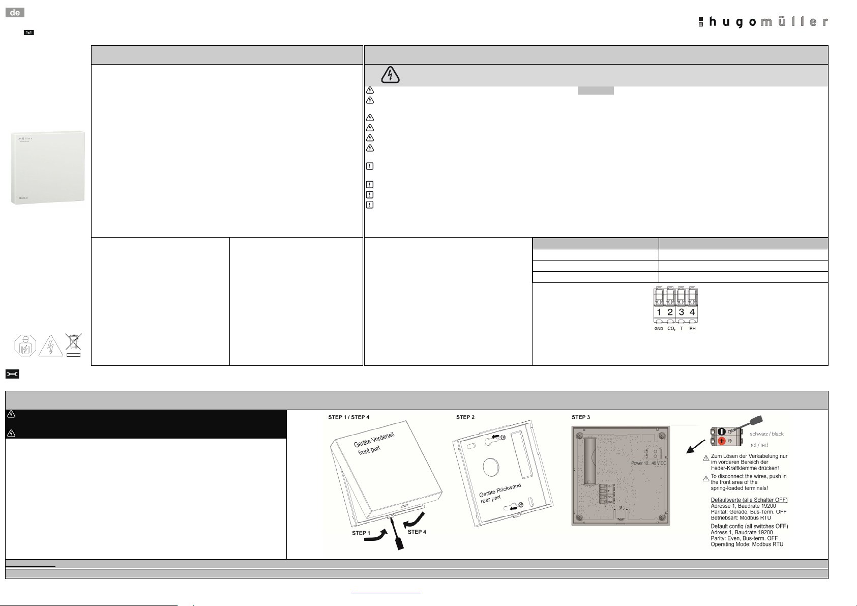
MONTAGE
Montage
Vo Montage- und Installationsa beiten Spannung f eischalten und Spannungsf eiheit
p üfen!
Beachten Sie unbedingt die weite en, oben aufgefüh ten Siche heitshinweise!
Das G rät ist für di Montag auf in r Unt rputzdos od r für di dir kt Wandmontag g ign t
Bitt acht n Si darauf, dass k in Staub in das G rät g langt
Nach Inb tri bnahm b nötigt das G rät ca. 5 Minut n bis zur rst n korr kt n M ssung.
Rückwand auf in r Unt rputzdos bzw. an d
monti r n
G rät mit d r RS485 Schnittst ll
notw ndig n Param t r konfiguri r n. Spannungsv rsorgung anschli ß n.
Abd ckung nach rfolgt m Anschluss darauf acht n, dass k in L itung n ing kl mmt od r g qu tscht w rd n. Di V rw ndung in
r Unt rputzdos wird für in infach r L itungsführung mpfohl n.


